The Flip Design Increases Potential Problems
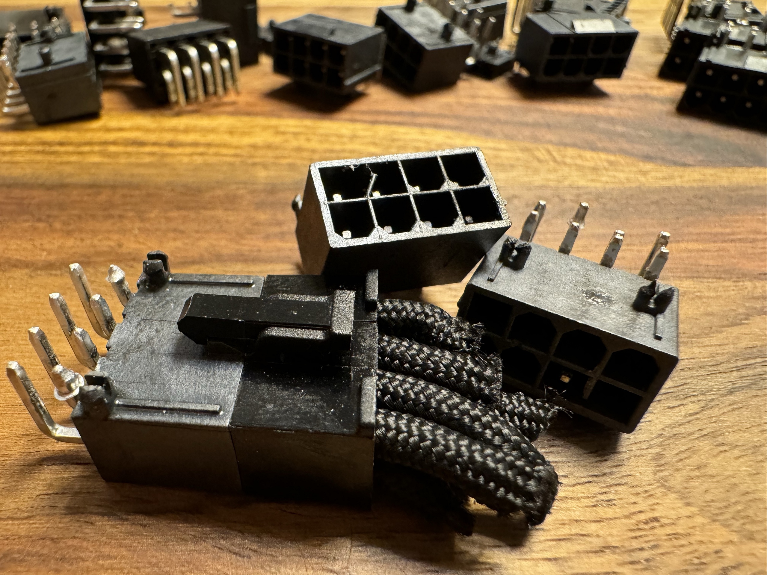
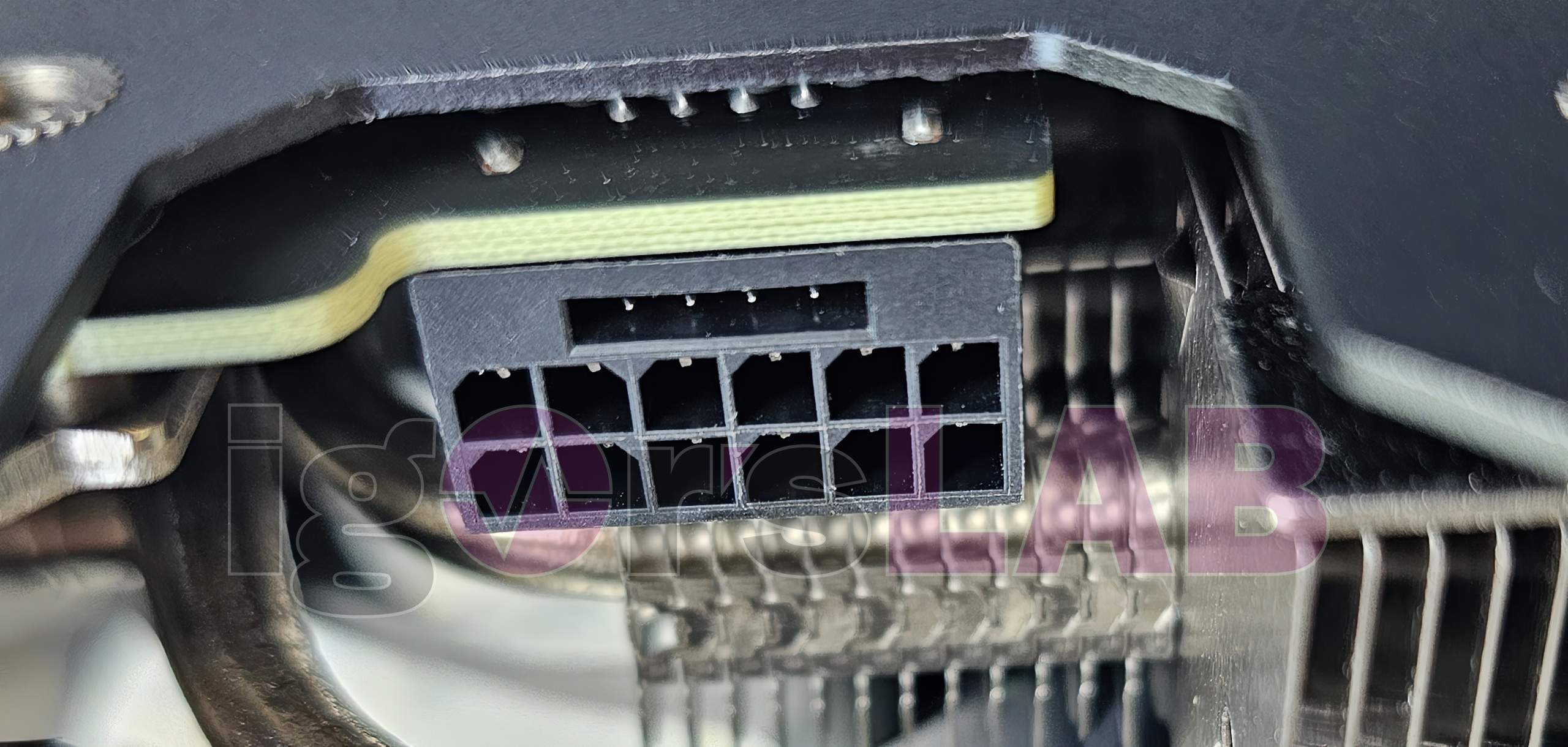
Let’s return to the Flip-Header, used in almost all Asus cards. While companies like Astron, Lotes, Amphenol, HYM, LST, and many others produce at least the original version of the 90° headers, Asus has custom-designed its own header, similar to the Flip-Header in the Mini-Fit format, and then used it as a so-called Flip-Header. Remember, in this design, the 12-volt supply lines are positioned externally and lengthened more than in the four sideband channels of the original.
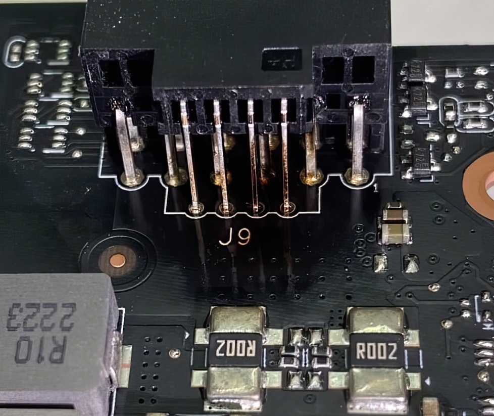
I’m pretty sure that this proprietary connector, not endorsed by the PCI SIG, comes from TKG. Considering the manufacturing quality, the design itself brings additional electrical, thermal, and mechanical problems. I’ve already extensively covered how these long-profile wires can bend, twist, or even shift backward through the housing in a detailed measurement series. I won’t repeat all that here, a link will suffice:
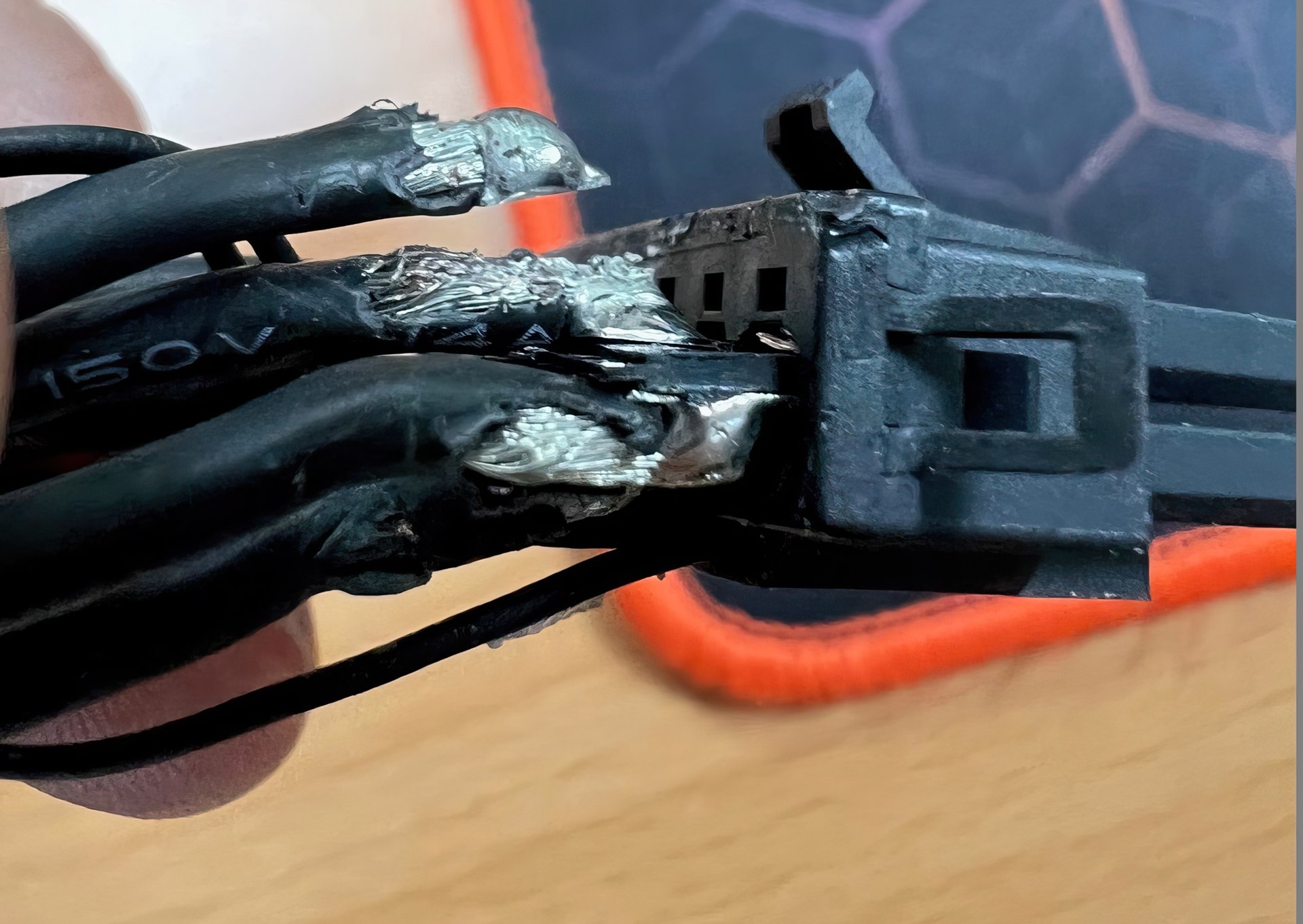
Satistically, Asus cards contribute disproportionately to the global damage statistics, which could involve around a thousand defective headers per month. When asking other board partners why they don’t use Flip-Headers, responses range from significant silence with raised eyebrows to a strong “We are not crazy.” There were rumors that Asus or TKG secured exclusive rights to this design, but one wonders who would willingly join this risky venture. So far, no one has.
Additional Temperature Problems Due to Heating from the Board
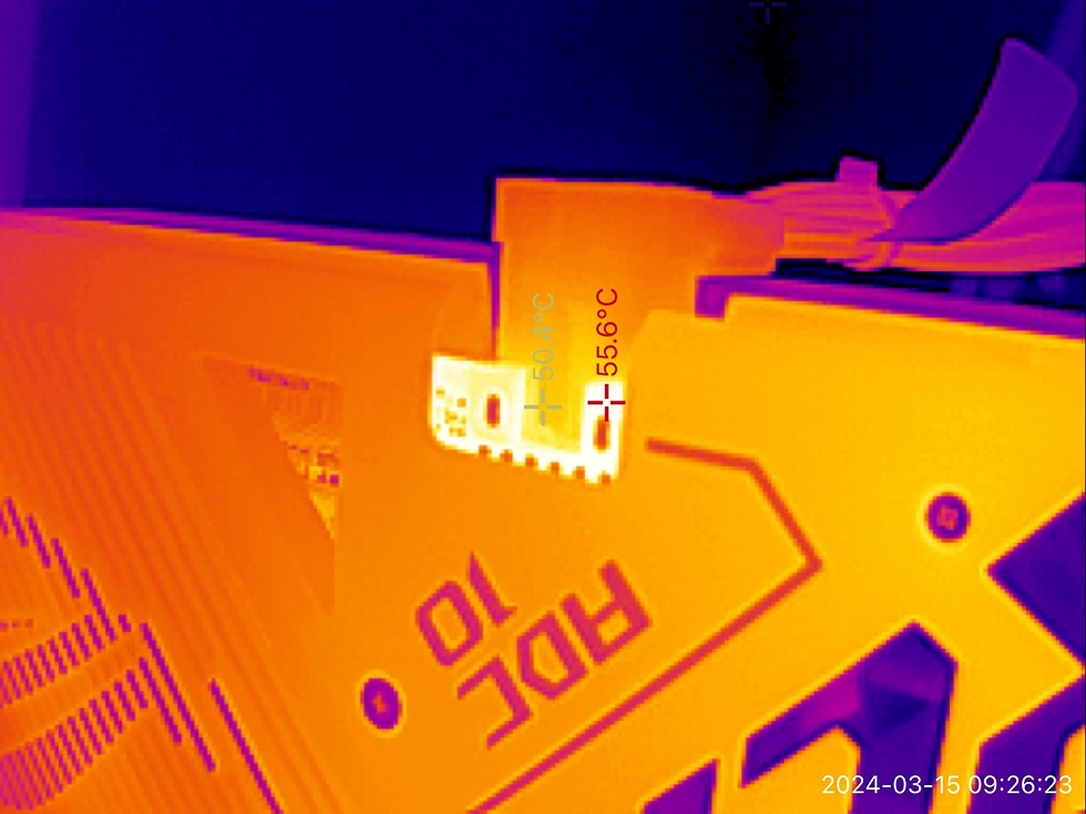
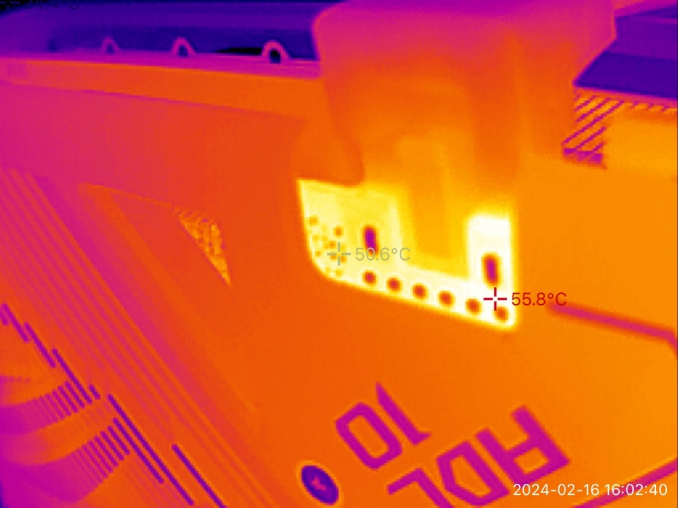
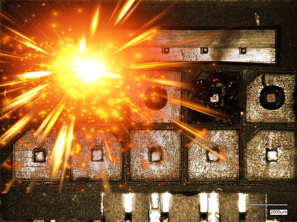
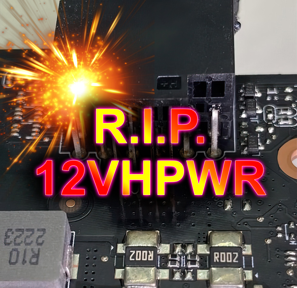
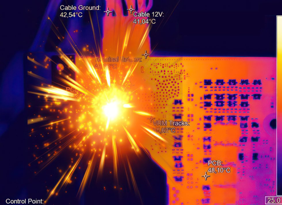
Especially Asus cards with a 180° rotated connector, where the 12-volt pins are directly in the vicinity of shunts (up to 100 °C) and the hot tracks from VRMs and coils, should have a different layout. The overly close positioning of components unnecessarily heats the contacts and the external 12V pins. That’s why I tested the pad behind this group, which can significantly lower temperatures in the header. Remember, the connector is specified to withstand up to 105 °C under continuous load. If the board temperature near the pins is too high, these are “preheated,” dramatically reducing the temperature window. With a delta of 20 degrees or even less, failure is inevitable.

One could mitigate this by thermally connecting the back of the board under the shunts and longitudinal coils to the backplate using good thermal pads, providing at least passive cooling. A reduction of just 5 degrees can prevent a “thermal ignition” of the contacts. However, it’s only one of many components, and multiple factors must coincide to cause a total failure.
Many Roads Lead to Rome – or to a Scorched Header
I see today’s article as a logical addition to previously published articles, supplemented with further exclusive insights, information, and drawings. It chronologically summarizes the development of this connector and accumulates the known sources of error. And no, it’s not a sensational report, but it is somewhat subjectively biased, as I find this connector too fragile for the intended continuous load.
And there is certainly not just ONE reason for occasional (but not always) failures. The PCI SIG has taken a big step in the right direction with the CEM 5.1 specifications, but still left many points open. While the proper fit can now be controlled and ensured through changed pins, and cable plugs and cables with specific bending radii and cross-sections have been more precisely defined, headers remain a potential cause of total failures. The pins and wires used need better standardization and subsequent quality control. This includes general problems in pin design and so-called Flip-Headers.
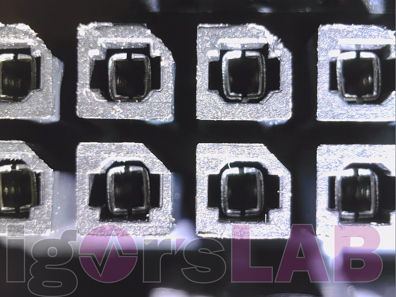
This concerns the basic design of the headers, the material (practical alloy instead of pure copper), the definition of the layer thickness of the galvanization, the processing of the wire pieces (cutting, bending), and their positioning (pressing) in the housing. Additionally, I miss strict guidelines for the minimum clamping area and spring pressure in the spring contacts. These are crucial factors primarily important for the right connection and should not be left to chance or individual manufacturers (which amounts to the same thing).
| Cause of error | Consequence or solution | Cause |
| Insufficient insertion of the cable plugs | Solved via pin lengths (sense pins, power pins), 12V-2×6 instead of 12VHPWR | User |
| Insufficient locking of the cable plugs | Solved via the specification | User |
| General plug design |
Sideband pins push the 12V pins upwards | Astron |
| Flip header |
Unnecessarily extended 12V profile wires, too close to the hotspots | Asus (TKG) |
| Incorrect insertion of the cable plugs | Can bend the header pins (especially the outer ones) | Users |
| Pulling off the cable plugs (lateral movement when loosening) | Can bend the header pins (especially the outer ones) | User |
| Excessive bending of the cables | Can bend the header pins (all) | User |
| Pins in the header too narrow | Insufficient clamping surface | Manufacturer |
| Twisted pins in the header | Insufficient clamping surface | Manufacturer |
| Position tolerance of the pins | Less clamping surface, contact problems | Manufacturer |
| Square wire of the pins rounded | Less clamping surface, contact problems | Manufacturer |
| Copper pins | Non-compliance with PCI SIG specifications | Manufacturer |
| Excessively high preheating of the pins on the PCB | Lower temperature window up to 105 °C | AIC |
| Inverse header | 12V pins too close to the hotspots of the PCB | AIC |
Conclusion
This connector, whether it’s the 12VHPWR or the more recent 12V-2×6, remains a rather fragile component, even though potential defects have been reduced with precautionary measures and improvements in standardization. However, one factor will always need to be included: quality deficiencies in the manufacturers of the connectors. Additionally, negative influences from the PCB layout of graphics cards often cause unnecessary preheating of the pins through the board itself. Graphics card manufacturers are responsible for increasing the distance of the pins from hotspots on the board or implementing cooling solutions.
My thanks again go explicitly to KrisFix, who has provided me with many defective connectors, as well as to the users who sent me their cards for examination. Furthermore, CableMod has contributed significantly to the gain in knowledge, as the countless test samples I was able to examine here have also led me to this conclusion.
And as I’ve written elsewhere: I’m essentially done with this connector, as there’s hardly anything else to investigate or optimize. And I’ll admit it: I still don’t quite like it because it operates too close to physical limits, making it extremely susceptible to potential influences, however minor they may seem. It remains a balancing act, right on the edge of what is physically feasible, without real reserves. When quality control also partially fails, that spells the end for the connector. It’s just not something you build. At least not like this.
- 1 - 2x EPS and over 700 watts? It could have been so easy!
- 2 - NVIDIA runs out of space with the Founders Edition
- 3 - GeForce RTX 3090 Ti: Playground for Ada and the 12VHPWR
- 4 - NVIDIA's mystic 12VHPWR adapter
- 5 - From 12VHPWR to 12V2x6 connector - user error de luxe?
- 6 - Flip headers, quality issues and a conclusion















37 Antworten
Kommentar
Lade neue Kommentare
Urgestein
Urgestein
1
Urgestein
Mitglied
Urgestein
1
Urgestein
Urgestein
1
Veteran
Veteran
Urgestein
Urgestein
Urgestein
Urgestein
Neuling
1
Alle Kommentare lesen unter igor´sLAB Community →