The king is dead, long live the king. Or the other way around: The findings of the last few months are finally taken seriously and the connector is modified, work is done on a new standardization and tests are carried out ad nauseam. The product is given a new name, although in the end it is only a further development that should have been expected right from the start. You don’t play with electricity, otherwise you’ll not only burn your fingers, but also your connectors. And so, instead of the burnt name and burnt cards, there is now simply a new name for an old acquaintance.

I am just so free and show you today, what is planned under the name PCIe Base 6 and will most likely come like this. And if we take a look at the newly introduced implementation hints, we also see that I was spot on with all my articles and videos about cable bending, crimping and soldering as well as lateral loads. To dismiss the problem with the 12VHPWR only sweepingly with the incompetence of the users may have been very convenient for NVIDIA one day before the announcement of the quarterly results, but it simply does not do justice to the complex matter. Which was to prove. I also know that NVIDIA is running long tests at Astron right now.
Today’s excerpt is from the upcoming CEM 5.1 specification of the PCI SIG as the basis for ATX 3.1 and also from a so-called draft, but it would probably be the first time that the manufacturers would not get their way here. So now let’s get to the details…
The 12VHPWR Connector goes and the 12V-2×6 Connector comes
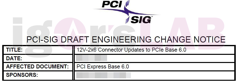
The new CEM 5.1 specification replaces the 12VHPWR connector with a new 12V-2×6 connector and will be less confusing as a base specification because it defines the measurement rules for maximum and sustained power in the same way as commonly used form factor specifications. This connector design is being introduced to support cards up to 675 watts. This allocates up to 600 watts to the connector and up to 75 watts to the mainboard slot (PEG). This is new, as CEM 5.0 previously set a maximum power of 600 watts for the sum of both connectors.

Along with that, the standard measurement method for maximum and sustained power has also been updated to match existing form factor specifications to provide the necessary consistency between specifications. But attention has also been paid to compatibility. One doesn’t see any impact on hardware that doesn’t support 12V-2×6. Minor impact, on the other hand, will be on hardware that has followed the base specification for implementing the 150W and 300W versions of 12VHPWR sense pin detection. However, I am not aware of anything relevant to the end user in the graphics card sector in this regard.

You also don’t see any impact on software implications unless the software supports the CEM form factor. Software that uses the Power Budgeting Sense Detect Register will need updates to reflect the new defined encodings. Software that uses the Connector Type field will need updates to support the additional connector type encoding. But again, nothing relevant is known so far for graphics cards and power supplies. It hadn’t been implemented anywhere so far anyway. Configuration memory tests might have to be updated to not mark expansion cards using the new encodings as faulty.

The new 12V-2×6 power connector also provides up to 55 A of continuous current to power the expansion card with a maximum of 600 W on a 12 V aux rail. The power requirements for the connector and cable assembly are as follows:
- Current rating of current pins (sideband contacts excluded): Minimum 9.2 A per pin/position with a limit of 30 °C T-rise above ambient temperature conditions at 12 V dc with all twelve contacts activated.
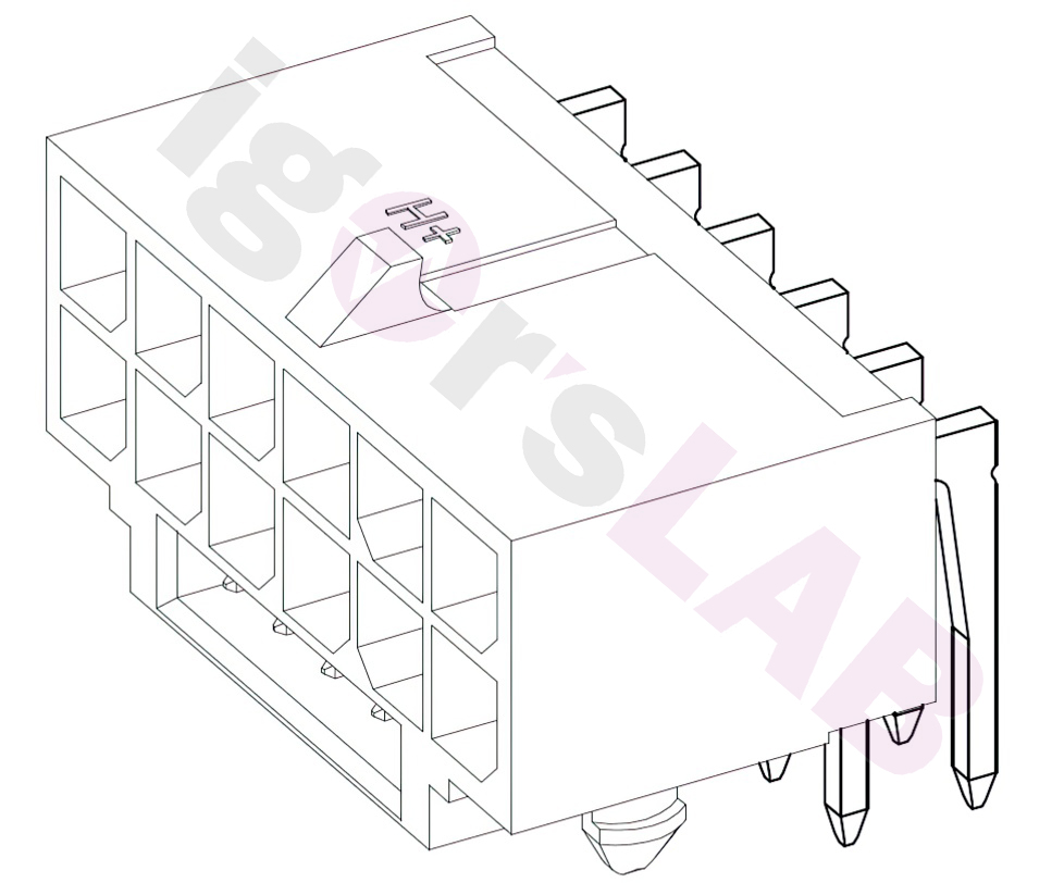
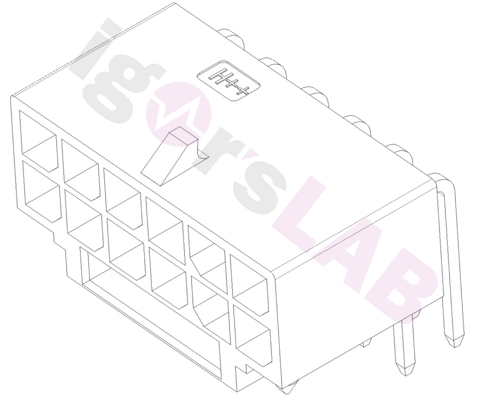
- The connector body shall have a label or embossed H mark to indicate support of 9.2 A/pin or greater. See illustration above for approximate location of mark on 12V-2×6 Right Angle (R/A) header.
- Due to variations in contact resistance, a single pin may see more than 9.2A of current depending on uneven cable contact resistance, but the total current for the assembly must not exceed 55A RMS in either direction. This also addresses measurements and requirements for contact resistance variability.
- Cable assembly integrators must ensure that the assembly, including 16 AWG wires and pins, meets the minimum current requirement and maximum temperature rise as specified above for their implementation.
- Locked connector retention force: minimum 45.00 N when the connector is pulled axially
In the next pages, we will then see exclusively what should change in detail and what must be taken into account for safe operation.


182 Antworten
Kommentar
Lade neue Kommentare
Urgestein
Urgestein
Urgestein
Urgestein
Urgestein
Urgestein
Urgestein
Veteran
1
Veteran
Urgestein
Veteran
1
Urgestein
Urgestein
Urgestein
Veteran
Mitglied
Veteran
Alle Kommentare lesen unter igor´sLAB Community →