


Important implementation notes for the 12V-2×6 cables regarding quality and workmanship
To avoid unnecessary stress on the crimp contacts, cable bundles should not be bent immediately after exiting the back of the connector. The cables should not be stretched or restricted in any way. The IPC/WHMA-A-620 standard prescribes practices and requirements for the manufacture of cable, wire and cable assemblies. The standard describes materials, methods, tests, and acceptance criteria for the fabrication of crimped, mechanically secured, and soldered connections, as well as the associated assembly activities (appropriate fastening/retention criteria) associated with cable and wire assemblies.
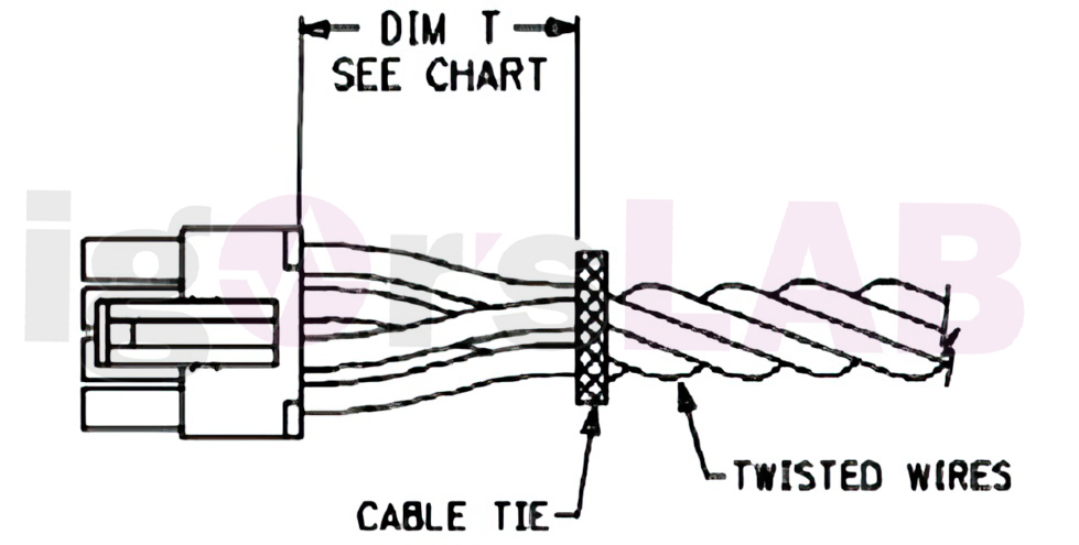
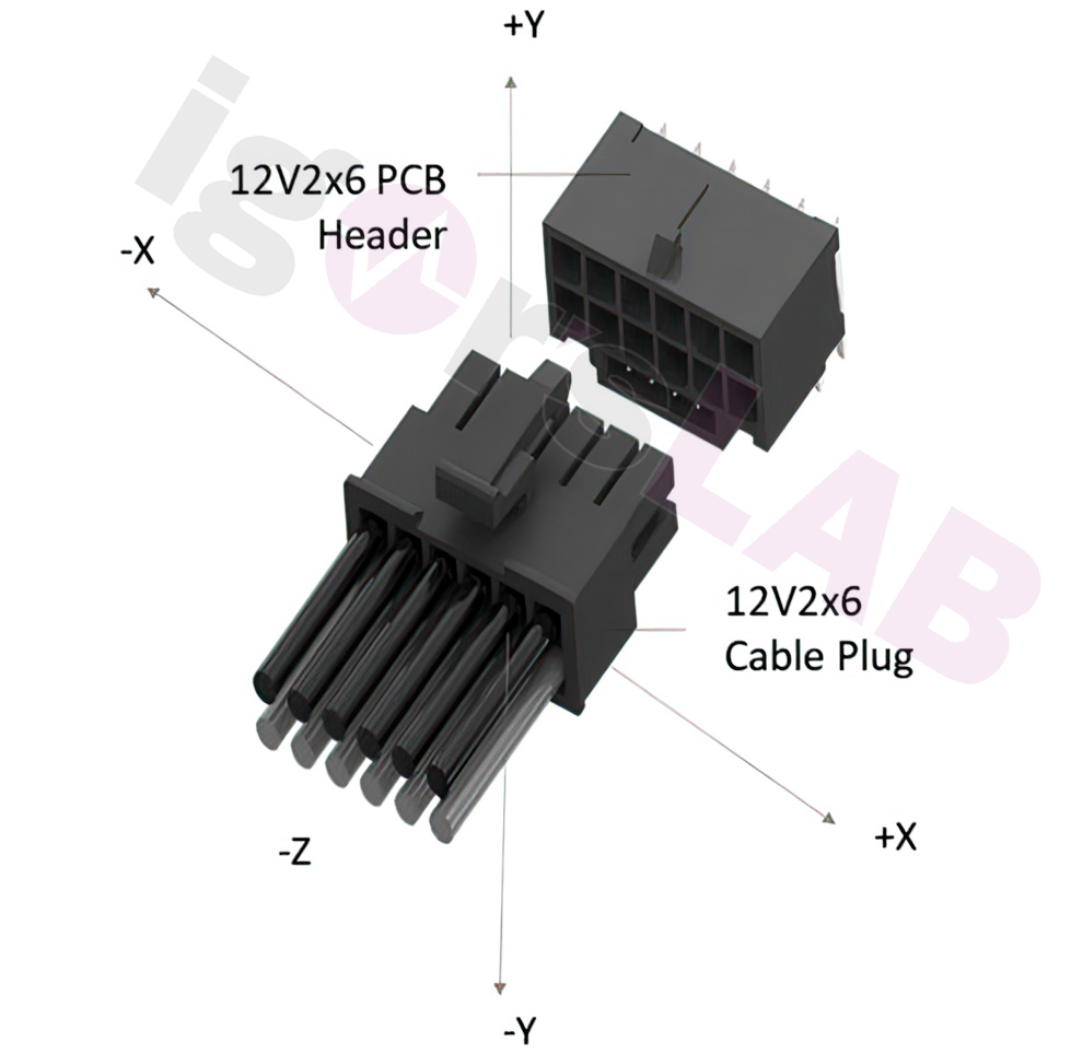
Variability in contact resistance within a cable assembly causes current imbalance between contacts and may cause individual contacts and/or wires to exceed the current per pin specified in Section 9.1. In addition, this current imbalance can be increased by cable bending and/or side loading of the cable assembly that is connected to the expansion card. The specific wire, connectors, and manufacturing process used for a cable assembly must be designed to accept the current imbalance due to variability in contact resistance and side loading. Lateral load is defined here as a load applied in any direction perpendicular to the housing bodies as defined in Figure 9-10.
I also remind you in this context that I addressed and addressed exactly these circumstances of side loading both in my research at the time and in the articles and videos. The fact that this important circumstance is now also included in the specifications after many indications and measurements confirms once again that the pure generalization to user errors simply cannot do justice to the problem. This also applies to my investigations into crimping or soldering and the design of the cables.
Measurements and test procedures
For better understanding, I briefly explain what Low Level Contact Resistance (LLCR) is all about. LLCR is used in combination with several other tests to track the overall performance of a part under certain conditions. Specifically, it involves measuring the electrical resistance of a system under test with an open circuit voltage. The voltage is low enough to not disturb thin films that might exist in the contact area.
The current level is also low enough to ensure that the device under test does not heat up and melt asperities. In other words, the current is low enough that oxide films are not destroyed and skew the results. LLCR is measured in milliohms (mΩ), and a normal LLCR reading is between 5-15 mΩ for a board-to-board system. For the test, the voltage is limited to 20 mV and the current to 100mA. A change in R greater than 15 mOhm is typically considered a failure.
To measure low level contact resistance and verify that a coupled connector head and cable assembly design can control contact resistance under side loading conditions, the following methodology is suggested:
- Attach the expansion card connector to a fixture.
- The LLCR of the cable assembly is measured from the footprint of the socket on the top of the expansion card PCB to 50mm from the point where the wire leaves the body of the connector. The purpose of checking the measurement point is to ensure that the wire length and its contribution to contact resistance are repeatable. This does not imply any limitation on the specific cable assembly implementation
- Perform 30 mating cycles between the connector and the cable assembly
- Logging the LLCR of each conductor of the cable assembly in the unloaded state.
- Use a side load of 20 N in each of the directions defined in the above. The load must be applied to the cable bundle and beyond any cable ties or strain relief features of the assembly, if any. Note the LLCR of each conductor once the measurement result reaches a stable value.
- Calculate the average contact resistance of pin groups 1-6 and 7-12 independently for each side load condition
- The result for LLCR must not change by more than 50% from the average of that pin’s respective group under any test condition. A maximum LLCR of 6 mOhm/contact is specified as the upper limit for each conductor.
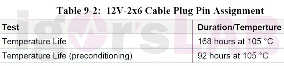
Temperatures
There are also new versions regarding temperatures and limits. If you add the heat development of the board (shunts with more than 100 °C!) and the possible heating of the pins by an external influence from the side of the board and not only by the flowing currents and the contact resistance, then you can certainly draw the conclusion from the specified temperature limits for the durability, that especially air-cooled cards should be designed differently in the area of the power connection.
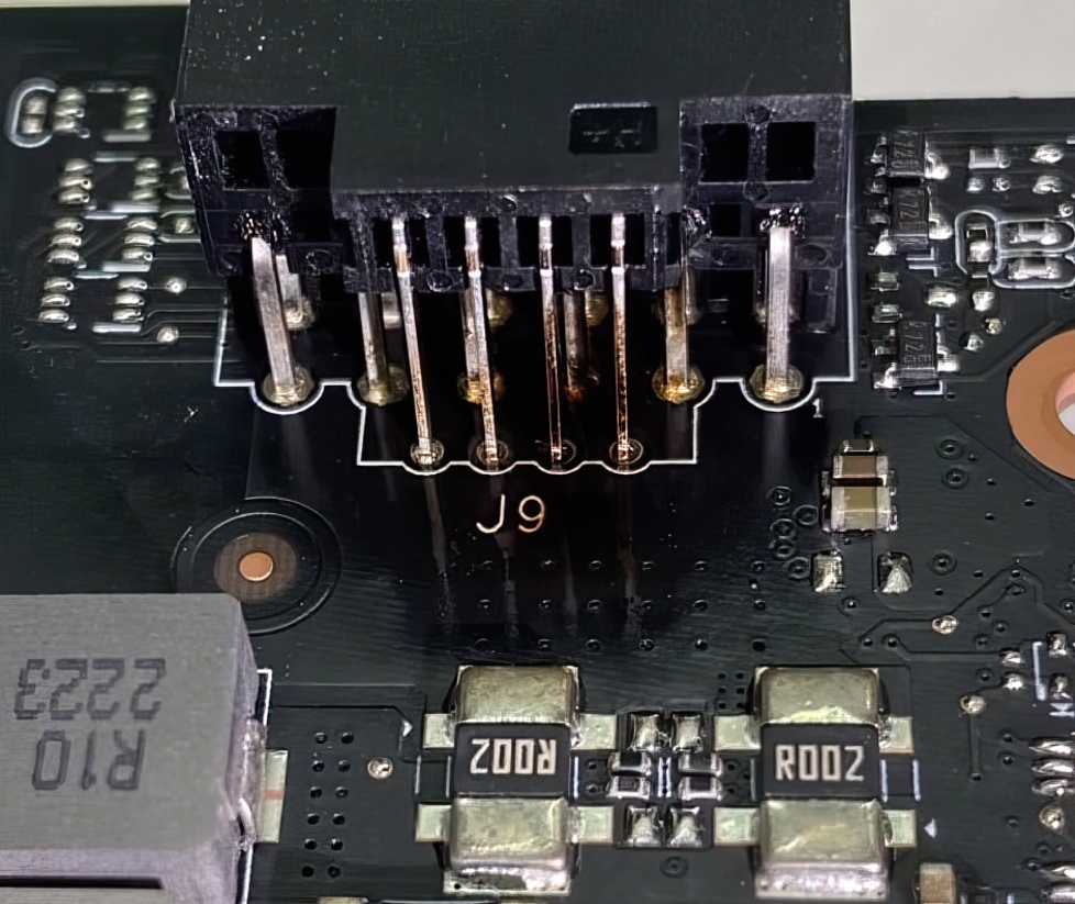
My own conclusion: Especially cards with 180° rotated connector, where the 12 volt pins are directly in the catchment area of the shunts and the hot tracks from the VRM and the coils, should really be designed differently here in the layout. The much too close positioning of the boards heats up the contacts and thus also the 12V pins completely unnecessarily. That’s why I tested the pad with behind this board, which can lower the temperatures in the header significantly.
Summary and conclusion
The changes presented today are not final yet, but very much will certainly not change. For the fraction of 6 2-pin lovers, however, the news that the new 12V 2×6 connectur will also be specified for expansion cards up to 150 watts or up to 300 watts is certainly a disappointment. And otherwise? The resetting of the sense pins to detect a safe insertion should have been implemented in the first revision of the 12VHPWR connector. Also the missing specification of the lower watt classes and the now necessary rework in the software area are actually completely superfluous, had it been done right from the start.
Also, all the handling recommendations are a clear expression that the technology has its pitfalls if you don’t really install everything according to specification. In my opinion, the PCI SIG and all the companies involved are clearly to blame for the whole mess, and not the end user, who is supposedly too stupid. As the saying goes, many cooks spoil the broth, even if it’s just a plug connection. After all, the difficult thing is to make the supposedly simple as user-friendly as possible.
If you want to se my German video, here is it:
Or read all the last articles to remember the details:


170 Antworten
Kommentar
Lade neue Kommentare
Urgestein
Urgestein
Urgestein
Urgestein
Urgestein
Urgestein
Urgestein
Veteran
1
Veteran
Urgestein
Veteran
1
Urgestein
Urgestein
Urgestein
Veteran
Mitglied
Veteran
Alle Kommentare lesen unter igor´sLAB Community →