


Those who are now beating up on the new 12VHPWR (although I don’t really like the part either) may generate nice traffic with it, but they simply haven’t recognized the actual problem with the supposedly fire-hazardous and melting connections or cables. Even if certain YouTube celebrities are of a different opinion because they seem to have found a willing object of hate in the 12VHPWR once again: This connection is actually quite safe, even if there are understandable concerns regarding the handling.
However, the “safe” is only valid if e.g. the used supply lines from the power supply with “native” 12VHPWR connector have a good quality and 16AWG lines or at least the used 12VHPWR to 4x 6+2 pin adapter also offers what it promises. Which brings us directly to the real cause of the cases that occurred: It’s the adapter solution exclusively provided by NVIDIA to all board partners, which has fire-dangerous flaws in its inner construction!
Our investigation has now also put NVIDIA on the map, but not officially yet, only in their own board partner circles.
Adapter gate? NVIDIA briefs all board partners this morning and makes damage an absolute boss issue
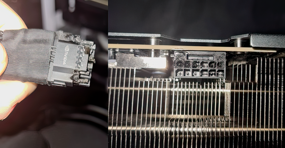
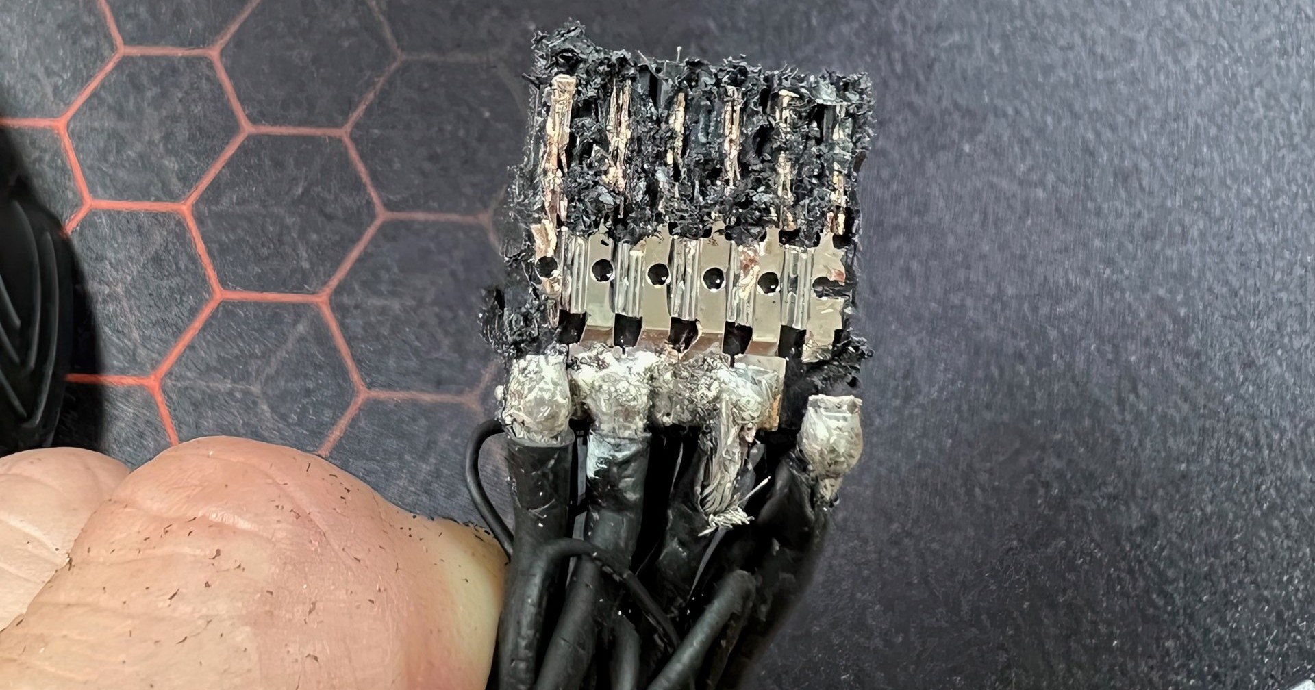
Let’s first take a quick look at the typical error pattern that occurs when such an adapter triggers a defect, before we start searching for clues inside the accessories distributed by NVIDIA. And before you start beating up the PCIe 5.0 connector, even a layman can see from the error pattern and the load distribution what or where the actual trigger must have been.
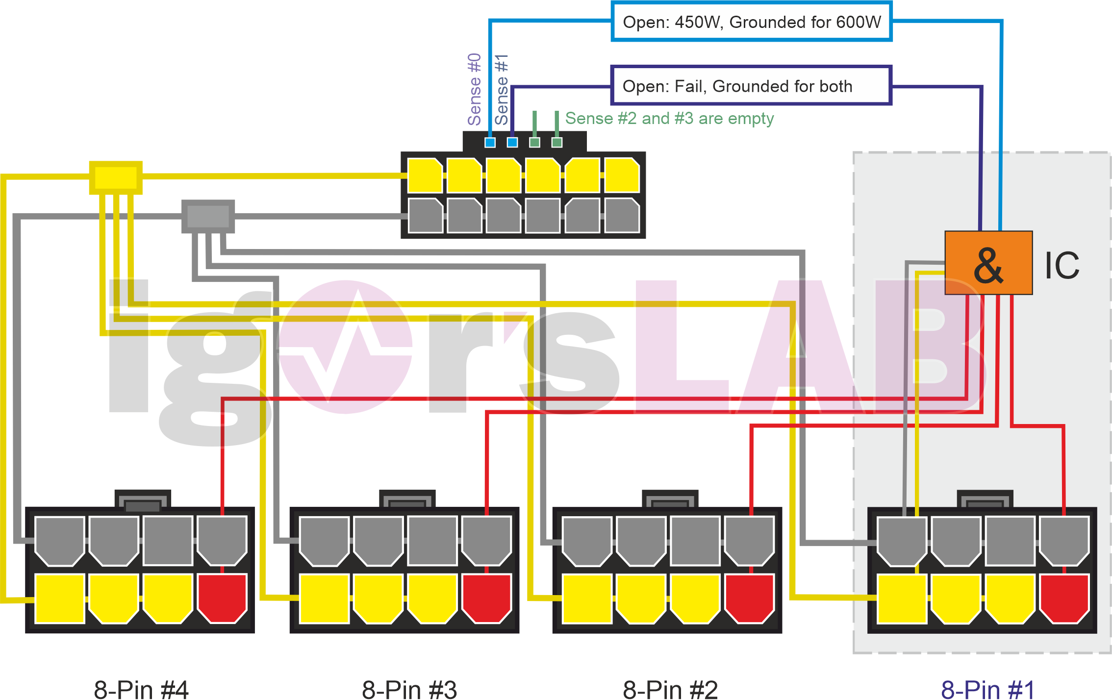
As a reminder, I’ll now also briefly show you the block diagram of the special NVIDIA adapter, whereby we are only interested in the upper six yellow connections of the connector including the bridge here. Electrically, all 12V pins are still connected to each other and then also once again to the four feeding wires:
The sad truth lies in the plug, not in the form factor
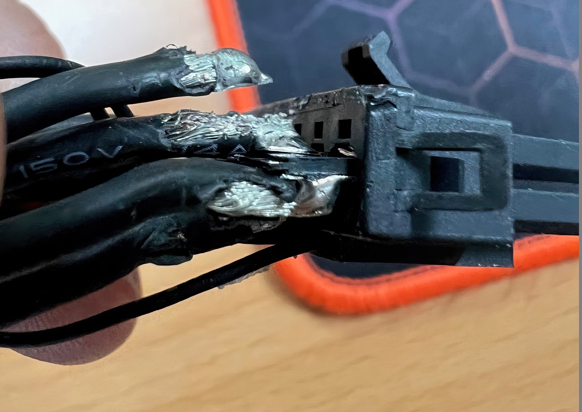
I’m pretty sure that NVIDIA itself doesn’t know or didn’t know exactly what kind of contact party the supplier is having inside the molded connector. Otherwise, this part should not have been approved in this form. When you remove layer after layer, something gradually emerges that you would have been better off not seeing in the first place:
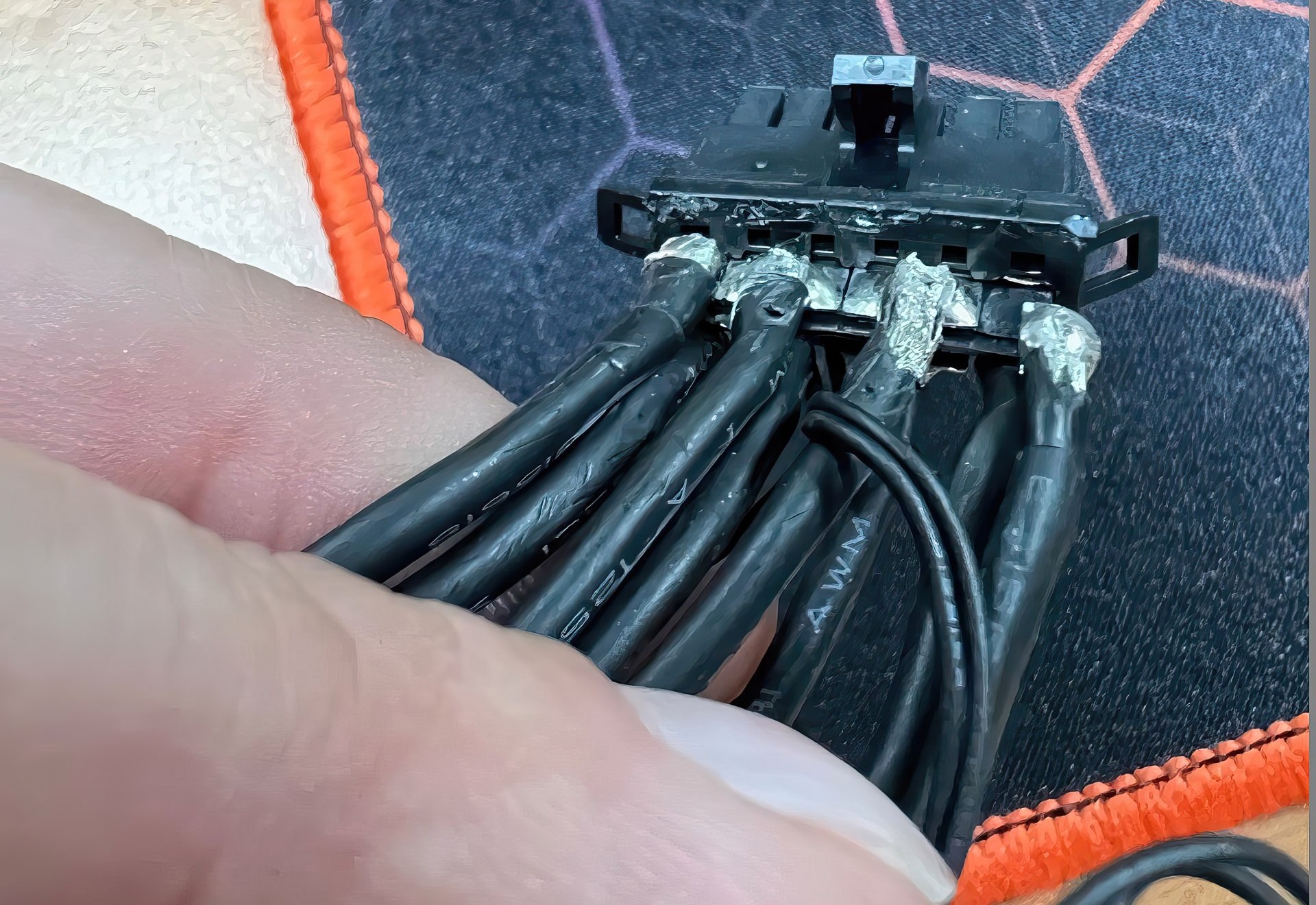
A total of four thick 14AWG wires are distributed over a total of six contacts, with the two outer leads soldered to one pin each and the two middle leads soldered to two pins each. The solder base is a mere 0.2 mm thin copper base with a width of 2 mm per incoming wire, which then results in 4 mm per pair for the middle connections. Soldering one or even two 14AWG wires to it is very sporty. Confucius says succinctly, “What is cast in cannot be seen, and what cannot be seen cannot be broken.”

But just carefully lifting off the enveloping layer causes the thin plate to tear immediately. With which we also see that bending the cables at the connector in the housing can cause such damage. Wobbly contacts or unsafe bridges, as well as increased resistances as a result of such actions are highly dangerous at these current strengths and very quickly lead to exactly the errors that we have already seen above. And you can now also see why especially the two outer contacts of the connector are affected. The scorched socket on the card is then only the consequential damage.
However, you can cut the plug open even further and see what exactly is inside. Because this detail is also highly interesting for the cause research. We see that the contacts in the connector are once again interconnected. If, in the worst case, the outer two wires break off, the entire current in the middle flows through the remaining two wires and is only then distributed in the plug again. But even this “foil” is thin and does not replace a real 14AWG. The fact that this then becomes really hot does not have to be explained separately….
That’s the right way to do 12VHPWR!
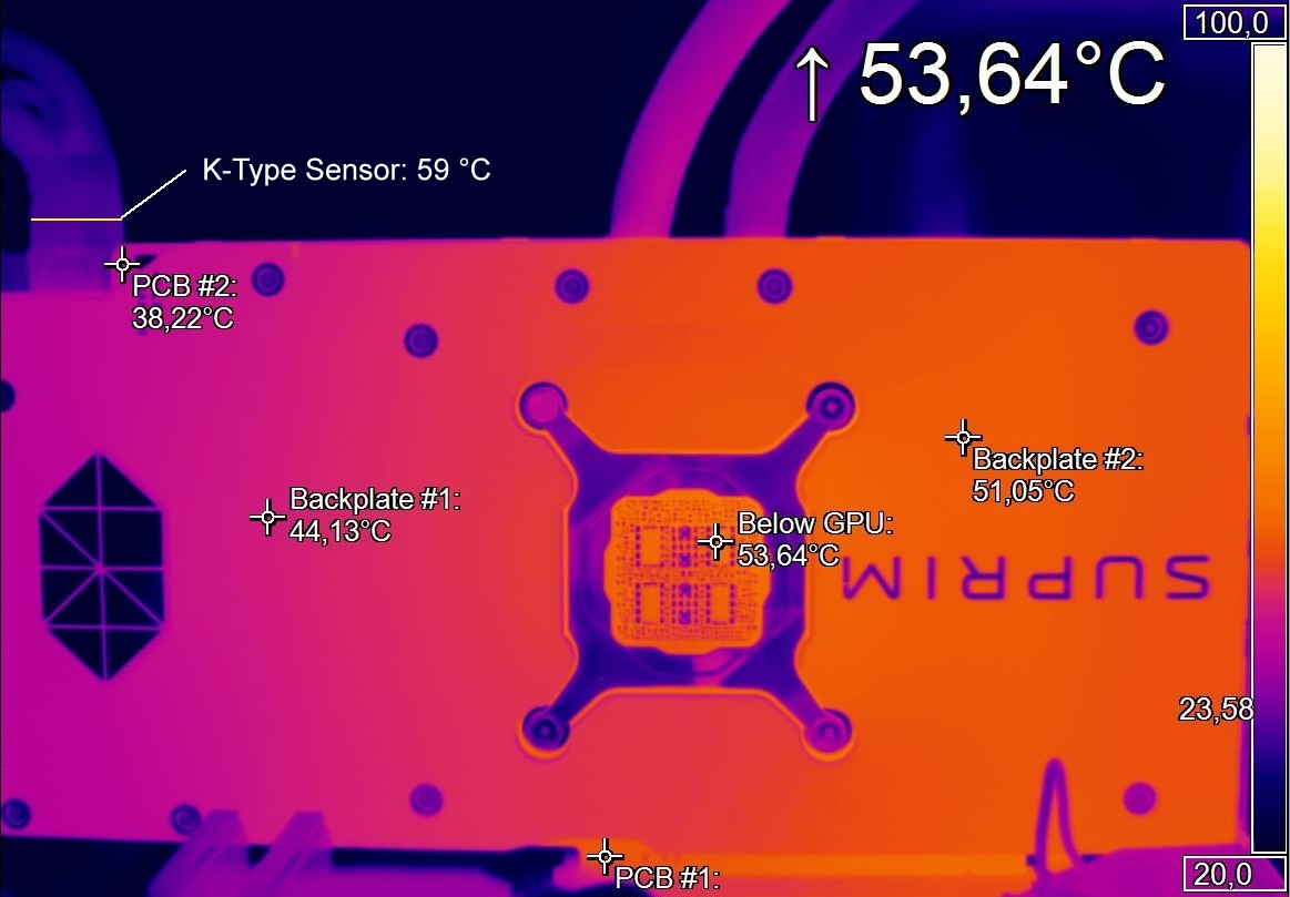
You can like the connection or not, but you also have to stick to the facts and the truth. The native 12VHPWR cables of the better power supplies show that it can be done differently. Incidentally, I also measured the 12VHPWR using resistance sensors and was able to determine absolutely unsuspicious temperatures (picture above). At plenty of 530 watts it was under 60 °C and even the maximum temperature of just under 68 °C I could only prove after an hour with 600 watts in the stress test. But definitely nothing melts there yet!
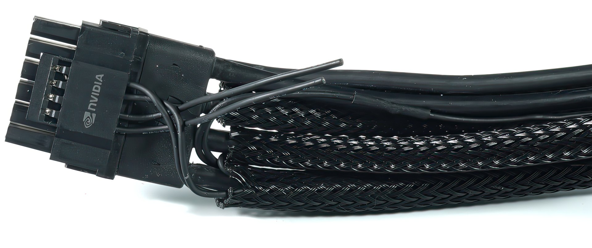
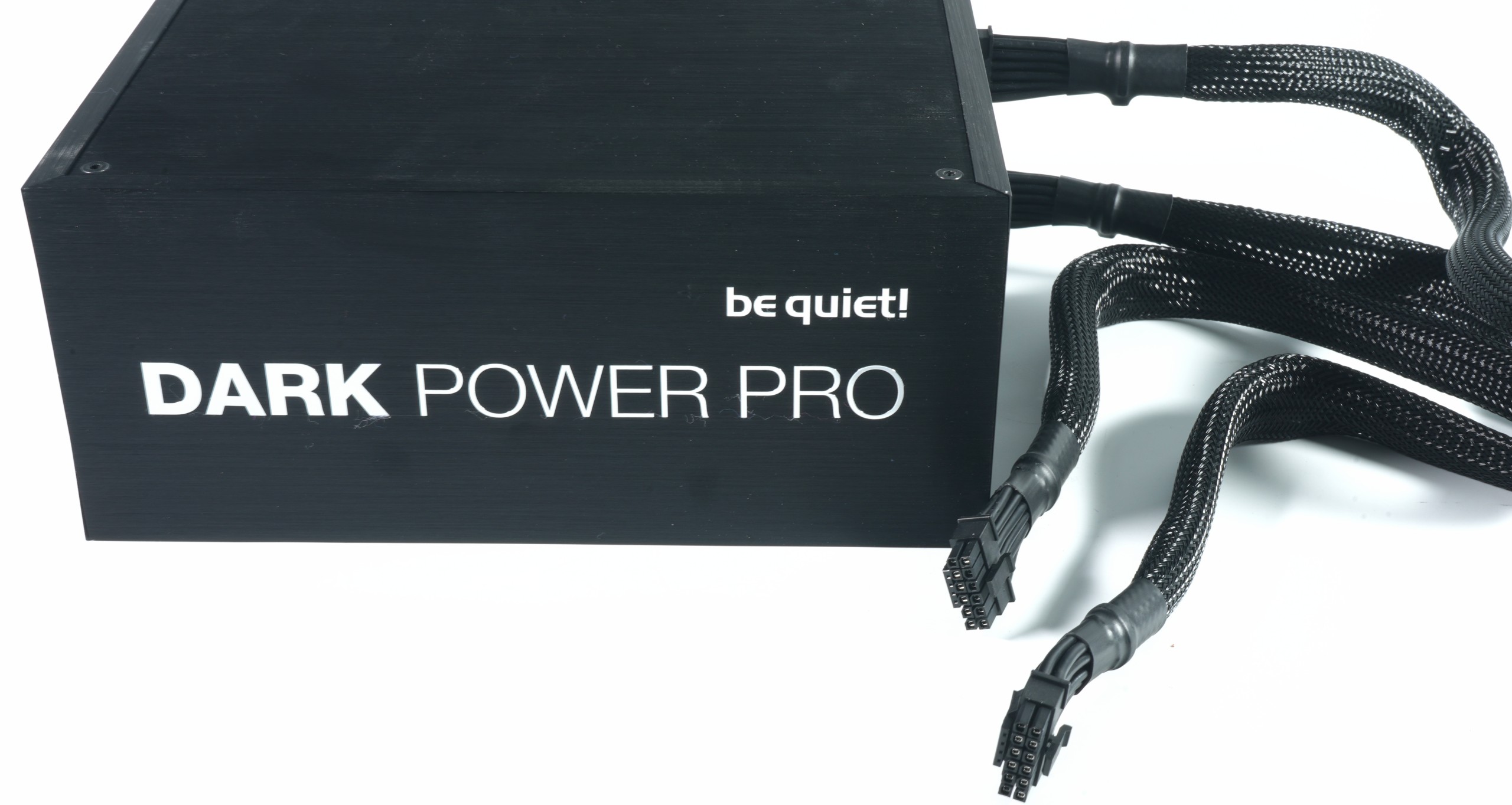
A good example of a functioning connection are, for example, the two 12VHPWR cables of the new be quiet! Dark Power Pro 13, which I still show here as an example. Because there you don’t have to do the balancing act with the voltage bridges, but spend each pin its own 16AWG line. Sure, 12 thick wires in one cable is not that sexy now either, but it is at least an accurate and clean solution. I also snapped these cables right at the connector several times and did much of my testing for the GeForce RTX 4090 as well as the Intel Core i9-13900K in the lab with them on the redundant test system.
Summary and conclusion
The overall build quality of the included adapter for the GeForce RTX 4090, which is distributed by NVIDIA itself, is extremely poor and the internal construction should never have been approved like this. NVIDIA has to take its own supplier to task here, and replacing the adapters in circulation would actually be the least they could do. I will therefore summarize once again what has struck those involved (myself included) so far:
- The problem is not the 12VHPWR connection as such, nor the repeated plugging or unplugging.
- Standard compliant power supply cables from brand manufacturers are NOT affected by this so far.
- The current trigger is NVIDIA’s own adapter to 4x 8-pin in the accessories, whose inferior quality can lead to failures and has already caused damage in single cases.
- Splitting each of the four 14AWG leads onto each of the 6 pins in the 12VHPWR connector of the adapter by soldering them onto bridges that are much too thin is dangerous because the ends of the leads can break off at the solder joint (e.g., when kinked or bent several times).
- Bending or kinking the wires directly at the connector of the adapter puts too much pressure on the solder joints and bridges, so that they can break off.
- The inner bridge between the pins is too thin (resulting cross section) to compensate the current flow on two or three instead of four connected 12V lines.
- NVIDIA has already been informed in advance and the data and pictures were also provided by be quiet! directly to the R&D department.
Actually, I wanted to do something completely different today, but this correction was more important to me. Blanket panic and gloating are really bad advisors here when it comes to introducing new standards. That AMD has not (yet) joined the plug change was shown in my news about one of the upcoming board partners. But if you, like NVIDIA, take such a radical step, then at least the included accessories should work properly over after a little bending and ensure a safe, stable operation of the graphics cards.
My thanks also go to Christian Rex from be quiet! whose pocket knife was faster than my Dremel.
Source: Own, be quiet!


219 Antworten
Kommentar
Lade neue Kommentare
Mitglied
1
Veteran
Urgestein
Veteran
Urgestein
Mitglied
Urgestein
Veteran
Mitglied
Neuling
Moderator
Urgestein
Veteran
Neuling
1
Urgestein
Neuling
Mitglied
Alle Kommentare lesen unter igor´sLAB Community →