


Today’s article is the result of several months of laboratory work, extensive measurement series, development work, and constant cross-checking. The matter of the 12-volt connectors is unfortunately so complex that I had to look for a new approach to complete the picture. And no, there isn’t THE one cause, but always a causal chain of several factors. That is what ultimately makes it so difficult, but at the same time, it’s a challenge to do more than just wildly speculate. And interestingly, my first articles on the topic almost seamlessly fit into what I have added new today.
Important Preface and Definition of Terms
This time I didn’t take the easy way out because it would be completely unfair to blame the user alone for destroyed hardware. When one has the ability to track the changes of the PCI SIG and the switch from the 12VHPWR to the 12V-2×6 connector, including all the detailed annotations, can use contacts with connector manufacturers, and also has precise measurement capabilities, a very interesting, completely new picture emerges. Because there are also causes of failure of this connection that have not been considered, in which the supposedly “stupid” user is only a small part of the truth.
The fact is that manufacturing tolerances, material, and overall quality of workmanship form a certain focus of the problem. And it has become clear after now more than 50 defects examined here in the lab that almost always a combination of several causes has led to total failure, not just one. Even if the story of incapable users just before NVIDIA’s announcement of quarterly results suited the provider (quite coincidentally), it helps no one, not even NVIDIA, as it was probably a hasty rush job.
This whole story is so complex that one must be very careful with attributions of blame. And so, for weeks, I have also been examining a component that has, strangely enough, hardly been written or speculated about. The supposed “socket” that sits on the graphics card is actually, technically speaking, a male connector with the male pins. What we then plug into it is actually a socket, because the spring contacts represent the female parts of the connection. Therefore, I will consistently use “header” when referring to the part with the pins on the graphics card and the counterpart to be plugged in, as “cable plug,” as the PCI SIG does. And even though both together actually constitute a clamping plug connection, I will simply refer to it as “connector” for the sake of simplicity.
Differences between CEM 5.0 and CEM 5.1 and New Details
The PCI SIG and its participants seem to have gone through a continuous “learning by doing” process concerning certain details. To avoid user errors, they now use retracted sense pins and forward-extended power pins to create more contact surface. This may be helpful if the user does not possess special skills for plugging in, but that is known and NOT the topic today. I will summarize these other things at the end to complete the picture. So today, it will primarily be about the pins on the graphics card header and not about what the user exactly plugs in there. First, let’s look at the older CEM 5.0 and the 12VHPWR header in its original form:
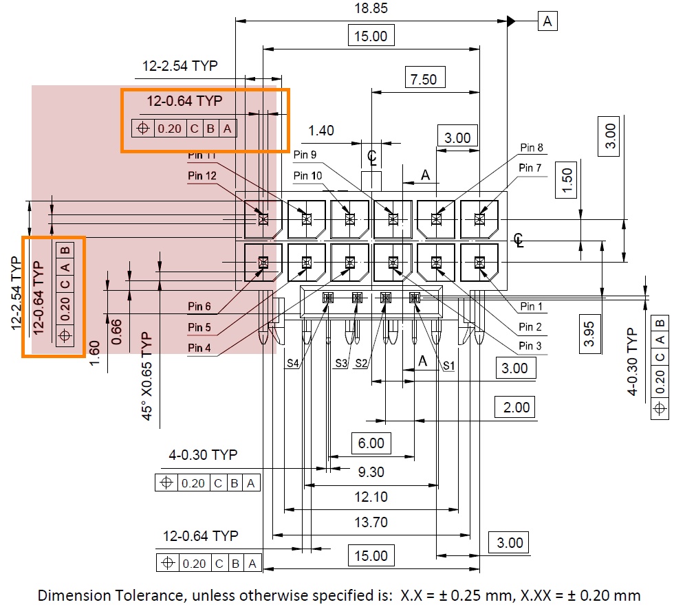
We see that the 12 pins (6 for 12 volts and 6 for ground) are each specified as square with 0.64 mm outer length or height. The tolerances for this detail are completely missing (and not only for this). That can quickly become a problem, but now let’s take a look at the current version of the headers on the graphics cards:
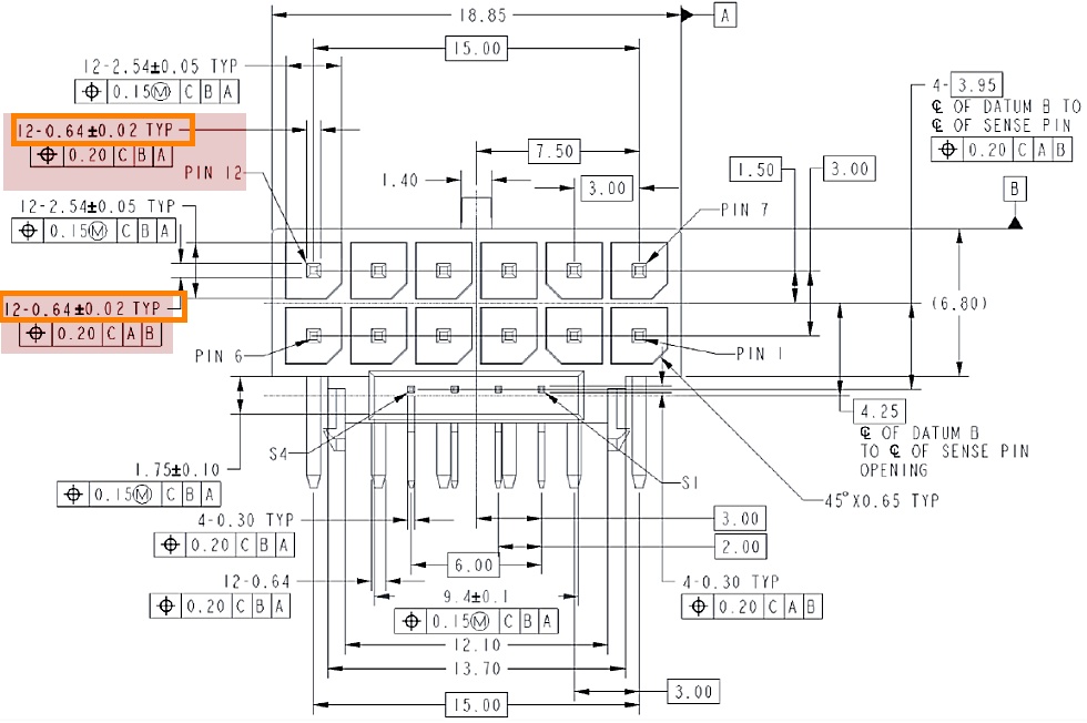
Well, what a coincidence! Now they have also set the tolerances, which have been constantly demanded (not only by me), that apply to the dimensions of the pins! However, important details such as the twisting, the radii of the edges (which are not round), as well as the position tolerance are still missing. For the latter, according to the drawing, a very generous 0.2 mm would be set, which can definitely be a source of error. But more on that in a moment. But we also see that it’s not only the type of spring contacts (whether Astron or NTK) that matters, but also the actual clamping area resulting from the pins and their size and positioning, as well as possibly insufficient contact pressure! By clamping area, we mean the area where the intended current flow can actually take place, and unfortunately, this area is still missing in all documentation, as is the prescribed contact pressure. Here, unfortunately, each connector manufacturer cooks its own soup, and one runs against a wall of silence.
One must not forget: With the now established tolerance range for the pins, these may have a side length between 0.62 and 0.66 mm for a specification of 0.64 mm. But this includes the absolute ideal case that these pins are absolutely rectangular and also always completely straight. Just by the production (usually a punch and die process), a slight twist can occur. This is not bad per se if you calculate the tolerances for it and the socket with the female contacts has been designed for it. However, this does not seem to be the case at the moment, as the PCI SIG’s new specifications suggest.
Update and Technical Note for Outsiders
A positional tolerance of 0.2 mm relative to 2 axes means that you are allowed a maximum deviation of 0.07 mm per axis. Why is this the case? Such tolerances are squared per axis. But then the question arises how connector manufacturers can implement this: Can they really work so precisely in a process-capable manner? You may believe it, but you don’t have to. What are actually missing from the drawings of the PCI SIG are the following dimensions:
- The perpendicularity of the pins relative to reference C
- The parallelism of the pin surfaces to A and B (regarding twist)
- The flatness or surface contour of the pin clamping surfaces (concerning camber)
- Edge break specifications (radii on the pins)
- The minimum clamping surface for the Cable Plug (minimum opening dimension in the unclamped state), ensuring the clamping or contact surface for electrical current flow.1
I had already written the rest. Furthermore, one should really consider whether it is possible to move from the classic ABC reference system to a symmetric dimensioning system. It’s perfectly acceptable that the dimensions of the part to be inserted are made tighter, as this prevents any jamming. However, the general omission of everything concerning the spring contacts has been retained. Personally, I find this dangerous because it can certainly introduce new potential sources of error. I have conducted numerous test series and have also checked the materials and surfaces. It’s somewhat disheartening that some manufacturers are not very precise with tolerances or consistently operate at the very lowest end of what is permissible. When you take third-party products like the CableMod adapter or even the header soldered onto defective cards by KrisFix, both the cable plug and the respective headers align exactly with the standard values of CEM 5.1, WITHOUT fully exploiting the tolerances to the downside.
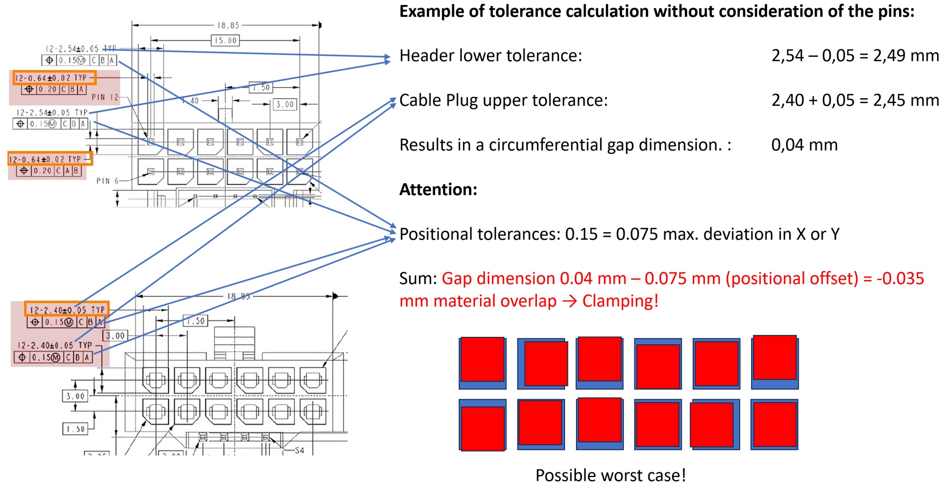
Update (2) and Positional Tolerances
Thanks to Fritz Hunter for the rapid graphics that highlight the nonsense with these positional tolerances once more and calculate that with such specifications, even clamping connectors can be a possibility (click to enlarge):
Test system and test objects for the measurement
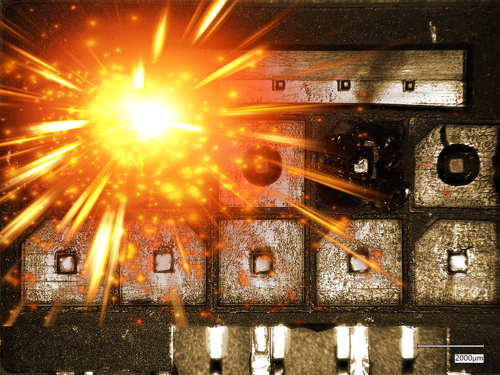
It has always been the case that testers have primarily focused on the outer burnt contacts when it came to defects and severe criticism. But at least since users have been sensitized to properly inserting and angling the cables, the picture has changed slightly. For the following comparison, I found a total of four different types from which I could make little piles with the defective headers available to me. In this context, it’s also interesting to note the pattern of failure at the bottom of the headers and the backside. Most of the headers in my “corpse” collection are so-called inverse headers, like those used by Asus (but not exclusively). With this variant, the locking latch and the 4 sense pins face away from the board, effectively upwards. And it is these headers that I will use for the following examinations because I have the most of them. A bit of statistics and reproducibility can never hurt.
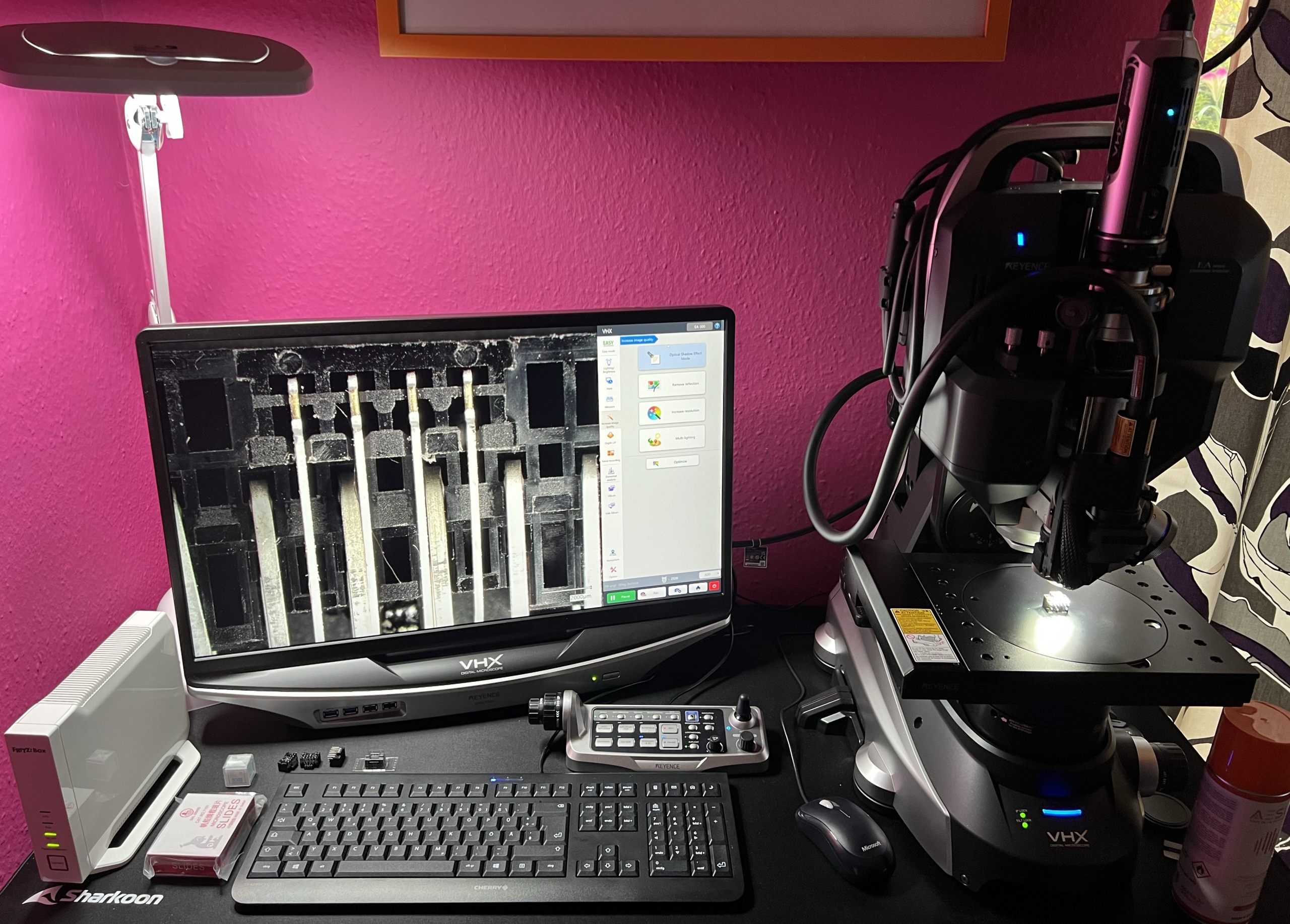
The Keyence VHX-7000 system coupled with the AE-300 from my own lab is a versatile 3D profilometer, and the powerful microscope (max. x2000) can also be used perfectly for such examinations with its HDR function, automated lighting scenarios, and immense depth of field. Furthermore, it serves for material analysis, for which I do not have to use a complex SEM + EDX. Vacuum? I don’t need that anymore, and it saves a lot of time. As long as one knows what one is getting into and where the limits of the used method lie, it really works well. That’s exactly what we need today as well.

- 1 - Introduction, Important Preface, and the PCI SIG
- 2 - Material Analysis with a Key Finding
- 3 - Damage Level 1: Barely Visible or Minor Damage
- 4 - Damage Level 2: Moderate to Major Damage
- 5 - Pin Width, Twisting, Positional Tolerance, and Clamping Surface
- 6 - Summary, Overview of Most Causes, and Conclusion


504 Antworten
Kommentar
Lade neue Kommentare
Urgestein
Urgestein
Urgestein
1
Urgestein
Veteran
Urgestein
Mitglied
Urgestein
Veteran
1
1
Mitglied
Urgestein
Veteran
Veteran
Veteran
Urgestein
Urgestein
Alle Kommentare lesen unter igor´sLAB Community →