


Summary
I view today’s article as a logical addition to the already known sources of error, not as a sensational report, especially since it addresses the header that has so far received little attention. But it is definitely not the only reason why failures sometimes occur (but not always). The PCI SIG has already made a significant step in the right direction with the specifications of CEM 5.1, but still left many points open. While the proper seat can now be monitored and ensured through the modified pins, and the cable plugs and the cables along with bending radii and cross-sections have been more precisely specified, the headers are still a possible cause for total failures, as the pins and the wires used for them need to be better standardized and also inspected later by the manufacturer.
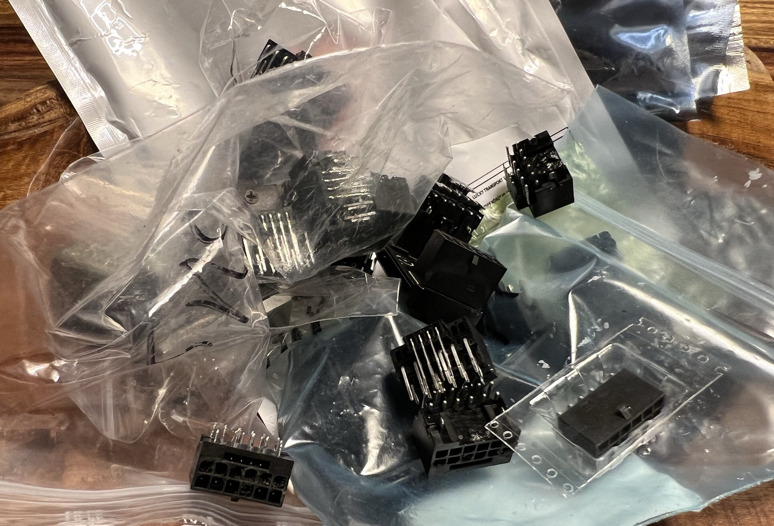 This concerns both the material, i.e., the appropriate alloy instead of pure copper, as well as the definition of the galvanization layer thicknesses, the processing of the wire pieces (cutting, bending), and their positioning (pressing) in the housing. In addition, I miss a strict specification for the minimum contact area and spring pressure on the spring contacts. All these are important factors that are primarily essential for the right connection and should not be left to chance or to the individual manufacturers (which amounts to the same thing).
| Cause of error | Consequence or solution | Cause |
| Insufficient insertion of the cable plugs | Solved via pin lengths (sense pins, power pins), 12V-2×6 instead of 12VHPWR | User |
| Insufficient locking of the cable plugs | Solved via the specification | User |
| Incorrect insertion of the cable plugs | Can bend the header pins (especially the outer ones) | User |
| Pulling off the cable plugs (lateral movement when loosening) | Can bend the header pins (especially the outer ones) | User |
| Excessive bending of the cables | Can bend the header pins (all) | User |
| Pins in the header too narrow | Insufficient clamping surface | Manufacturer |
| Twisted pins in the header | Insufficient clamping surface | Manufacturer |
| Position tolerance of the pins | Less clamping surface, contact problems | Manufacturer |
| Square wire of the pins rounded | Less clamping surface, contact problems | Manufacturer |
| Copper pins | Non-compliance with PCI SIG specifications | Manufacturer |
| Excessively high preheating of the pins on the PCB | Lower temperature window up to 105 °C | AIC |
| Inverse header | 12V pins too close to the hotspots of the PCB | AIC |
Not much more can be investigated or written about connectors, as I took the liberty to tackle the last remaining puzzle piece. The number of tested headers and the consistent damage patterns are surely a statistically secured evidence that the connectors can and must be improved.
Conclusion
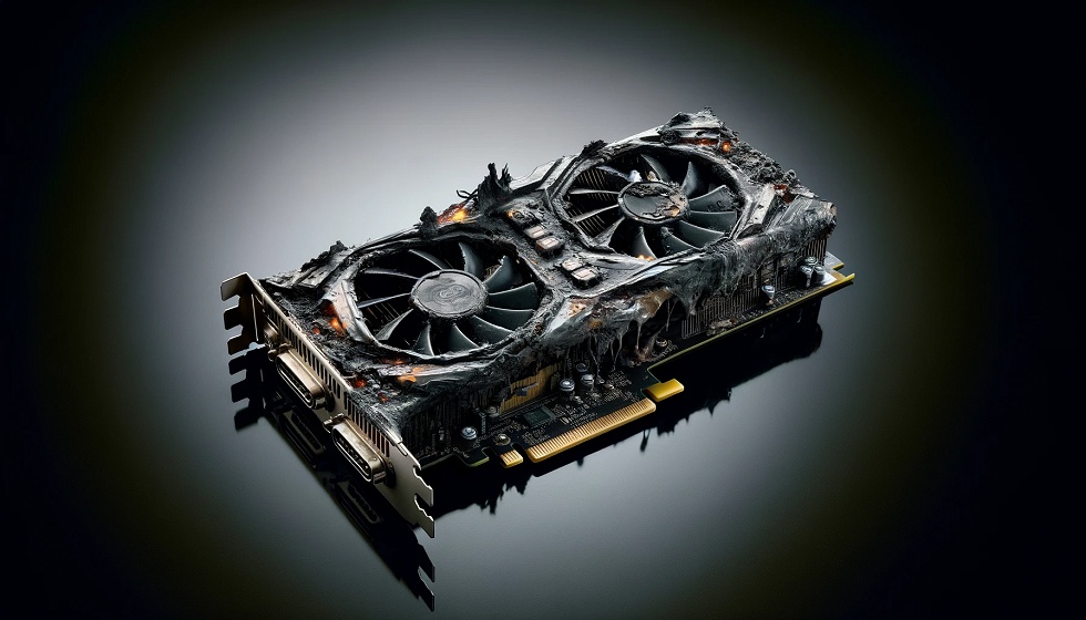
This connector, whether it’s 12VHPWR or the more recent 12V-2×6, remains a rather fragile entity, even though it has been possible to reduce potential defects with precaution and reworking the standards. Because one factor will always have to be included: quality defects from the manufacturers of the connectors. Additionally, negative influences from the circuit board layout of the graphics cards are present, where the pins are often unnecessarily heated by the board. Here, the graphics card manufacturers have a duty to increase the distance of the pins from the hotspots on the board or to cool them.
My thanks go explicitly to KrisFix, who has supplied me with many defective connectors, as well as to the users who sent me their cards for examination. Moreover, CableMod has contributed significantly to the gain of knowledge, as the countless test samples that I was able to examine here have also led me to the result. Taking into account all these findings here in the lab, it is interesting to see that the new adapters now have no higher failure rate after over 8,000 units sold than the normal, native cables from the power supply manufacturers. I patiently waited for this point before writing this article. And yes, I am indeed pathologically curious when something triggers me.
I am done with this connector for the time being, as there will hardly be anything else to investigate or optimize. And I honestly admit: I still don’t quite like this part because it operates far too close to physical limits, making it extremely susceptible to possible influences, no matter how minor they may seem. It is and remains a tightrope walk, right at the edge of what is physically justifiable and without any real reserves. If the quality control also fails in parts, then that’s it for the connector. You just don’t build something like that. At least not like this.

- 1 - Introduction, Important Preface, and the PCI SIG
- 2 - Material Analysis with a Key Finding
- 3 - Damage Level 1: Barely Visible or Minor Damage
- 4 - Damage Level 2: Moderate to Major Damage
- 5 - Pin Width, Twisting, Positional Tolerance, and Clamping Surface
- 6 - Summary, Overview of Most Causes, and Conclusion


408 Antworten
Kommentar
Lade neue Kommentare
Urgestein
Urgestein
Urgestein
1
Urgestein
Veteran
Urgestein
Mitglied
Urgestein
Veteran
1
1
Mitglied
Urgestein
Veteran
Veteran
Veteran
Urgestein
Urgestein
Alle Kommentare lesen unter igor´sLAB Community →