


Some things are accidental discoveries and are actually so trivial that nobody even bothers to question the current flows in the PC and, above all, to measure them. We only ever measure the 12-volt rails and are happy. But with connectors such as the 12VHPWR or 12V2x6 over 6+2 pin, the 8-pin EPS and the 24-pin mainboard connection, does exactly the same current flow back to ground as flows in? Not at all, and that’s what really got me triggered!
I was actually looking for the reason why the 12VHPWR connectors only ever burn the 12V pins and, on the other hand, the ground pins of an 8-pin EPS get extremely hot, especially when using powerful (and extremely hungry) graphics cards. I was also working on a completely different article at the same time, which dealt with audible ground loops in PC audio and their elimination, and was somewhat surprised that all the causes could be reduced to a common denominator!
Important preliminary remark
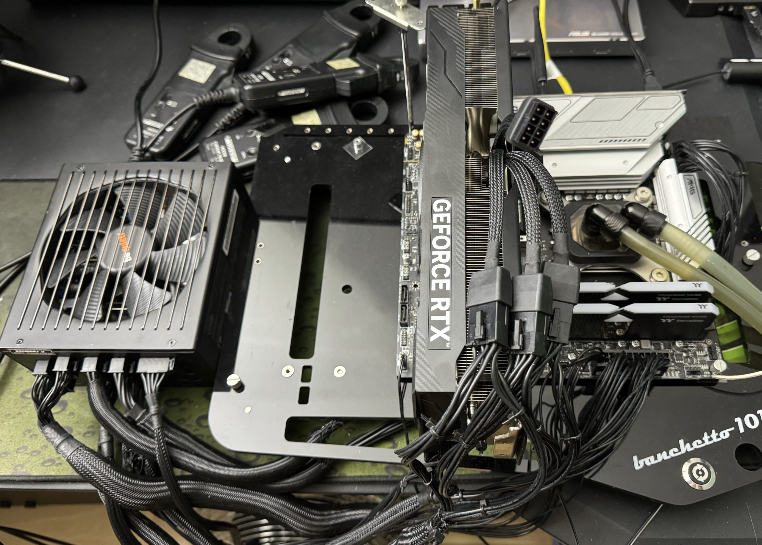
“Ground loops” are nothing new, because electricity is like water and always looks for the easiest and shortest path, even when it flows back. You would never expect to find them where they actually occur. Since the PC case, the type of spacers to the mainboard, the cabling and the power supply unit mounting or the power supply unit itself also play a very important role and there are therefore countless factors and variations, I have very consciously and deliberately mounted today’s experiment on an electrically insulating benchtable. All input and output lines are therefore very easy to compare and measure individually, as there are no additional influences from other earth connections in the housing.
However, you can also test it in the housing and notice that the main points of my current findings and their consequences are still very similar. It is just more difficult to reproduce and generalize. Furthermore, there are of course also different mainboards with very different circuitry, track quality and more or less layers. This and significantly fluctuating temperatures when warming up the boards and graphics cards can of course significantly change the absolute values, but here too it is true that in principle it remains equally unpleasant with the in and out. In order to understand the current, I would like to start with a short anecdote that explains Kirchhoff’s law.
What Mr. Kirchhoff has to do with it
One gloriously sunny afternoon, a certain Mr. Kirchhoff, known for his serious expression and even more serious moustache, decided to take an unusually spontaneous walk along the nearby river. And as he strolled along the bank, with the sun at his back and the gentle lapping of the water as his only company, he began to think about currents. Not about electric currents, oh no, but about the water that flowed so happily past him. In a moment of exhilaration (or was it the heat going to his head?), he began to think of the water and the leaves floating by as electrical charges flowing through an electrical circuit.

“Interesting,” he muttered to himself as he watched a particularly nimble leaf swirl around a rock before continuing on its way. “If I’m seeing this correctly, the river behaves very much like an electrical circuit. The total amount of water, whether before or after the watermill or the parallel weir, that enters here must be exactly the same as the amount that comes out much further back. An eternal balance! I think I’ve just discovered a fundamental principle of electricity – on the banks of a river, mind you!” A law that from then on would not only strike fear into the world of electricity, but also into the hearts of physics students worldwide. And if you listen carefully, you can still hear the quiet giggling of the ducks who were the first to witness how a flowing stream provided the inspiration for one of the fundamental laws of electrophysics.
These Kirchhoff’s laws, also known as Kirchhoff’s rules, refer to two fundamental rules in electrical engineering that are used to analyze currents and voltages in electrical networks. These laws are crucial for understanding and analyzing electrical circuits. There are two main laws, the first of which is of most interest to us today.
-
Kirchhoff’s current theorem (node point theorem or first Kirchhoff’s rule)
This law states that in every node of an electrical network (a point where conductors come together), the sum of all currents flowing in is equal to the sum of all currents flowing out. This law is based on the principle of conservation of charge, according to which electrical charge can neither be generated nor destroyed. Electricity can therefore not be consumed. -
Kirchhoff’s voltage law (mesh law or second Kirchhoff’s rule)
This law states that in every closed loop of a network, the sum of all voltage drops (caused by components such as resistors) and the voltages generated by sources must be zero. This means that the algebraic sum of the products of current and resistance plus the sum of the electromotive forces (EMF) in the loop is equal to zero This law follows from the principle of energy conservation in a closed loop.
These two laws are fundamental for circuit analysis, as they make it possible to calculate unknown currents and voltages in complex networks by setting up a system of linear equations that can be solved using linear algebra methods. But we don’t have to make it quite so complicated today, although of course, as always, what you put in must come out. And so we expect that everything that is supplied to the PC on the 12-volt rail also comes back to earth. And it does, but it’s better to measure where and how it all comes back.


184 Antworten
Kommentar
Lade neue Kommentare
Neuling
Veteran
Urgestein
1
Urgestein
1
Mitglied
Urgestein
Veteran
Urgestein
Urgestein
1
Urgestein
Urgestein
Veteran
Urgestein
Mitglied
Urgestein
Urgestein
Alle Kommentare lesen unter igor´sLAB Community →