


I won’t repeat all the speculations, attempts, and potential explanations, as they’re now just tiresome. However, what has persisted is the rather one-sided blame placed on users for allegedly being too clumsy to plug in correctly. Yes, there were such cases, especially when the cables or adapters were difficult to insert and users, out of fear, refrained from using force. But we must acknowledge that this was just one of many reasons. Nonetheless, the PCI SIG decided not only to criticize the original spring contacts (which I also reported exclusively) but also to ensure user safety, something overlooked in the first model.
The 12VHPWR Connector Goes, and the 12V-2×6 Connector Comes
Taking seriously the findings from the first few months, the connector was modified, a new standard was developed, and extensive testing was conducted (which should have been done at the start). The product was renamed, although it was essentially an evolution. Looking at the newly introduced implementation guidelines, it’s clear that my articles and videos about cable bending, crimping, soldering, and lateral stress were spot on. Blaming the 12VHPWR issues solely on user incompetence may have been convenient for NVIDIA just before announcing quarterly results, but it oversimplifies the complex matter.
The new CEM 5.1 specification replaced the 12VHPWR plug with a new 12V-2×6 plug, aiming for less confusion by defining the rules for maximum and sustained power in the same way as commonly used form factor specifications. This plug design was introduced to support cards up to 675 watts, with up to 600 watts for the plug and up to 75 watts for the motherboard slot (PEG). This was a novelty, as previously, the CEM 5.0 set a maximum power of 600 watts for the combined connections, irrespective of their distribution.
Additionally, the standard method for measuring maximum and sustained power was finally updated to align with existing form factor specifications and ensure consistency between them. There were no impacts on hardware not supporting 12V-2×6, but minor effects on hardware that had to follow the base specification for implementing the 150W and 300W versions of the 12VHPWR sense-pin detection.
There were also no software implications unless the software supports the CEM form factor. Software using the Power Budgeting Sense Detect Register will need updates to reflect the new defined codings. Software utilizing the “Connector Type” field must be updated to support additional connector type coding. However, so far, there’s nothing significant known in graphics cards and power supplies – it was never implemented anywhere. Configuration storage tests might need updates to avoid mistakenly marking expansion cards using the new codings as defective.
The new 12V-2×6 power connector also delivers up to 55 A of continuous current, supplying the expansion card with a maximum of 600 W at a 12 V Aux rail. The power requirements for the plug and cable assembly are as follows:
- Current rating of power pins (excluding sideband contacts): At least 9.2 A per pin/position with a limit of 30 °C T-rise above ambient temperature conditions at 12 V DC with all twelve contacts active.
- The plug body must have a label or an embossed H sign to indicate support of 9.2 A/pin or more. See the above figure for the approximate positioning of the marking on the 12V-2×6 Right-Angle (R/A) Header.
- Due to variations in contact resistance, a single pin might see more than 9.2 A, depending on uneven cable contact resistance, but the total current for the assembly must not exceed 55A RMS in any direction. This also affects measurements and requirements for contact resistance variability.
- Cable assembly integrators must ensure that the assembly, including the 16 AWG wires and pins, meets the minimum current requirement and maximum temperature rise as stated above for their implementation.
- Holding force of the locked plug: At least 45.00 N when the plug is axially pulled.
Mechanical Changes to the Header
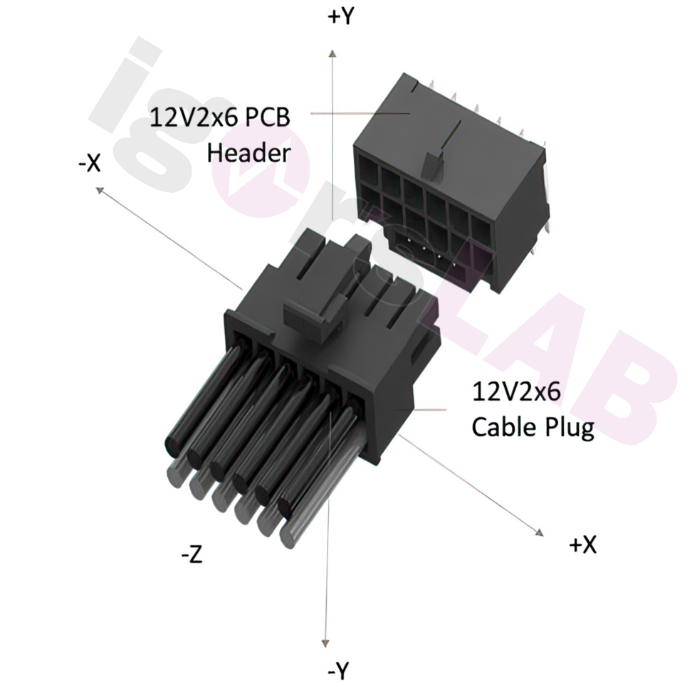
The so-called header, the socket soldered to expansion cards like graphics cards, saw the biggest change. The 12V-2×6 plug is now conditionally compatible with older graphics cards with 12VHPWR headers, and current 12VHPWR power supply cables and adapters will be more or less compatible with the 12V-2×6 header. Twelve large contacts carry the power rail as before, and four smaller contacts below carry sideband signals. This is where the most significant changes occurred.
The update of the 12VHPWR coding was also done to reflect the now-published CEM 5.1 (as the base specification and CEM 5.0 were even inconsistent). New rules applied to expansion cards with 150 watts or 300 watts, and detecting 150-watt cards even required external circuitry (see below). Logically, the 12V-2×6 is still not compatible with PCI Express 2×3 and 2×4 PCIe plugs (Aux). The power pins of the 12V-2×6 plug have a spacing of 3.0 mm, while contacts in a 2×3 and 2×4 plug are on a larger grid of 4.2 mm.
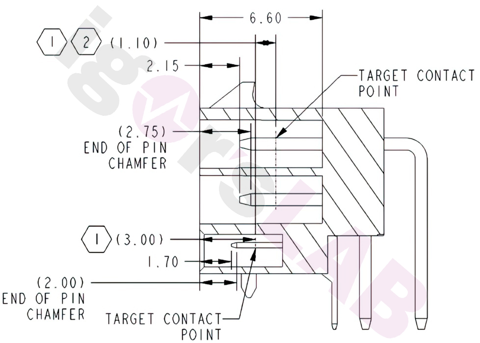
I wrote over a year ago that the PCI SIG would mechanically reset the four lower sideband signal sense pins. Unless the plug is inserted far enough into the header (until it clicks), the sideband signal of the two pins for detection is missing. This prevents the card from powering on or immediately shuts it off if the plug accidentally slips out. The 12V-2×6 header has the same external dimensions, and the final pressure point of the sense pins is again at 3 mm to ensure compatibility. But here’s the interesting part: the tips of the sense pins are now recessed by 1.7 mm, a change of 1.25 mm. The actual pin behind the tip, where the first contact is made, is now even 2 mm behind the outer edge. This greatly increases safety.
New Power Classes with 150 and 300 Watts
By connecting Pin 0 to ground and leaving Pin 1 open, 300 watts is achieved. The 150-watt configuration is tricky and new: Pin 0 and Pin 1 are simply connected directly without ground. This requires new cables or a special power supply:

Mechanical Changes to Connectors with 2 Options
The connectors for cables or adapters will also be slightly modified, and there will likely be two slightly different versions. Option 1 has a 0.7 mm step below the sense pins, while Option 2 doesn’t. However, the external dimensions of both options are identical. The reason for these options is not yet clear.
 The same applies to spring contacts, even though the PCI SIG’s last recommendation in CEM 5.0 clearly spoke against Astron contacts. The NTK design was explicitly recommended.
Important Implementation Notes for 12V-2×6 Cables Regarding Quality and Processing
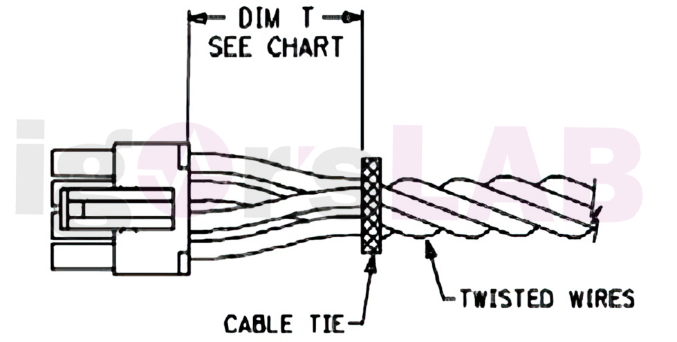
To avoid unnecessary stress on the crimp contacts, the cable bundles should not be bent immediately after exiting the back of the plug. The cables should neither be stretched nor restricted in any way. The IPC/WHMA-A-620 standard prescribes practices and requirements for the manufacture of cable, wire, and cable assembly. The standard describes materials, methods, testing, and acceptance criteria for the production of crimped, mechanically secured, and soldered connections, and the associated assembly activities (appropriate fastening/restraint criteria) in relation to cable and cable assembly.
Variability in contact resistance within a cable assembly can cause an imbalance of current between contacts, potentially causing individual contacts and/or wires to exceed the current per pin specified in Section 9.1. Furthermore, this imbalance can be exacerbated by cable bending and/or lateral loading of the cable assembly connected to the expansion card. The specific wire, connectors, and manufacturing process used for a cable assembly must be designed to accept this current imbalance due to contact resistance variability and side loading. Side loading is defined as a load applied in any direction perpendicular to the housing bodies as defined in Figure 9-10.
I recall in this context that I addressed exactly these side-loading circumstances in both my previous investigations and in articles and videos. The inclusion of this important aspect in the specifications after many hints and measurements confirms once more that pure generalization of user error simply cannot do justice to the problem. This also pertains to my investigations into crimping, soldering, and cable execution.
Measurements and Testing Procedures
For better understanding, let me briefly explain Low Level Contact Resistance (LLCR). LLCR is used in combination with several other tests to track the overall performance of a component under specific conditions. The goal is to measure the electrical resistance of a system under test at a no-load voltage. This voltage is low enough not to disturb any thin films that might exist at the contact point.
The current level is also low enough to ensure that the device under test does not heat up and that surface irregularities (asperities) do not melt. In other words, the current is low enough to prevent the destruction of oxide layers and thus avoid falsifying the results. LLCR is measured in milliohms (mΩ), and a normal LLCR reading for a board-to-board system is between 5-15 mΩ. For testing, the voltage is limited to 20 mV and the current to 100 mA. A change in resistance greater than 15 mOhm is typically considered a failure.
To measure low-level contact resistance and check if a coupled connector head and cable assembly design can control contact resistance under side load conditions, the following methodology is proposed:
- Attach the connector of the expansion card to a fixture.
- Measure the LLCR of the cable assembly from the socket’s footprint on the top of the expansion card’s PCB to 50 mm from the point where the wire leaves the body of the connector. The purpose of controlling the measurement point is to ensure that the wire length and its contribution to contact resistance are repeatable. This does not imply a limitation on the specific cable assembly implementation.
- Perform 30 mating cycles between the connector and the cable assembly.
- Record the LLCR of each conductor of the cable assembly in the unloaded state.
- Apply a side load of 20 N in each of the directions defined above. The load must be applied to the cable bundle beyond any cable ties or strain relief features of the assembly, if present. Record the LLCR of each conductor once the measurement result has stabilized.
- Calculate the average contact resistance of pin groups 1-6 and 7-12 independently for each side load condition.
- The LLCR result for each pin should not change by more than 50% from the average of its respective group under any test condition. A maximum LLCR of 6 mOhm/contact is prescribed for each conductor.
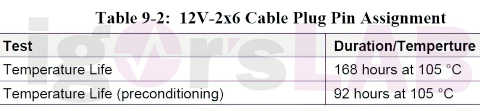
Temperatures
New specifications regarding temperatures and limits have also been released. Considering the heat development of the board (shunts exceeding 100 °C!) and the potential heating of the pins due to external influences from the board, not just from the flowing currents and contact resistance, one can conclude from the established temperature limits for durability that air-cooled cards, especially in the area of the power connection, should be designed differently.
- 1 - 2x EPS and over 700 watts? It could have been so easy!
- 2 - NVIDIA runs out of space with the Founders Edition
- 3 - GeForce RTX 3090 Ti: Playground for Ada and the 12VHPWR
- 4 - NVIDIA's mystic 12VHPWR adapter
- 5 - From 12VHPWR to 12V2x6 connector - user error de luxe?
- 6 - Flip headers, quality issues and a conclusion


37 Antworten
Kommentar
Lade neue Kommentare
Urgestein
Urgestein
1
Urgestein
Mitglied
Urgestein
1
Urgestein
Urgestein
1
Veteran
Veteran
Urgestein
Urgestein
Urgestein
Urgestein
Neuling
1
Alle Kommentare lesen unter igor´sLAB Community →