


Teardown: PCB layout and components
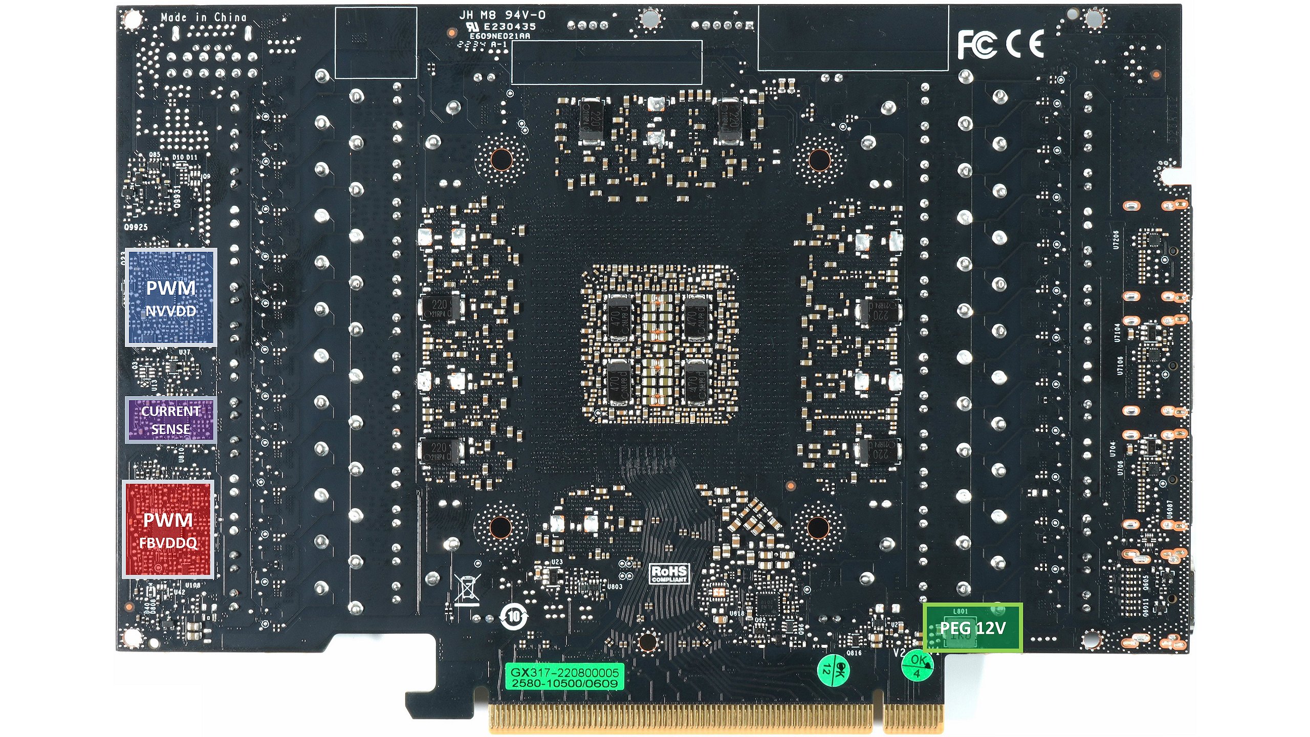
I have already discussed the changes in the load change behavior and the power consumption, but more about that later in this review. First, let’s start with the board itself. NVVDD is still the main voltage and MSVDD has been buried for good. This also results in the voltage transformer design with a total of 9 phases and the resulting 18 control loops for NVVDD alone (two in parallel per phase). The GeForce RTX 3090 Ti still relied on 8 phases and a total of 24 voltage converters, so three per phase in parallel, and the RTX 4090 Founders Edition on 10 phases and 20 voltage converters. And then comes KFA2 with 9 and a new, still undocumented PWM controller.
The gaps on the PCB show 4 unused control prices, so now you know why you chose the limit with the 450 watts. That you rely on a solid parallel circuit instead of phase doubling makes perfect sense, because with the now also higher switching frequencies, double the number of phases would only be a hindrance due to the inertia of the coils and caps. Cheaper cards still rely on doubled 8-phases, because the PWM controllers and also the DrMOS cost hard cash. KFA2 thus makes a certain compromise here, which at least offers one more real phase and two more control circuits than the currently cheapest model in the form of the Palit RTX 4090 GameRock.

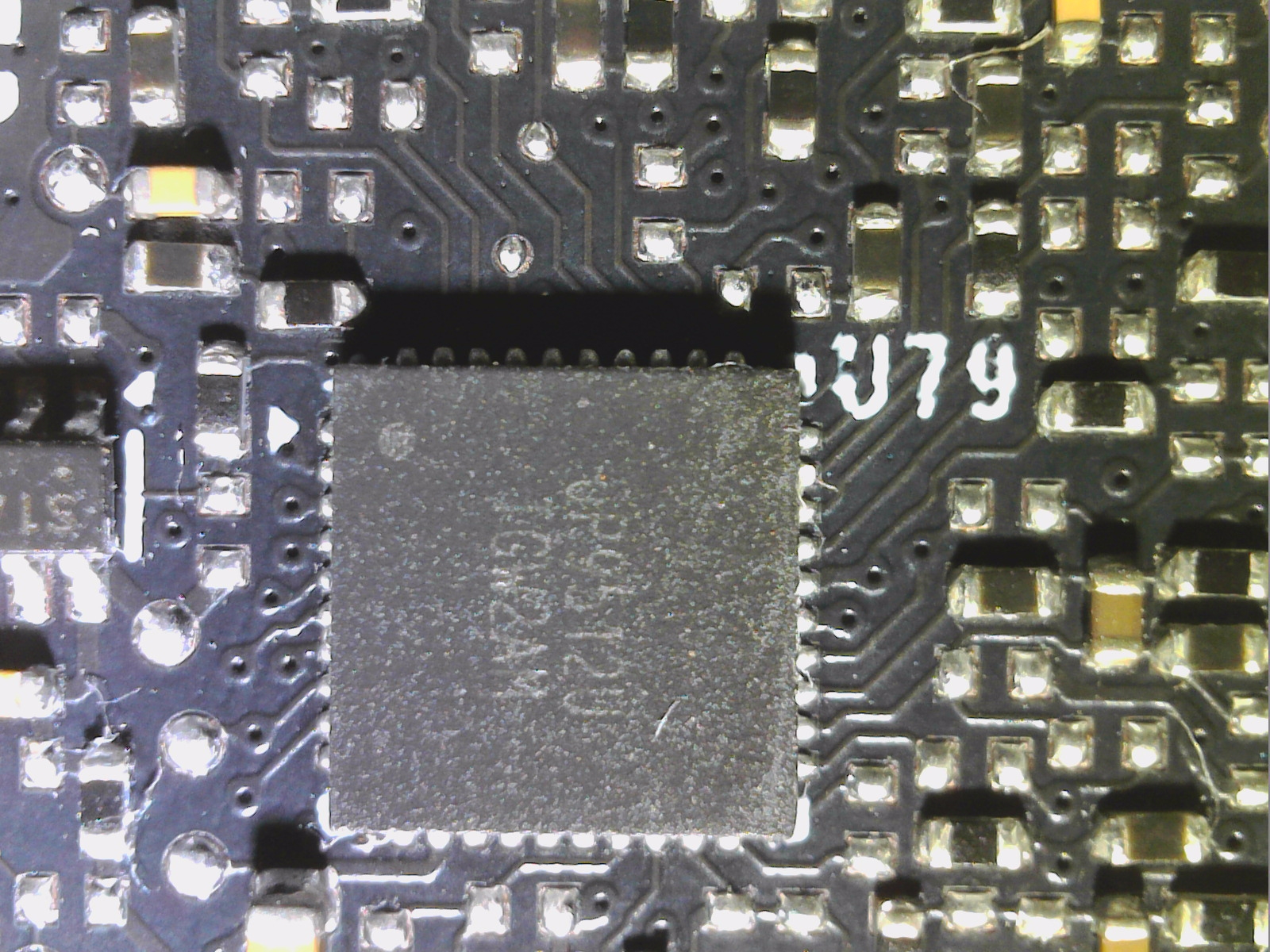
The PWM controller for NVVDD (GPU core) in the form of UPI’s uP9512U is currently the latest iteration of the 9512 series of PWM controllers from this manufacturer. It is a digital controller that primarily provides power to the NVIDIA PWM VID core and is also compatible with the AVSBus interface. It can (and should) also work with MPS’s Intelli-PhaseTM products to complete the multi-phase voltage regulator (VR) solution with a minimum of external components.
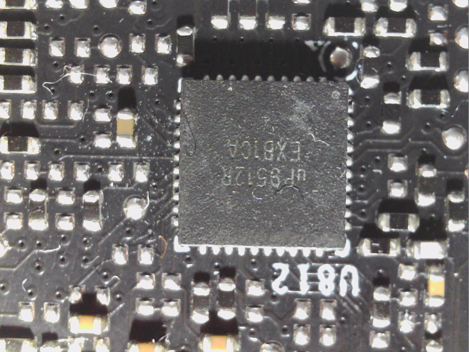
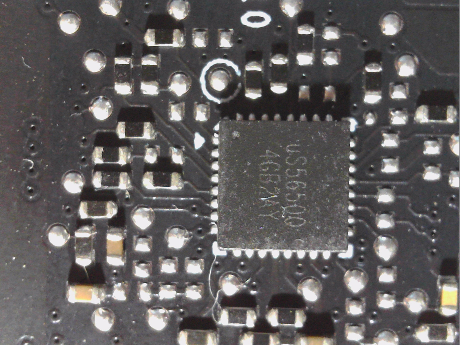
A uP9512R then drives the four FBVDDQ phases for the memory (the FE uses three). Like the uP9512U for NVVDD, it is located on the back of the board. Right next to it is a uPI uS5650Q for monitoring the four 12V rails (3x Aux and 1x PEG).
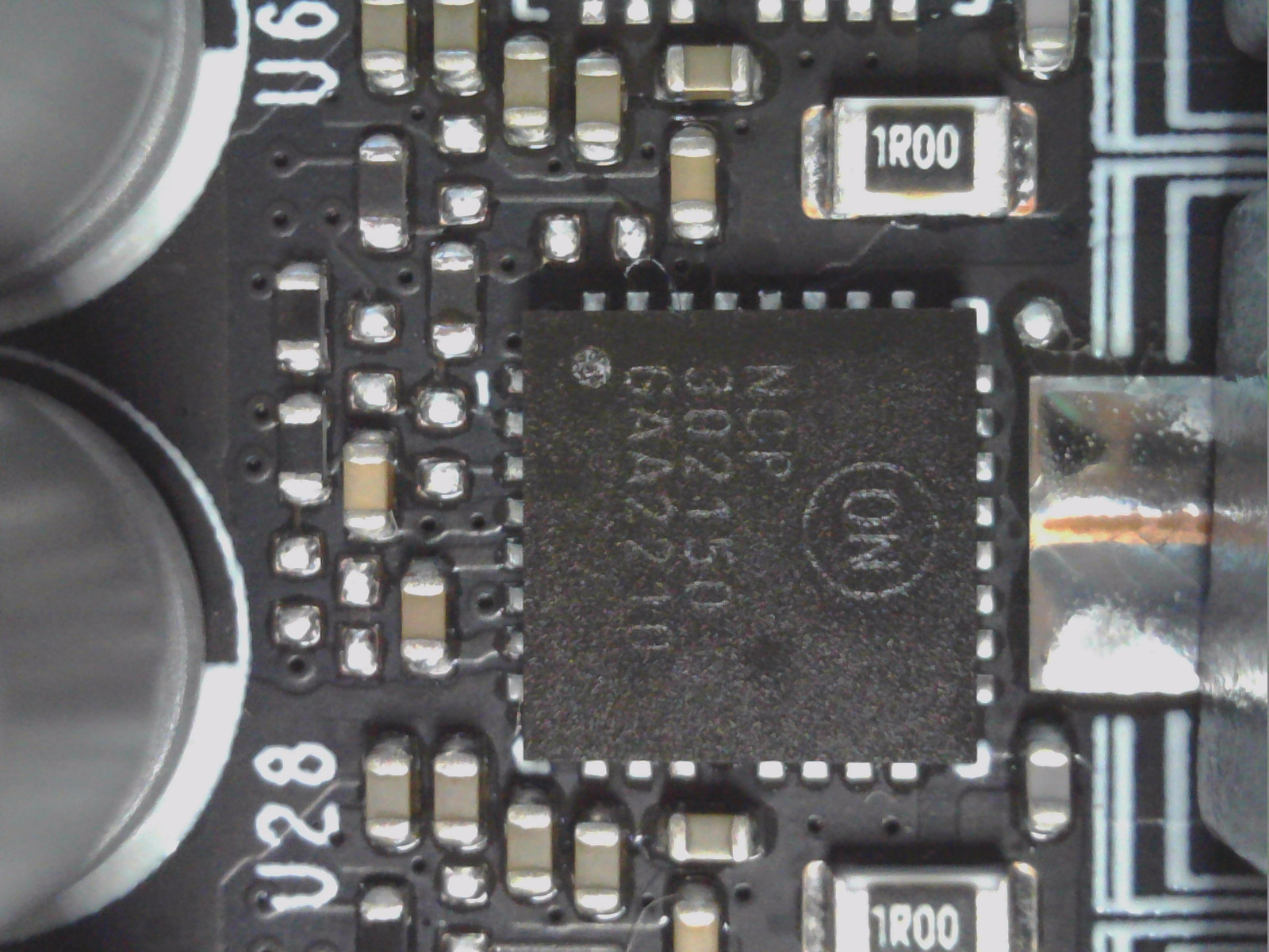
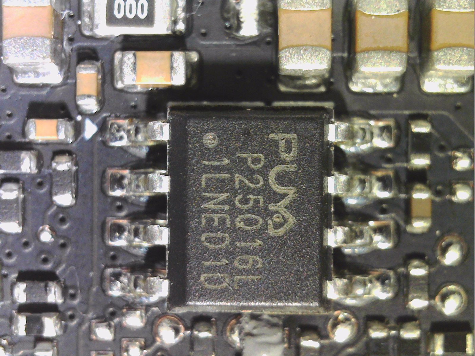
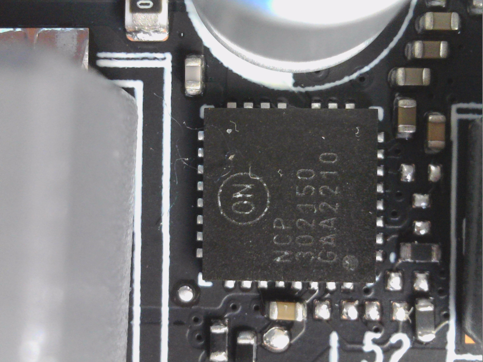
All of the power stages used, including those for the memory, are mid-priced products from OnSemi in the form of the NCP302150. The chip implements a monolithic half-bridge capable of driving up to 50A per phase. The integration of drivers and MOSFETs (DrMOS) results in high efficiency due to optimal dead time and reduction of parasitic inductance. This small, 5 mm x 6 mm LGA device can operate at frequencies from 100 kHz to 3 MHz and is, of course, not high-end.
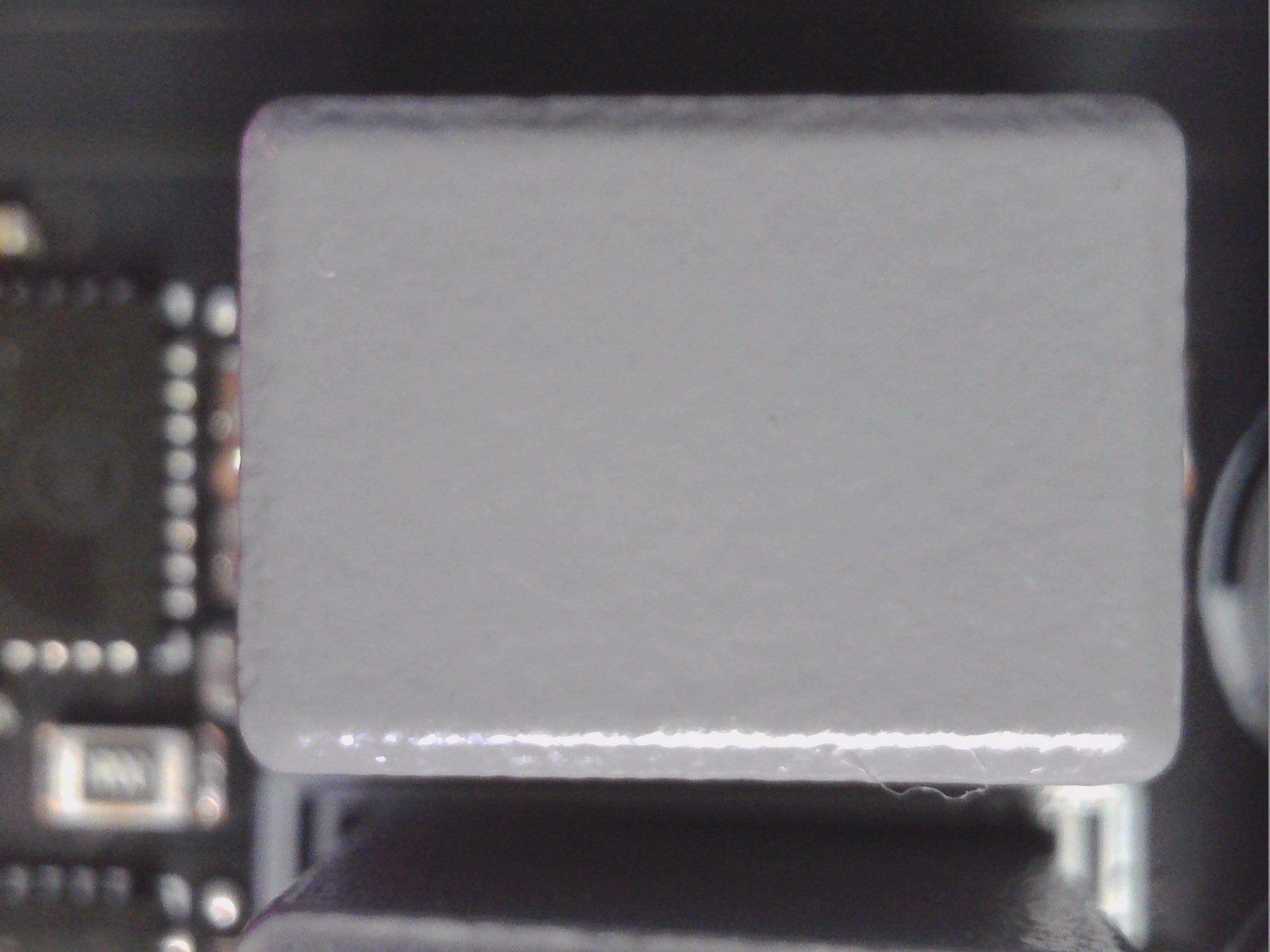
The completely unlabeled coils used for NVVDD have an inductance of 120 mH, those for the memory one of 150 mH. KFA2 has obviously made an effort to improve the quality a bit, but it is still never possible to do it without any noise, unfortunately. Rather negatively, you have to actively cool the coils’ approximately 0.5 watts of power dissipation, because the cooler coils are, the louder they unfortunately become (note the expansion coefficient). This is also usually stated in the specs as the optimal temperature window. I would have left it out.
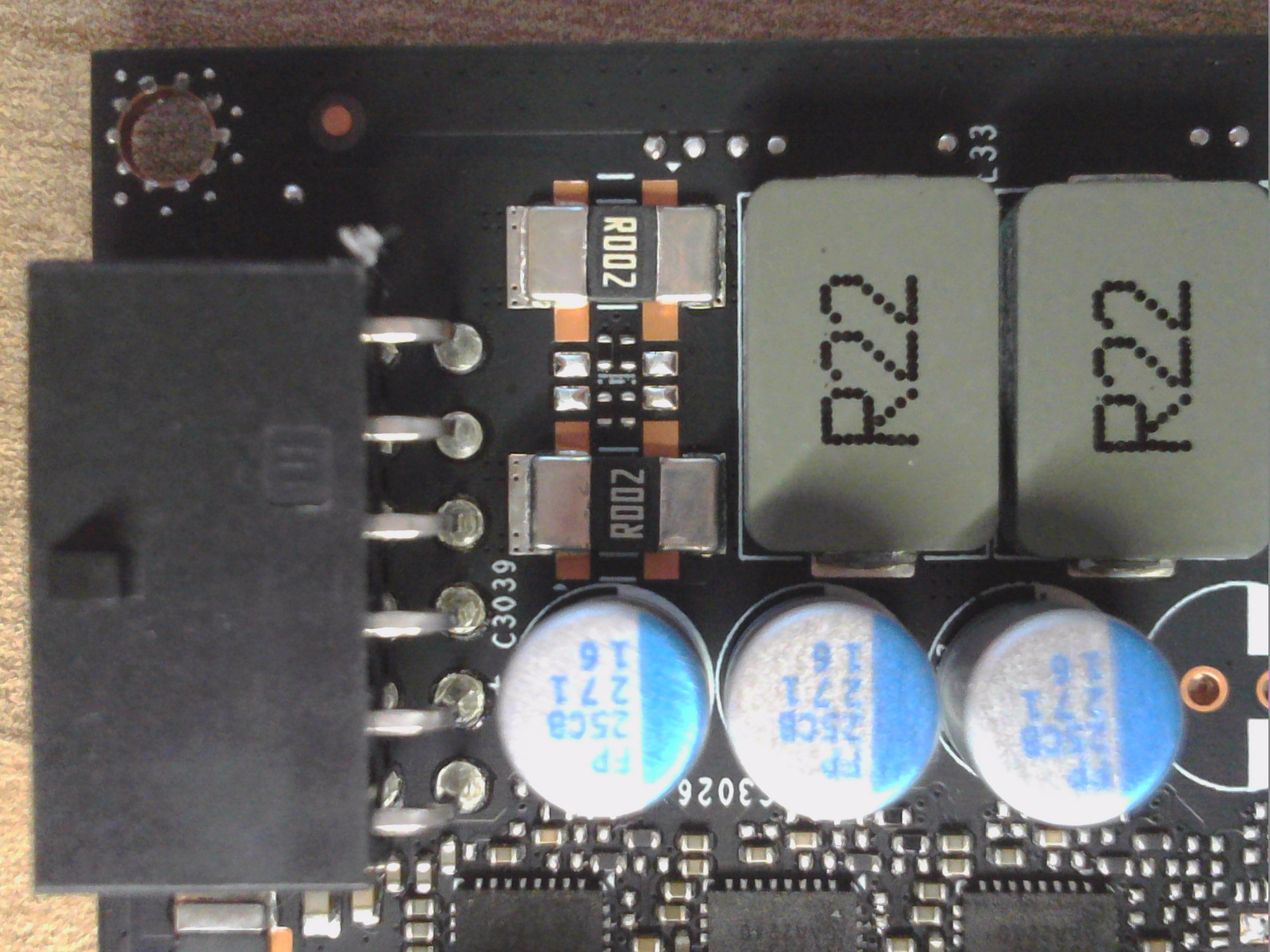
The two 12V rails on the 12+4 12VHPWR connector are combined into one rail after the two shunts (one per rail), another one is connected to the PEG but is not used for NVVDD. The single BIOS is at the usual place and also the generation of the remaining extra-low voltages is as usual. So there are no more special features.

Teardown: The cooler
The airflow is provided by three 9.5 cm fans (10 cm opening) on the front with 11 strikingly shaped rotor blades each, which should also provide a bit more static pressure in the thick cooler. We will see later that this principle can work.

The actual heatsink cools the GPU and the RAM modules, the rest is done via the thermally attached support structure or the flattened six heatpipes, which also cools the voltage converters.
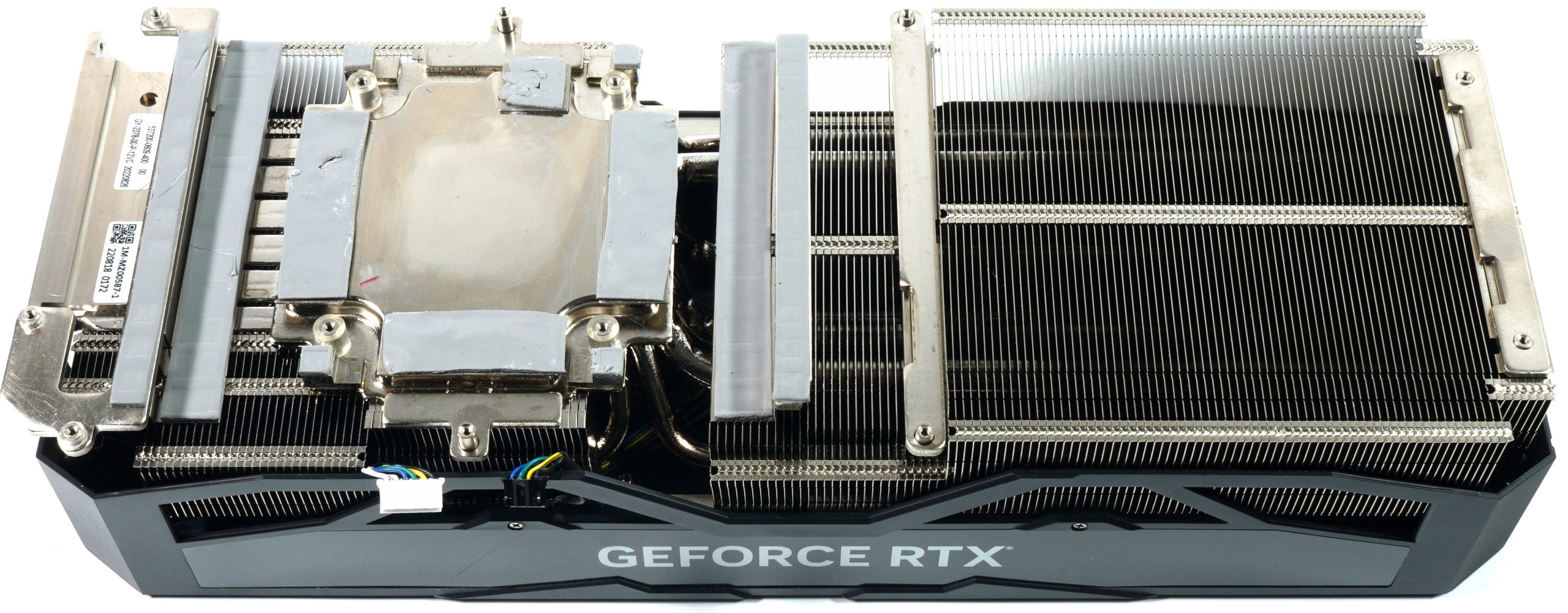
The pads used are practical, well malleable and yet somewhat brittle. Advantage: nothing oils out anymore. Since they adhere very well, disassembling the card is not without its problems, as the pads are damaged for the most part and have to be completely replaced when reassembling. Very good, reasonably soft pads with a thickness of 1.5 to 1.75 mm should be used here.

- 1 - Introduction, technical data and technology
- 2 - Test System and the igor'sLAB MIFCOM-PC
- 3 - Teardown: PCB and cooler
- 4 - Gaming Performance
- 5 - Power Consumption and load balancing
- 6 - Transients and PSU recommendation
- 7 - Temperatures, clock rates, fans and noise
- 8 - Efficiency. summary and conclusion


109 Antworten
Kommentar
Lade neue Kommentare
Urgestein
1
Veteran
Veteran
Urgestein
Veteran
Veteran
Urgestein
Urgestein
Urgestein
Urgestein
1
Neuling
Urgestein
1
Urgestein
Urgestein
Urgestein
Urgestein
Alle Kommentare lesen unter igor´sLAB Community →