Basics GPUs Graphics Practice Reviews

Power Supply in Graphics Cards explained – Switching Voltage Regulators, PWM Controler, true Phases and the annoying “Coil Whining” | Reminder

What are phases, anyway?

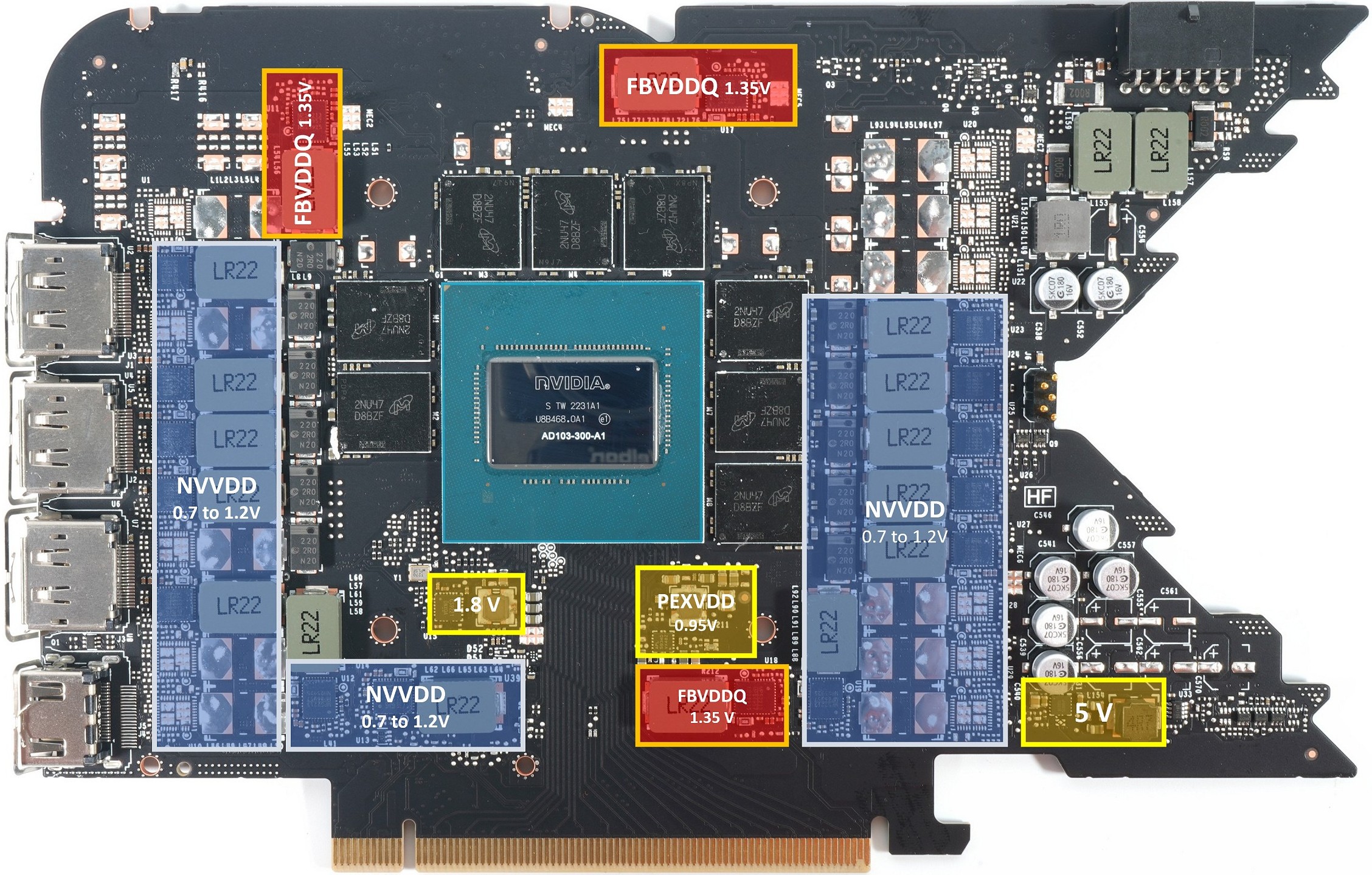
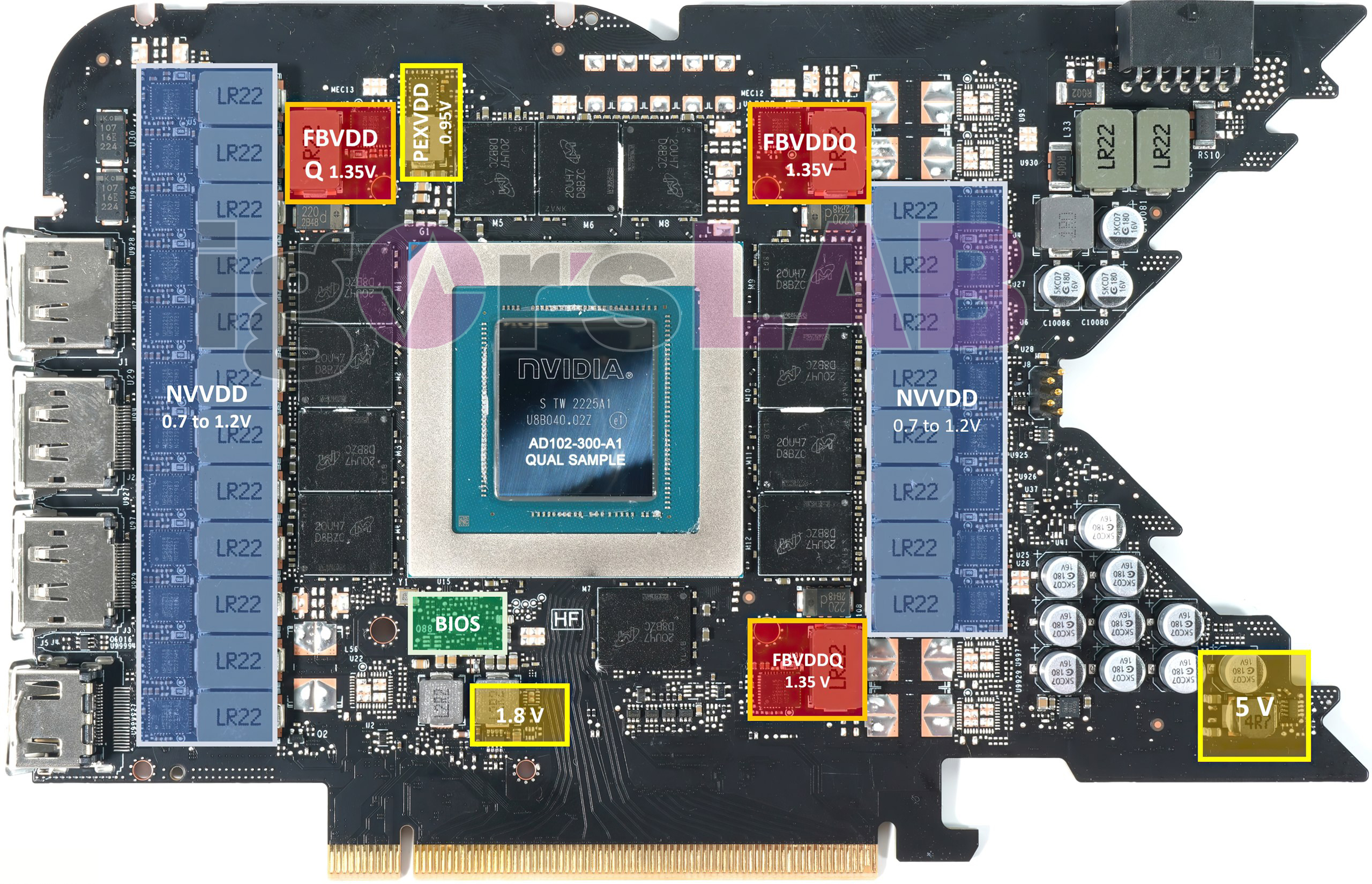
We have already dealt with the individual switching regulators, but in the broadest sense it is only a single phase. Here, however, physics sets very strong limits. If you look at the pictures of the boards of the RTX 4080 FE and RTX 4090 FE, you will also notice that the lowest voltages like 1.8 Volt are generated with a simple buck converter. However, you can neither realize the high currents of a GPU nor achieve a good ripple with a single switching regulator. There must be something else, because the picture alone shows that this can not yet fit so!

The multiphase DC/DC converters we need are a nice teaching example of the so-called equilibrium principle in electronics. So we have to pay a price for a desired advantage in the form of a compensating disadvantage. If we think back, we also know that the ever faster switching speeds to increase the processing power of such a GPU has simultaneously led to the necessary reduction of the typical base supply voltage from initially 5 Volt to 3.3 Volts and now to less than 1 Volt.

In turn, supply currents have risen sharply as circuit complexity has increased. The reason that multi-phase DC/DC converters are used on a graphics card is, of course, also due to the limitations of the output filter components (coils, capacitors). In order to guarantee a low voltage ripple at the output at higher load currents, their values cannot be selected arbitrarily high for both technical and economic reasons. In addition, care must be taken with the space and height. This is only possible with multiphase switching controllers.

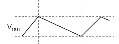
Unfortunately, I can’t spare you a bit of theory here either. So again slowly: During the repetitive charge and discharge cycles (we already know) the output voltage of each switching regulator changes by the peak-to-peak value of the so-called ripple (vripple). However, when the load current increases, the discharge current and the charge current also increase. In plain language, this means that the current flowing through the MOSFETs, the coil and the capacitor is now increasing.

From the first page we know that the ripple voltage must be kept as small as possible by increasing the switching frequency and/or the L and C values. Here, each board partner still has some creative leeway. However, to keep efficiency as high as possible, the MOSFETs, coil and capacitor must have the lowest possible series resistance, which in turn leads to bulkier components. EMC concerns set a limit to the maximum switching frequency (we already know that, too). And now? Multiphase converters solve this problem by sharing the load current through multiple components and things get interesting.

Rather cheap PWM controller for up to 8 phases
High-quality PWM controller with up to 16 phases

A disadvantage of the multiphase implementation is the higher cost of the components, since at least two more MOSFETs or a DrMOS/SPS and another inductor are required for each additional phase. Furthermore, the PWM controller must also be able to implement this multiphase control by realizing phase-shifted multiple output signals. Now, however, the inductor and capacitor sizes can be much smaller, requiring much less space. In addition, the maximum amplitude of the combined output voltage is reduced, so the current flows more smoothly. Also electromagnetic interference is reduced and you can even reduce the degree of filtering at the input (example see picture below). In addition, the response time during load changes decreases (very important!) and the adjustment time is reduced.

Input filtering of a GeForce RTX 4080

The difference between phase and voltage regulator

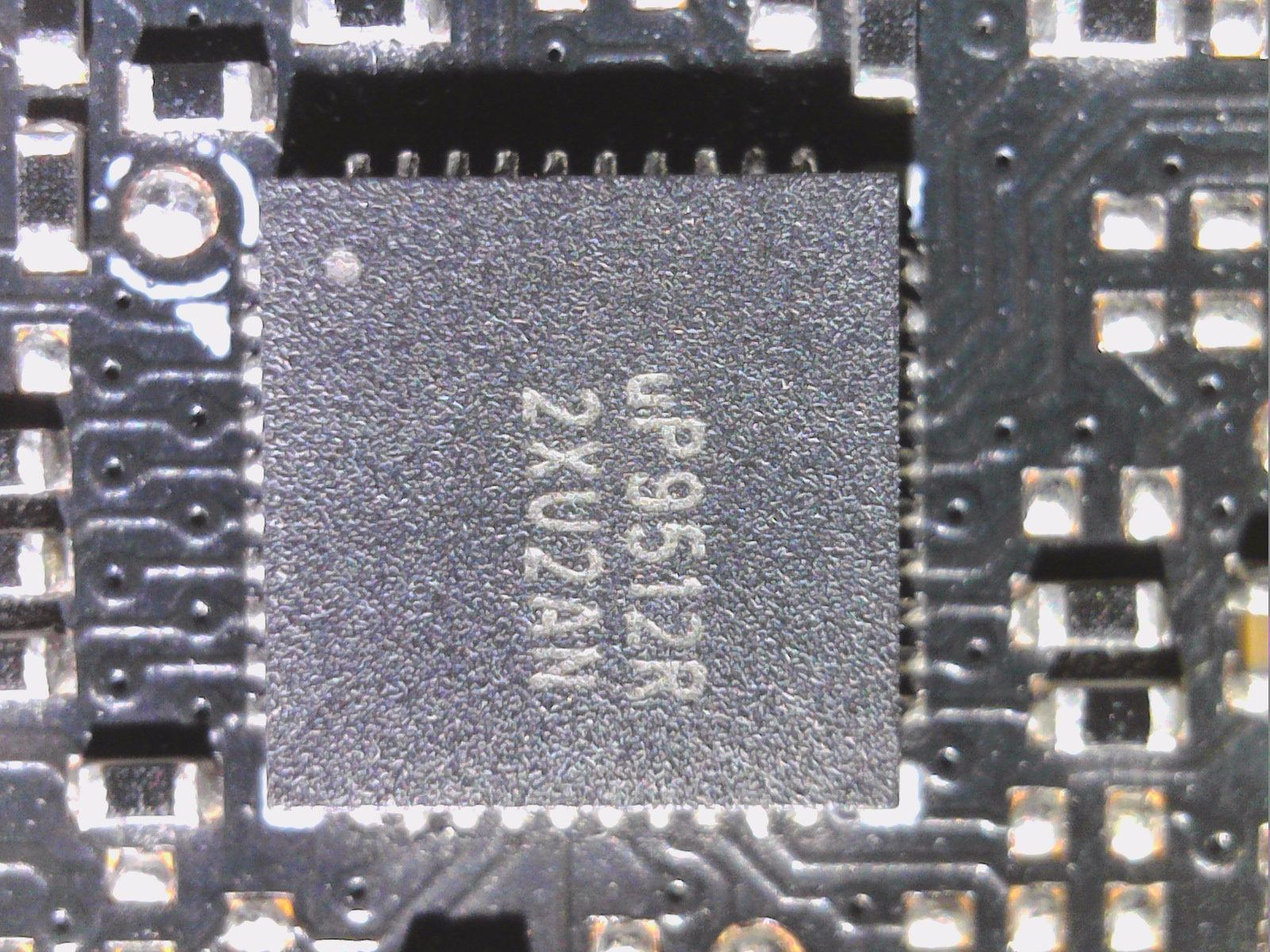
In the minimum case, there is exactly one single voltage regulator per phase. In the picture we now see the GeForce RTX 4080 FE, which uses a good PWM controller (MP2891 from Monolith, picture further up on the right) to generate 13 real phases for the GPU (NVVDD, blue) and thus drives a voltage regulator with a DrMOS in each case. Extra gate drivers are not needed, resulting in a very compact board. I see the FE as a good teaching example of how far you can really go with single phases without it becoming too expensive and time-consuming.  Here, the number of phases still matches the countable voltage regulators 1:1.

The next example is the NVIDIA GeForce RTX 4090 FE. Here we count 20 switching regulators for the GPU (NVVDD), but the installed PWM controller could natively only generate a maximum of 16 phases on rail 1. Now a compromise takes effect, which is quite suitable, because also the development of the input EMC filters is easier, if there are not too many phase-shifted input return currents flowing in the circuit. So the card has “only” 10 real phases! However, the built-in PWM controller allows two switching regulators to be operated in parallel on each phase!

This achieves two things: First, the currents per switching regulator of a phase decrease by half and thus also the internal resistance in the sum and second, lower currents flow in the coils and the Lorentz force decreases. Ergo, it becomes quieter and it also buzzes and squeaks significantly less or not at all! The coils of the thirteen individually controlled switching regulators of the RTX 4080 FE are also only rather inconspicuous in total because the card has a lower power consumption than the RTX 4090 FE and lower currents are already in play per se (“energy portions”).

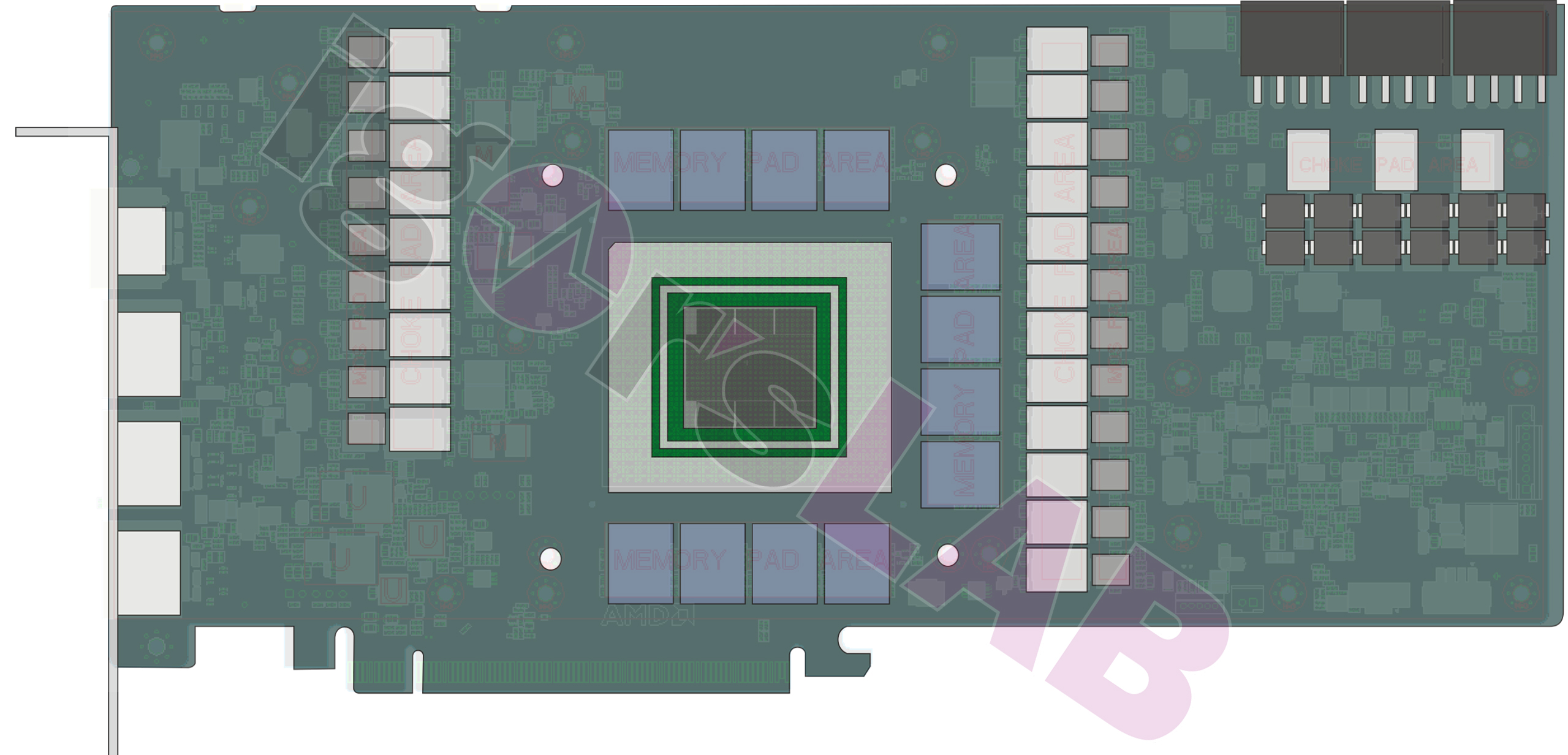
So you can see that the ratio of phases and switching regulators always has a very important background as well. On the last example, we see an AMD board partner card of the RX 7900 XTX and count 21 switching regulators. AMD advertises its own reference card with 20 phases in the slides, but this calculation doesn’t really add up either. But I’d rather wait for the finished product at launch before I go out on a limb and violate any NDAs.

Of course, you can spoil the most beautiful design with extremely lousy coils, but I’ll get to that later. Now I have to take another look at the marketing of some providers.

Marketing chatter vs. reality

Most graphics card manufacturers count the switching regulators all as phases, even if it is against all reason and logic. After all, big numbers sell better. And then you add the smaller items for the memory and, in AMD’s case, VDDCI and SoC as well. Sounds good, but in the end says little or nothing. Because then you could also add the buck converters for 5 volts, 1.8 volts, PEXVDD, and so on. This would then become increasingly pointless.

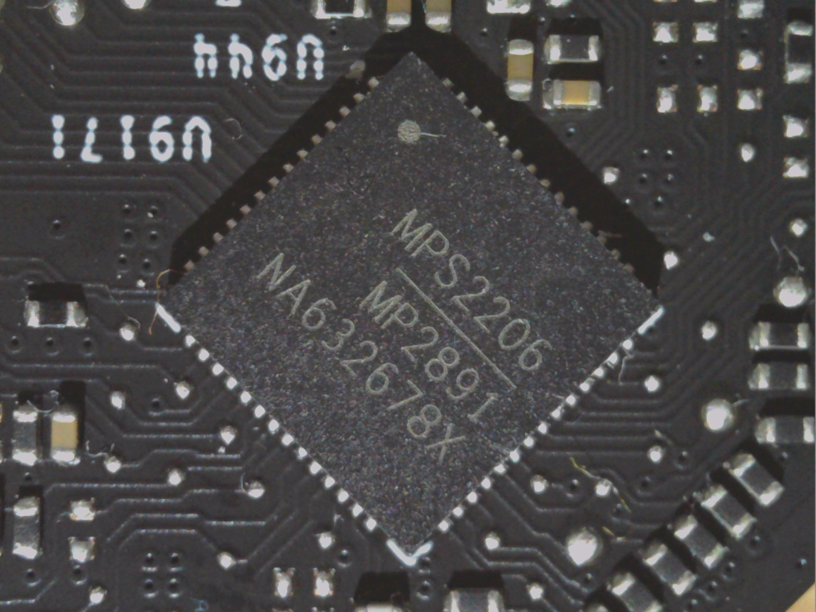
Here I have a nice example of a card from Zotac, which is advertised with 16+4 power phases.  No, the part actually has only 8 + 2 phases, using for NVVDD the uP9512R shown above (the R stands for parallel connection) and the memory relies on a double buck controller with two single phases and parallel connection. There are 16+4 switching regulators, but that sells worse because no one can do anything with it. But now you are smarter and see through the sellers. And let’s put it this way: Even doubled, the danger of getting into the rattling and whining of the coils from 300 watts onwards during fast load changes with only 8 phases is quite real. Doesn’t have to be, but it usually will be.

By the way, this so-called “Power Boost” is nothing more than a group of simple but tricky MLCCs that work de facto as backup capacitors. That’s a good sell, but if you’ve been paying attention, you’ve read the paragraph on sizing smoothing. The better the topology and component selection, the less you’ll have to improve later and the rest is done by the MLCC directly under the GPU socket, which has to be installed anyway.

Special forms and peculiarities

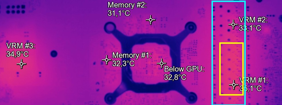
In order to increase efficiency, not all phases have to be controlled equally and to the full extent at low loads. This works in a similar way to the cylinder deactivation in a car. You can also see it with an infrared camera, for example, when only individual areas under the switching regulators show higher temperatures in idle or normal desktop mode (Word etc.). Unfortunately, this cannot be read out by software, only measured at the PWM nodes with an oscilloscope.

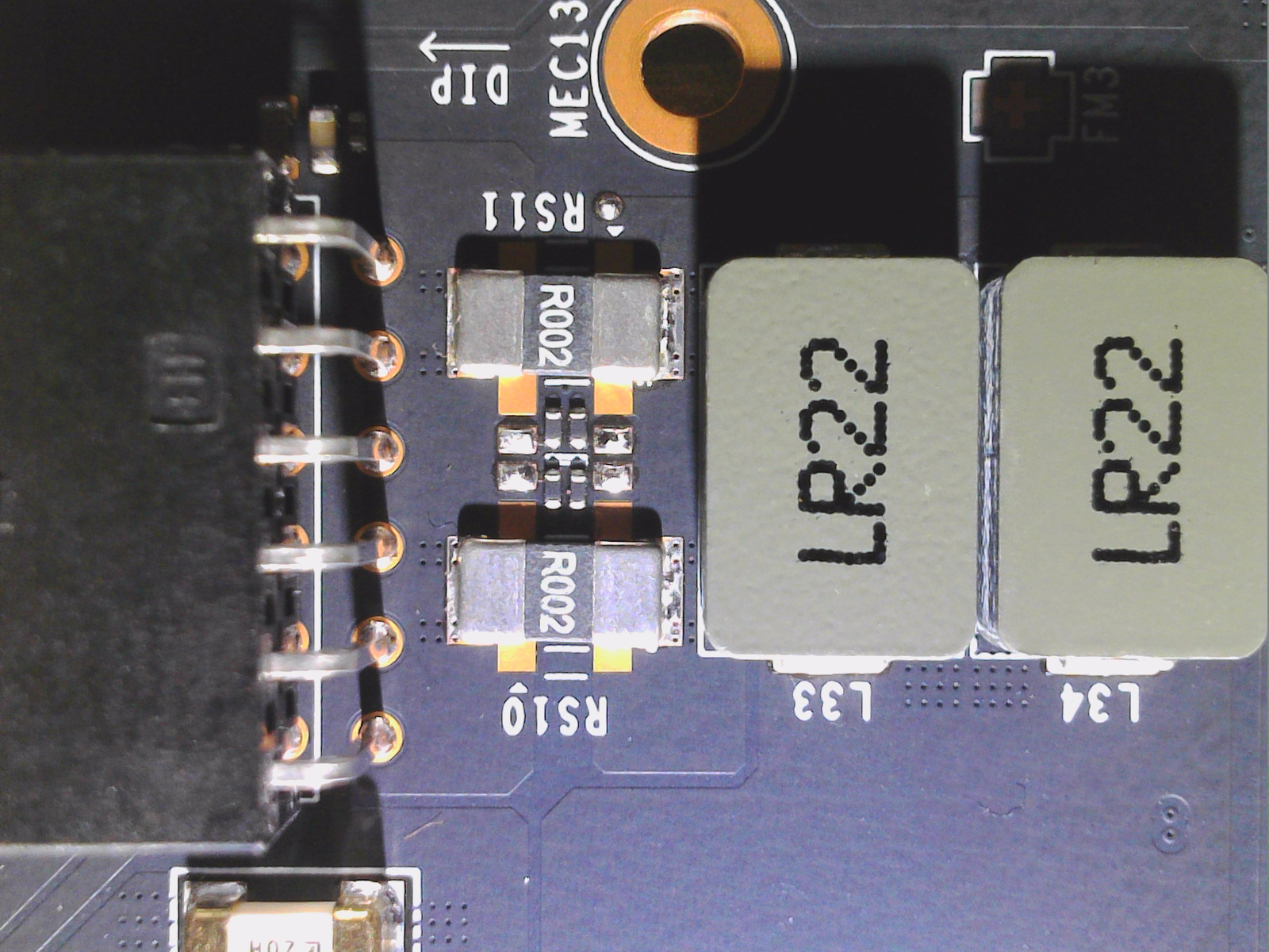
Another interesting nuance is a so-called load balancer. Normally, the switching regulators are supplied from a single source, either the external power connector or the mainboard slot (PEG). But if you don’t want to overload the slot (the PCI SIG specifies a maximum of 5.5 amps on 12 volts) and still don’t have enough power with the external connection, then it can be quite useful to intelligently split one of the switching regulators (or one of the phases) to both sources. If you don’t do that, you’ll end up with some bad luck in a situation like the AMD Radeon RX 480 at the time, where the manufacturer thought they could get by with an external 6-pin to imply efficiency.

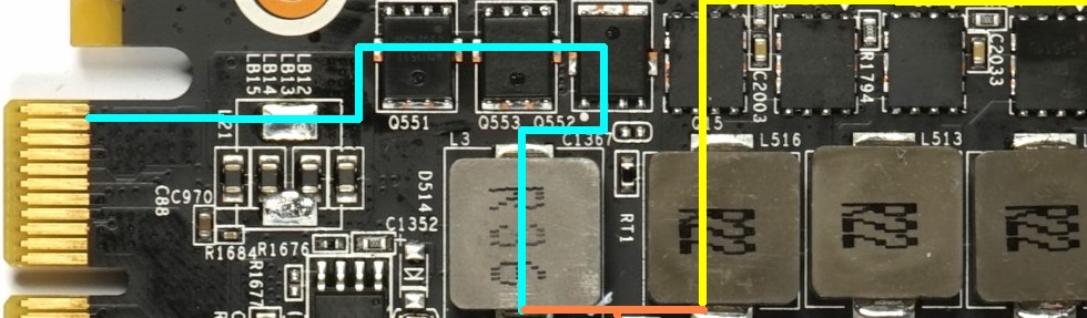
The load balancer, on the other hand, uses both sources proportionally, which can even be controlled in the ideal ratio. The picture above shows the discrete switching regulator from the PEG (turquoise) and the corresponding switching regulator from the PCIe connector (yellow), both driving the same PWM node (orange). So you use two voltage regulators in parallel or alternating, separated on the input side, with a common output, analogous to a real parallel circuit.


Kommentar

Lade neue Kommentare

D
Deridex

Urgestein

2,214 Kommentare 849 Likes

Schöner Artikel, auch wenn das Thema aus meiner Sicht etwas stark vereinfacht wurde. Auch redet zumindest in meinem Umfeld die EMV beim Schaltungsdesign sehr stark mit.

Was man noch erwähnen sollte: Auch MLCCs können gut hörbare Geräusche machen, weswegen man die Schaltungen nicht einfach mit MLCCs bewerfen kann, ohne das vorher genau zu überdenken und zu kontrollieren.
Edit: Habe vergessen zu erwähnen: Kleber mit einem hohen Lösemittelanteil können auch negative Auswirkungen haben.

Antwort Gefällt mir

F
Falcon

Veteran

114 Kommentare 117 Likes

Leider steht die durch die Platine verursachte Geräuschkulisse bei den Herstellern von Grafikkarten im Lastenheft sehr, sehr weit hinten, wenn überhaupt.

Zu Zeiten von Röhrenfernsehern gabs diverse Handwerksbetriebe die sich darauf spezialisiert hatten die Platinen der verbauten Geräte ruhig zu Stellen. Sei es durch bessere Bauteile oder durch Vergießen mit speziellen Harzen.

Die Anmerkung das Karten nach Umbau auf FullCover plötzlich lauter wurden gilt auch umgekehrt.
Hatte schon mehrere Fälle bei denen die Karte nach Umbau auf Wakü leiser wurde, weil die schön weichen Pads oder Thermal Putty die Spulen mechanisch gedämpft hat.

Leider gibts viele Ursachen und auch zwei gleiche Kartenmodelle können brutal unterschiedlich Zirpen/Summen/Knarren.

Es bleibt für den Endkunden wohl noch lange eine Lotterie.

Antwort Gefällt mir

Igor Wallossek

1

10,212 Kommentare 18,900 Likes

Ich kann Dir ein Geheimnis verraten: da steht meist gar nichts drin. :D

Es gibt das Referenzdesign als Empfehlung von AMD bzw. NVIDIA, dazu ein paar Bereiche, wo nichts abgeändert werden darf (z.B. bei der RAM-Anbindung, diese Tracks sind fix vorgegeben) und physikalische Grenzen, die man aber fast immer nur in Richtung Kosten auslotet.

Das größte Problem ist aus meiner Sicht das minimalistische Bemessen der Baulemente auf der Ausgangsseite. Man führt die Schaltfrequenz an die 400 KHz oder drüber, und nimmt dann nur das Kleinste, was gerade noch so passt. Dann hofft man, dass die Teillastbereiche bis zum Maximum bestens abgefedert sind. Was da aber schiefgehen kann, ist die Toleranz bei den Baulementen. Einerseits hat man da die Fertigung und bei Spulen ist das echt manchmal wie Lotto und andererseits sind da die Temperaturen, weil nie alle Bereiche identisch heiß werden. Man müsste immer überdimensionieren und die Temperaturfenster riesig halten, nur wird es dann teuer und oft auch zu groß.

Ich habe aus ursprünglich 7 Seiten Langtext fast einen halben Tag wie blöd rausgekürzt, was m.E. das normale Schulwissen zu weit übersteigt. Es soll ja kein technischer Aufsatz werden, weil man dann den Großteil der Leser liegen lässt. Dann sind diese Seiten übrig geblieben, die aber vielen auch noch zu komplex sein dürfte, Das ist ein Kompromiss, den man kaum hinbekommt.

EMV, jaaa. Aber. Die haben so Ihre Basics, die einmal ausgemessen einfach immer wieder rumkopiert oder nur leicht abgewandelt werden. Das geht eigentlich fast immer schief, nur interessiert es leider keinen so recht. Schönes Beispiel: ich wollte gestern meine 4090 FE ohne Backplate im laufenden Betrieb mit dem iPhone filmen, auch um noch ein paar Betriebsgeräusche aufzunehmen. Da läuft das Smartphone an manchen Bereichen plötzlich Amok, bis hin zum Neustart :D

Antwort 5 Likes

Klicke zum Ausklappem
RedF

Urgestein

4,668 Kommentare 2,553 Likes

Die aktuellen XFX karten haben den ruf nicht oder wenig zu fiepen.
Meine ist auch stumm, aber wenn ich lese was Igor schreibt ist das warscheinlich auch nur zufall.

Antwort Gefällt mir

ssj3rd

Veteran

218 Kommentare 155 Likes

Meine 3090FE hatte Spulenfiepen aus der Hölle, RMA gemacht und das zweite Modell war sogar noch etwas schlimmer, dann frustriert aufgegeben…

Meine jetzige 4090 Strix hat dagegen zum Glück nur leichtes/leises Spulenfiepen.

Mal ein Tipp zum Testen des Fiepen aus dem Luxx Forum:
Red Dead Redemption 2 eignet sich da hervorragend (alles aufdrehen auf MAX), Spiel starten und lauschen:
Da singt es es dann bei (fast) jeden, selbst mit UV und Framerate Begrenzung, geht schon in den Menüs los.

Isr ein wirklich guter Test um herauszufinden wie das worst case fiepen bei einem klingt bzw ob es überhaupt da ist.
Wer in dem Game kein fiepen vernimmt hat wahrlich eine gute Karte erwischt.

Antwort 2 Likes

S
Staarfury

Veteran

257 Kommentare 206 Likes

Auf Seite 3 bei der Beschreibung des Schaltvorgangs fehlten mir eigentlich nur noch ein paar rote Blutkörperchen, die Sauerstoffkugeln rumtragen, um mich komplett in die Jugend zurückzuversetzen. :ROFLMAO:

Antwort 2 Likes

Steffdeff

Urgestein

731 Kommentare 691 Likes

Auf Seite 3 musste ich spontan an Otto‘s „Der menschliche Körper“ denken!
Das macht einen kalten verregneten Tag gleich ein wenig angenehmer.

Danke für den Artikel. Ich bin zwar nicht vom Fach, habe aber etwas gelernt!

Antwort Gefällt mir

ianann

Veteran

336 Kommentare 231 Likes

Interessant fand ich für mich - neben den vielen anderen Einblicken - der Teil, in dem Du auf die unnötige Kühlung der Spulen eingehst. Bei der 4090 FE werden diese - wenn ich es richtig im Kopf habe - gar nicht gekühlt, mit dem EWKB Wasserblock jedoch schon.

Müssten die Wasserblock-Hersteller nicht um diese Thematik wissen und dies in den Entwurf der Blöcke einbeziehen?
Bedeutet ich kann die vergleichsweise fetten Pads auf den Spulen bedenkenlos weglassen?
Hätte dann uU auch den Vorteil, dass ein insgesamt noch besserer "Fit" des Blocks zu erzielen wäre.

Antwort Gefällt mir

F
Falcon

Veteran

114 Kommentare 117 Likes

War ja klar... :rolleyes:

@ianann

Jupp, kannst es mit oder ohne Pads auf den Spulen probieren.

Antwort Gefällt mir

ianann

Veteran

336 Kommentare 231 Likes

Weshalb sollen die denn laut WaKüBlock Hersteller "be-paddet" werden?
Versucht man damit vielleicht den "Sekundenklebertrick" nachzustellen und die Schwingungen zu reduzieren?

Antwort Gefällt mir

Ghoster52

Urgestein

1,417 Kommentare 1,077 Likes

Man wird alt wie ne Kuh und lernt immer (wieder) noch dazu... :ROFLMAO:
Danke für den Einblick & Hinweis, sollte ich meine 3090 noch mal zerlegen, werde ich die "Fiepis" nicht mehr kühlen.

Seite 3 erinnerte mich auch irgendwie an "Es war einmal... der Mensch" und ich hatte diverse Bilder im Kopf. 😂

Antwort 1 Like

D
Deridex

Urgestein

2,214 Kommentare 849 Likes

Das gefällt mir gar nicht.
Mich würde es interessieren, ob die Teile einen EMV-Test im Labor bestehen würden.

Antwort Gefällt mir

ianann

Veteran

336 Kommentare 231 Likes

Hab's mir selbst gegoogled. Gut zu wissen - werde ich die Tage mal testen.

Antwort Gefällt mir

Igor Wallossek

1

10,212 Kommentare 18,900 Likes

Je nachdem, WAS Du testest :(

Im Conduction Test wird ja zunächst nur der Einfluss AUF die Grafikkarte oder ein Netzteil getestet. Eher uninteressant für den Wellensalat.

View image at the forums

Der viel wichtigere Radiation Test ist eigentlich auch nur auf die CE-Vorschriften ausgegelegt und optimiert, was ich komplett abartig finde, weil...

View image at the forums

... wenn Du Dir die Antenne anguckst, dann sieht man auch, dass es um viel zu hohe Frequenzbereiche geht. Der Bereich unter einem GHz wird kaum noch irgendwo berücksichtigt. Für die Konformitätserklärung will das nämlich leider keiner sehen, die Messbereiche sind m.E. viel zu hoch.

View image at the forums

Antwort 2 Likes

T
Tombal

Veteran

109 Kommentare 28 Likes

Auf Seite #1 sind beim P-Kanal-Mosfet Source und Drain vertauscht oder man müsste ihn durch einen N-Kanal Transistor ersetzen. Übrigens kann man sich die Wirkungsweise so eines Schaltreglers ganz einfach auf andere Weise erklären: mit den beiden Transistoren wird am Ausgang eine Wechselspannung erzeugt, die dann mit Spule und Kondensator (LC-Glied) geglättet wird. Also Eingangsspannung X Tastverhältnis = Ausgangsspannung. Beispiel: ich habe einen Duty-Cycle von 50%, dann ist Uout = 0,5 Uin. Der Regelkreis sorgt natürlich ständig dafür, dass das Tastverhältnis angepasst wird.

Antwort Gefällt mir

Igor Wallossek

1

10,212 Kommentare 18,900 Likes

Naja, das ist ja keine Wechselspannung, sondern eher eine Gleichspannung als Sägezahn. Siehe Seite 2 oben. Die Spule ist der Energiespeicher und der Cap glättet dann die Welligkeit.

BTW:
Schaltbild gespiegelt und gefixt, Danke. Man muss beim Einfügen aus der Bibliothek wirklich aufpassen, abends sieht man sowas nicht mehr :D

Antwort 2 Likes

D
Deridex

Urgestein

2,214 Kommentare 849 Likes

Ich habe es beim Überfliegen vom Artikel auch übersehen.

Btw ich habe grad kurz nach den EMV Grenzwerten bezüglich CE gesucht. Was ich gefunden habe kommentiere ich lieber nicht.

Antwort Gefällt mir

Goliath1985

Mitglied

16 Kommentare 4 Likes

Bei mir ist es mit dem Fullcover Backplate der GPX- A (Wakü ) auf einmal so laut geworden das man es durch die Tür gehört hat. Allerdings nur wenn ich diese Festverschraube. Hab Sie nun einfach unverschraubt oben drauf liegen. Jetzt macht die Karte keinen Mucks mehr. Also ( minimal was Sie auch vorher schon hatte ).
"https://www.igorslab.de/community/t...ausreichend-für-rx6800-single-kreislauf.7193/"

Antwort Gefällt mir

Igor Wallossek

1

10,212 Kommentare 18,900 Likes

Ich kann mich nur noch daran erinnern, dass ich bei Gigabyte im R&D mal so ein Protokoll in der Hand hatte und mich über die sehr "praxisnahen" Frequenzbereiche gefreut habe. Ist aber schon länger her

Antwort Gefällt mir

Danke für die Spende


Du fandest, der Beitrag war interessant und möchtest uns unterstützen? Klasse!

Hier erfährst Du, wie: Hier spenden.

Hier kannst Du per PayPal spenden.

About the author

Igor Wallossek

Editor-in-chief and name-giver of igor'sLAB as the content successor of Tom's Hardware Germany, whose license was returned in June 2019 in order to better meet the qualitative demands of web content and challenges of new media such as YouTube with its own channel.

Computer nerd since 1983, audio freak since 1979 and pretty much open to anything with a plug or battery for over 50 years.

Follow Igor:
YouTube Facebook Instagram Twitter

Werbung

Werbung