Basics GPUs Graphics Practice Reviews

Power Supply in Graphics Cards explained – Switching Voltage Regulators, PWM Controler, true Phases and the annoying “Coil Whining” | Reminder

I wrote today’s article less than a year ago, so it’s not really “retro” yet, but somehow it’s time to bring it back up in this section on Saturday. I receive so many letters and enquiries on the subject that I think this article simply deserves to be here, and it certainly takes some of the pressure off me because I don’t always have to copy the link and send it out. And yes, in the meantime I have also dealt with noisy capacitors in conjunction with the coils, but this is not as serious (as often assumed). That will certainly be a new topic. In due course.

Original article from 2022

There are always many inconsistencies and ignorance around the voltage converters of a graphics card and the associated components, as well as the consequences in practical use. Annoying “coil beeping” is only one facet, which is not necessarily due to inferior quality of the coils, but often also to the basic topology of the circuit and the operating parameters. In addition, today we want to (and must) also clear up a legend about the real number of phases and how this differs from the existing number of control loops. Because even here, an unfavorable topology can lead to annoying noises, against the emergence of which the best coil is almost powerless. This is where the dear Mr. Lorentz and the force named after him come into play, but I’ll get to that in a moment.

But I have to say one thing first: The subject is highly complex and not easy for an outsider to get to grips with. I have therefore tried to break most of it down to a generally understandable level and also to leave out some further details, the engineers among you may please forgive me. And yet, not all of the content is easy to understand, so please take some time. Even if one or the other paragraph may sound complicated, you can skip things in between.

The DC/DC converter, the topology, coils and capacitors

Let’s start with the definition of terms, which is not entirely unimportant and serves the better understanding of the further explanations. Since DC voltage cannot be efficiently transformed directly (linear regulators generate far too high losses), DC/DC converters operate in principle like electronic switched-mode power supplies, but without a transformer and therefore not isolated. The DC/DC converters used on graphics cards use pulse width modulation (PWM) and convert the applied 12 V supply voltage into lower voltages, usually between 0.7 to 1.2 volts, depending on the load behavior and clock frequency of the GPU.

The term topology refers to various types of switching operations and combinations of energy storage elements, but we are only interested in transformerless, non-isolated converters that use a common current path between input and output. Today, we are only interested in the so-called buck or down converter. But don’t worry, it won’t be that difficult with the theory now. Important for us: In contrast to the already briefly mentioned linear regulators, which convert the power dissipation completely into heat in order to limit the output voltage, DC/DC switching regulators use the energy storage properties of inductive and capacitive components to transfer a power in individual “portions”. In a graphics card, these energy portions are mainly stored in the magnetic field of an inductor, i.e. the coils we know so well. So now we know what this pieces in the voltage regulator are actually used for.

The mode of action of the buck converter

Incidentally, the switching regulator ensures that only the energy required for the load currently demanded by the GPU is transferred into each packet, which is why this topology is very efficient. The following drawing of a so-called buck converter shows the highly simplified structure of a switching regulator, where the switch symbolically stands for the MOSFET bridge, which is controlled by the so-called PWM controller, which generates at least one phase (as shown here in the picture). The losses are significantly lower than with a linear regulator and the efficiency of the entire circuit can range from about 85% to over 95%, depending on the driven effort in circuit and components.

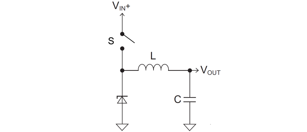
Now let’s consider the switch in the form of the PWM-controlled switching regulator. Through it, current flows via a momentarily closed switch into an inductive circuit (our dearly beloved coils), which leads to the output current. When the desired voltage value is reached (depending on the GPU’s clock and load), the switch opens at the beginning of the circuit and thus does not consume much more current than it really needs at the end. If the current stored in the coil (inductor) now falls below a certain level, the switch automatically closes again and the circuit starts anew. This is first the theory, where the capacitor C is used for smoothing. Also, you’ll read all of this again completely simplified on the next pages when it comes to coil whining.

In order to transfer this desired energy from the input to the output in controlled quantities, a very complicated control process is required. The type of control used on the graphics board is PWM (Pulse Width Modulation), where the amount of energy to be transferred from the input (Ue) to the output (Ua) is modulated by a pulse of variable width at a fixed time interval. The relative duty cycle of the PWM is the ratio of the period (in which energy flows from the source) to the period T (as the inverse of the switching frequency). We won’t be interested in that here for now, but we’ll come back to it in a moment when it comes to using multiple phases.

What is a high-side and a low-side?

The usual MOSFETs (i.e. our VRM) are usually overdriven when used as switching transistors, whereby the drain-source resistance is always at the minimum and thus the power losses in the switch remain low. As long as the gate voltage is significantly greater than the threshold voltage, the MOSFET is in saturation over the entire load range. We can see on the schematic below that there are even two MOSFETs, one switching to ground (low voltage side, Low Side) and the other switching to VIN+ (high voltage side, High Side). The exact operation of these two MOSFETs will be explained in a simplified way on the next pages, at this point we only take note of the structure.

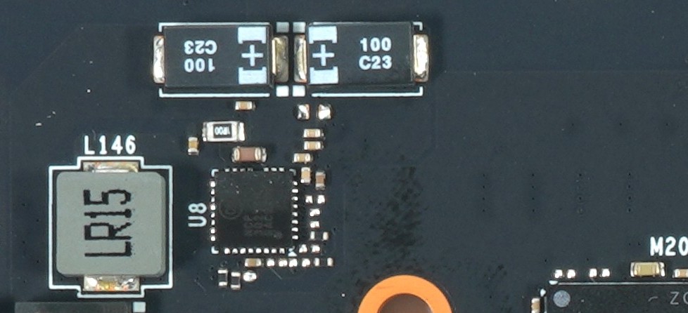
What is important for efficiency, however, are the variations in the structure and components. You can build the high-side, low-side and gate driver discretely and thus need at least three components. Often, a second MOSFET is added in parallel for the low side in order to better divide the high currents and thus reduce the internal resistance. A classic example of such a low-cost solution can be seen in the following picture, and I can already reveal it: here the coils are chirping like crazed cicadas on ecstasy.

If all these components are packed into a common package, then a single IC is created as a so-called DrMOS (Driver + MOSFET). If further control features and intelligent monitoring such as TMON (temperature) and IMON (current, MOSFET-DCR) are added, even highly complex Smart Power Stages (SPS) are created, with which extremely efficient circuits can be built. However, the advantage lies not only in the very high efficiency, but also in the significantly lower space requirement of such a component. If you only use discrete components and no PLC, you have to resort to the so-called Inductor-DCR for current monitoring, i.e. a much less accurate current measurement via the inductive resistance of the respective filter coils in the output area.

Smart Power Stages

The switching frequency of the voltage regulator and the size of the coils

The size of the switching and storage elements of the switching controller are always inversely proportional to the switching frequency used. Conversely, this also means that the amount of energy stored in a coil is proportional to the frequency. And this in turn means that for a constant amount of energy, one could simply halve the inductance L by simply doubling the frequency. Unfortunately, this cannot be increased endlessly, otherwise there will be high-frequency wave salad. Therefore, an EMC compromise exists that limits the highest switching frequency that can still be used sensibly to approx. 500 kHz.

In the case of our graphics cards, the switching frequencies are usually between 350 and 450 kHz. Each board partner has his own preferences, but must also take into account which components are present, which currents could flow and how the distribution and number of phases looks. This is because this issue is highly important and also determines the efficiency of the voltage transformers and the possible occurrence of coil buzzing or beeping. Yes, it’s been a bit much theory so far, which I’ve tried to simplify as much as possible, it’s just that you really need to know these things. Without this knowledge, coils are exchanged wildly and almost always only on suspicion, and in the worst case, the graphics card is even destroyed, despite the supposedly better quality of the components.

The fact is, however, that these measurements can also have a certain influence on the coil noise and in the worst case it then almost doesn’t matter which quality class the coils used come from. An inexpensive card with a power supply that’s on the edge will therefore almost always be very audible, because savings had to be made somewhere. However, the entire block of all voltage transformers must then be regarded as an acoustically failed work of art.

Kommentar

Lade neue Kommentare

D
Deridex

Urgestein

2,213 Kommentare 846 Likes

Schöner Artikel, auch wenn das Thema aus meiner Sicht etwas stark vereinfacht wurde. Auch redet zumindest in meinem Umfeld die EMV beim Schaltungsdesign sehr stark mit.

Was man noch erwähnen sollte: Auch MLCCs können gut hörbare Geräusche machen, weswegen man die Schaltungen nicht einfach mit MLCCs bewerfen kann, ohne das vorher genau zu überdenken und zu kontrollieren.
Edit: Habe vergessen zu erwähnen: Kleber mit einem hohen Lösemittelanteil können auch negative Auswirkungen haben.

Antwort Gefällt mir

F
Falcon

Veteran

114 Kommentare 117 Likes

Leider steht die durch die Platine verursachte Geräuschkulisse bei den Herstellern von Grafikkarten im Lastenheft sehr, sehr weit hinten, wenn überhaupt.

Zu Zeiten von Röhrenfernsehern gabs diverse Handwerksbetriebe die sich darauf spezialisiert hatten die Platinen der verbauten Geräte ruhig zu Stellen. Sei es durch bessere Bauteile oder durch Vergießen mit speziellen Harzen.

Die Anmerkung das Karten nach Umbau auf FullCover plötzlich lauter wurden gilt auch umgekehrt.
Hatte schon mehrere Fälle bei denen die Karte nach Umbau auf Wakü leiser wurde, weil die schön weichen Pads oder Thermal Putty die Spulen mechanisch gedämpft hat.

Leider gibts viele Ursachen und auch zwei gleiche Kartenmodelle können brutal unterschiedlich Zirpen/Summen/Knarren.

Es bleibt für den Endkunden wohl noch lange eine Lotterie.

Antwort Gefällt mir

Igor Wallossek

1

10,198 Kommentare 18,815 Likes

Ich kann Dir ein Geheimnis verraten: da steht meist gar nichts drin. :D

Es gibt das Referenzdesign als Empfehlung von AMD bzw. NVIDIA, dazu ein paar Bereiche, wo nichts abgeändert werden darf (z.B. bei der RAM-Anbindung, diese Tracks sind fix vorgegeben) und physikalische Grenzen, die man aber fast immer nur in Richtung Kosten auslotet.

Das größte Problem ist aus meiner Sicht das minimalistische Bemessen der Baulemente auf der Ausgangsseite. Man führt die Schaltfrequenz an die 400 KHz oder drüber, und nimmt dann nur das Kleinste, was gerade noch so passt. Dann hofft man, dass die Teillastbereiche bis zum Maximum bestens abgefedert sind. Was da aber schiefgehen kann, ist die Toleranz bei den Baulementen. Einerseits hat man da die Fertigung und bei Spulen ist das echt manchmal wie Lotto und andererseits sind da die Temperaturen, weil nie alle Bereiche identisch heiß werden. Man müsste immer überdimensionieren und die Temperaturfenster riesig halten, nur wird es dann teuer und oft auch zu groß.

Ich habe aus ursprünglich 7 Seiten Langtext fast einen halben Tag wie blöd rausgekürzt, was m.E. das normale Schulwissen zu weit übersteigt. Es soll ja kein technischer Aufsatz werden, weil man dann den Großteil der Leser liegen lässt. Dann sind diese Seiten übrig geblieben, die aber vielen auch noch zu komplex sein dürfte, Das ist ein Kompromiss, den man kaum hinbekommt.

EMV, jaaa. Aber. Die haben so Ihre Basics, die einmal ausgemessen einfach immer wieder rumkopiert oder nur leicht abgewandelt werden. Das geht eigentlich fast immer schief, nur interessiert es leider keinen so recht. Schönes Beispiel: ich wollte gestern meine 4090 FE ohne Backplate im laufenden Betrieb mit dem iPhone filmen, auch um noch ein paar Betriebsgeräusche aufzunehmen. Da läuft das Smartphone an manchen Bereichen plötzlich Amok, bis hin zum Neustart :D

Antwort 5 Likes

Klicke zum Ausklappem
RedF

Urgestein

4,665 Kommentare 2,553 Likes

Die aktuellen XFX karten haben den ruf nicht oder wenig zu fiepen.
Meine ist auch stumm, aber wenn ich lese was Igor schreibt ist das warscheinlich auch nur zufall.

Antwort Gefällt mir

ssj3rd

Veteran

218 Kommentare 155 Likes

Meine 3090FE hatte Spulenfiepen aus der Hölle, RMA gemacht und das zweite Modell war sogar noch etwas schlimmer, dann frustriert aufgegeben…

Meine jetzige 4090 Strix hat dagegen zum Glück nur leichtes/leises Spulenfiepen.

Mal ein Tipp zum Testen des Fiepen aus dem Luxx Forum:
Red Dead Redemption 2 eignet sich da hervorragend (alles aufdrehen auf MAX), Spiel starten und lauschen:
Da singt es es dann bei (fast) jeden, selbst mit UV und Framerate Begrenzung, geht schon in den Menüs los.

Isr ein wirklich guter Test um herauszufinden wie das worst case fiepen bei einem klingt bzw ob es überhaupt da ist.
Wer in dem Game kein fiepen vernimmt hat wahrlich eine gute Karte erwischt.

Antwort 2 Likes

S
Staarfury

Veteran

257 Kommentare 206 Likes

Auf Seite 3 bei der Beschreibung des Schaltvorgangs fehlten mir eigentlich nur noch ein paar rote Blutkörperchen, die Sauerstoffkugeln rumtragen, um mich komplett in die Jugend zurückzuversetzen. :ROFLMAO:

Antwort 2 Likes

Steffdeff

Urgestein

727 Kommentare 678 Likes

Auf Seite 3 musste ich spontan an Otto‘s „Der menschliche Körper“ denken!
Das macht einen kalten verregneten Tag gleich ein wenig angenehmer.

Danke für den Artikel. Ich bin zwar nicht vom Fach, habe aber etwas gelernt!

Antwort Gefällt mir

ianann

Veteran

336 Kommentare 231 Likes

Interessant fand ich für mich - neben den vielen anderen Einblicken - der Teil, in dem Du auf die unnötige Kühlung der Spulen eingehst. Bei der 4090 FE werden diese - wenn ich es richtig im Kopf habe - gar nicht gekühlt, mit dem EWKB Wasserblock jedoch schon.

Müssten die Wasserblock-Hersteller nicht um diese Thematik wissen und dies in den Entwurf der Blöcke einbeziehen?
Bedeutet ich kann die vergleichsweise fetten Pads auf den Spulen bedenkenlos weglassen?
Hätte dann uU auch den Vorteil, dass ein insgesamt noch besserer "Fit" des Blocks zu erzielen wäre.

Antwort Gefällt mir

F
Falcon

Veteran

114 Kommentare 117 Likes

War ja klar... :rolleyes:

@ianann

Jupp, kannst es mit oder ohne Pads auf den Spulen probieren.

Antwort Gefällt mir

ianann

Veteran

336 Kommentare 231 Likes

Weshalb sollen die denn laut WaKüBlock Hersteller "be-paddet" werden?
Versucht man damit vielleicht den "Sekundenklebertrick" nachzustellen und die Schwingungen zu reduzieren?

Antwort Gefällt mir

Ghoster52

Urgestein

1,412 Kommentare 1,068 Likes

Man wird alt wie ne Kuh und lernt immer (wieder) noch dazu... :ROFLMAO:
Danke für den Einblick & Hinweis, sollte ich meine 3090 noch mal zerlegen, werde ich die "Fiepis" nicht mehr kühlen.

Seite 3 erinnerte mich auch irgendwie an "Es war einmal... der Mensch" und ich hatte diverse Bilder im Kopf. 😂

Antwort 1 Like

D
Deridex

Urgestein

2,213 Kommentare 846 Likes

Das gefällt mir gar nicht.
Mich würde es interessieren, ob die Teile einen EMV-Test im Labor bestehen würden.

Antwort Gefällt mir

ianann

Veteran

336 Kommentare 231 Likes

Hab's mir selbst gegoogled. Gut zu wissen - werde ich die Tage mal testen.

Antwort Gefällt mir

Igor Wallossek

1

10,198 Kommentare 18,815 Likes

Je nachdem, WAS Du testest :(

Im Conduction Test wird ja zunächst nur der Einfluss AUF die Grafikkarte oder ein Netzteil getestet. Eher uninteressant für den Wellensalat.

View image at the forums

Der viel wichtigere Radiation Test ist eigentlich auch nur auf die CE-Vorschriften ausgegelegt und optimiert, was ich komplett abartig finde, weil...

View image at the forums

... wenn Du Dir die Antenne anguckst, dann sieht man auch, dass es um viel zu hohe Frequenzbereiche geht. Der Bereich unter einem GHz wird kaum noch irgendwo berücksichtigt. Für die Konformitätserklärung will das nämlich leider keiner sehen, die Messbereiche sind m.E. viel zu hoch.

View image at the forums

Antwort 2 Likes

T
Tombal

Veteran

109 Kommentare 28 Likes

Auf Seite #1 sind beim P-Kanal-Mosfet Source und Drain vertauscht oder man müsste ihn durch einen N-Kanal Transistor ersetzen. Übrigens kann man sich die Wirkungsweise so eines Schaltreglers ganz einfach auf andere Weise erklären: mit den beiden Transistoren wird am Ausgang eine Wechselspannung erzeugt, die dann mit Spule und Kondensator (LC-Glied) geglättet wird. Also Eingangsspannung X Tastverhältnis = Ausgangsspannung. Beispiel: ich habe einen Duty-Cycle von 50%, dann ist Uout = 0,5 Uin. Der Regelkreis sorgt natürlich ständig dafür, dass das Tastverhältnis angepasst wird.

Antwort Gefällt mir

Igor Wallossek

1

10,198 Kommentare 18,815 Likes

Naja, das ist ja keine Wechselspannung, sondern eher eine Gleichspannung als Sägezahn. Siehe Seite 2 oben. Die Spule ist der Energiespeicher und der Cap glättet dann die Welligkeit.

BTW:
Schaltbild gespiegelt und gefixt, Danke. Man muss beim Einfügen aus der Bibliothek wirklich aufpassen, abends sieht man sowas nicht mehr :D

Antwort 2 Likes

D
Deridex

Urgestein

2,213 Kommentare 846 Likes

Ich habe es beim Überfliegen vom Artikel auch übersehen.

Btw ich habe grad kurz nach den EMV Grenzwerten bezüglich CE gesucht. Was ich gefunden habe kommentiere ich lieber nicht.

Antwort Gefällt mir

Goliath1985

Mitglied

16 Kommentare 4 Likes

Bei mir ist es mit dem Fullcover Backplate der GPX- A (Wakü ) auf einmal so laut geworden das man es durch die Tür gehört hat. Allerdings nur wenn ich diese Festverschraube. Hab Sie nun einfach unverschraubt oben drauf liegen. Jetzt macht die Karte keinen Mucks mehr. Also ( minimal was Sie auch vorher schon hatte ).
"https://www.igorslab.de/community/t...ausreichend-für-rx6800-single-kreislauf.7193/"

Antwort Gefällt mir

Igor Wallossek

1

10,198 Kommentare 18,815 Likes

Ich kann mich nur noch daran erinnern, dass ich bei Gigabyte im R&D mal so ein Protokoll in der Hand hatte und mich über die sehr "praxisnahen" Frequenzbereiche gefreut habe. Ist aber schon länger her

Antwort Gefällt mir

Danke für die Spende


Du fandest, der Beitrag war interessant und möchtest uns unterstützen? Klasse!

Hier erfährst Du, wie: Hier spenden.

Hier kannst Du per PayPal spenden.

About the author

Igor Wallossek

Editor-in-chief and name-giver of igor'sLAB as the content successor of Tom's Hardware Germany, whose license was returned in June 2019 in order to better meet the qualitative demands of web content and challenges of new media such as YouTube with its own channel.

Computer nerd since 1983, audio freak since 1979 and pretty much open to anything with a plug or battery for over 50 years.

Follow Igor:
YouTube Facebook Instagram Twitter

Werbung

Werbung