


After hearing the unmistakable sound of the of silicone glue and indium solder letting go, the moment of truth has come. From the side, you can already see how the IHS has been displaced from the carriage and adhesive residue is revealed underneath.
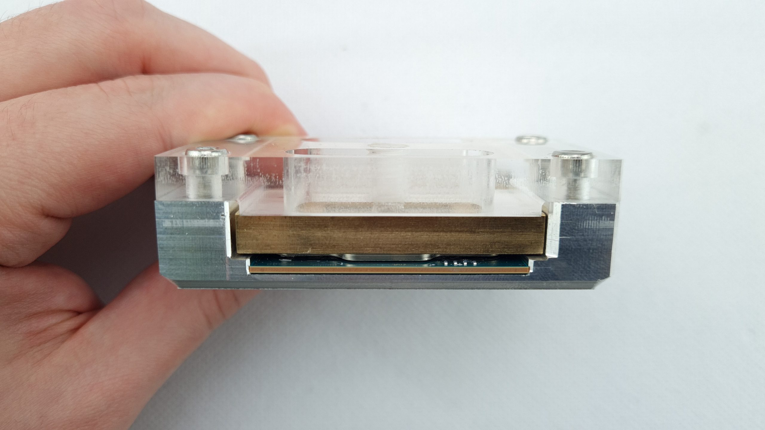
After loosening the screws, it is also clearly visible from above how the heatspreader on the package has been moved to the right.
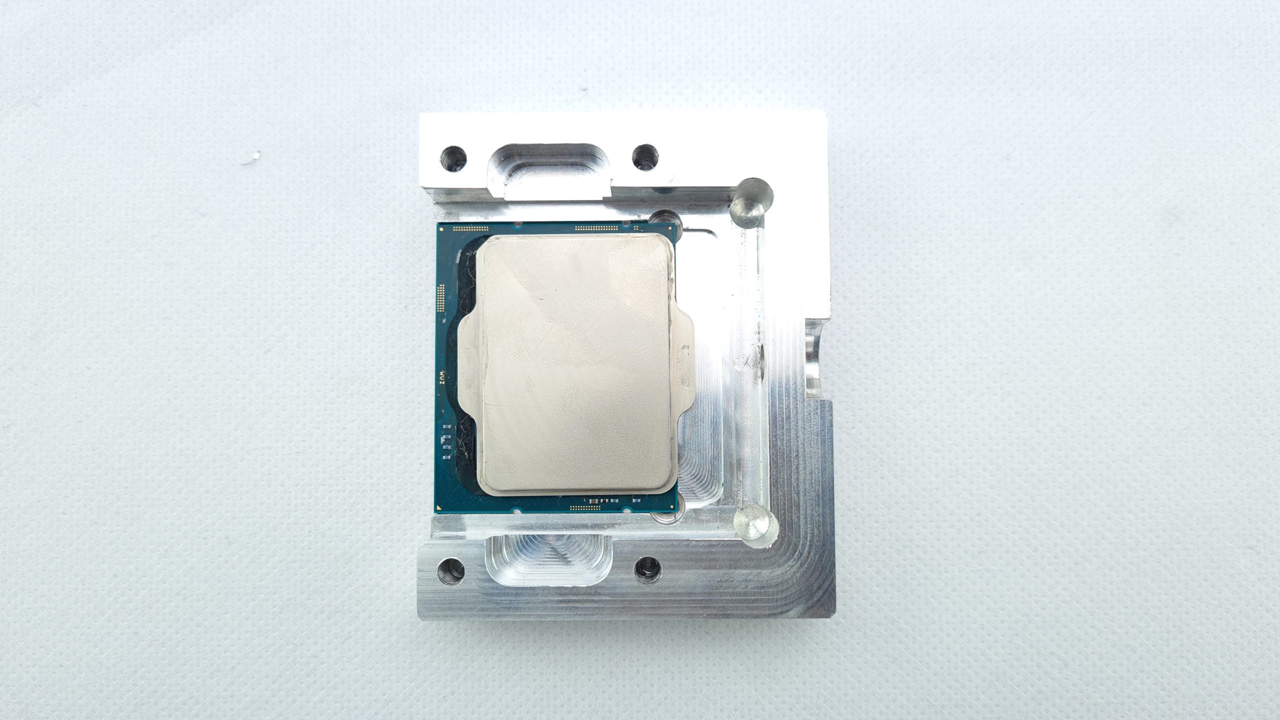
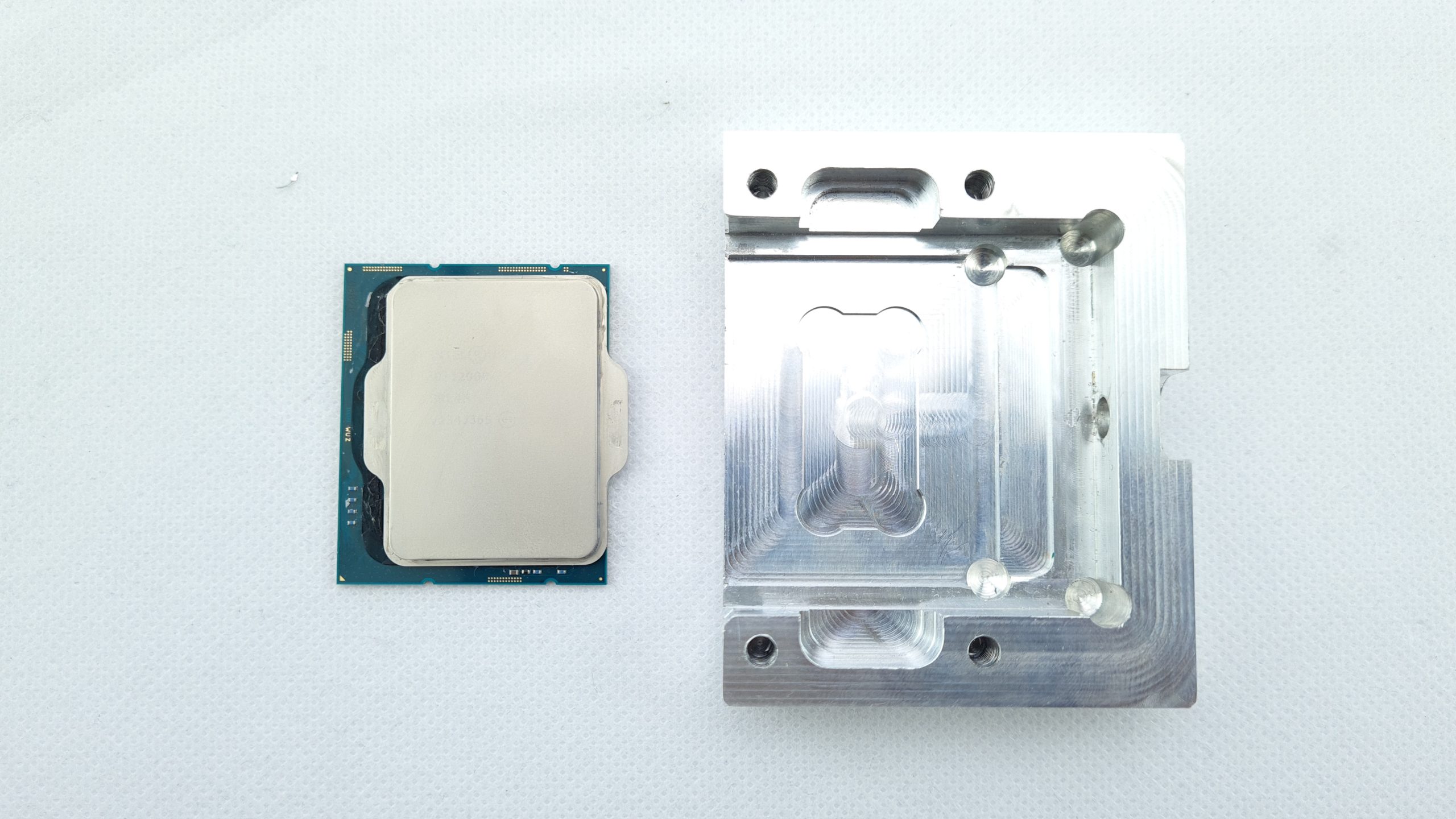
The CPU can be easily removed from the tool again and due to a certain residual adhesion of the glue, it also remains in one piece for the time being. Now the IHS can simply be carefully lifted off the package.
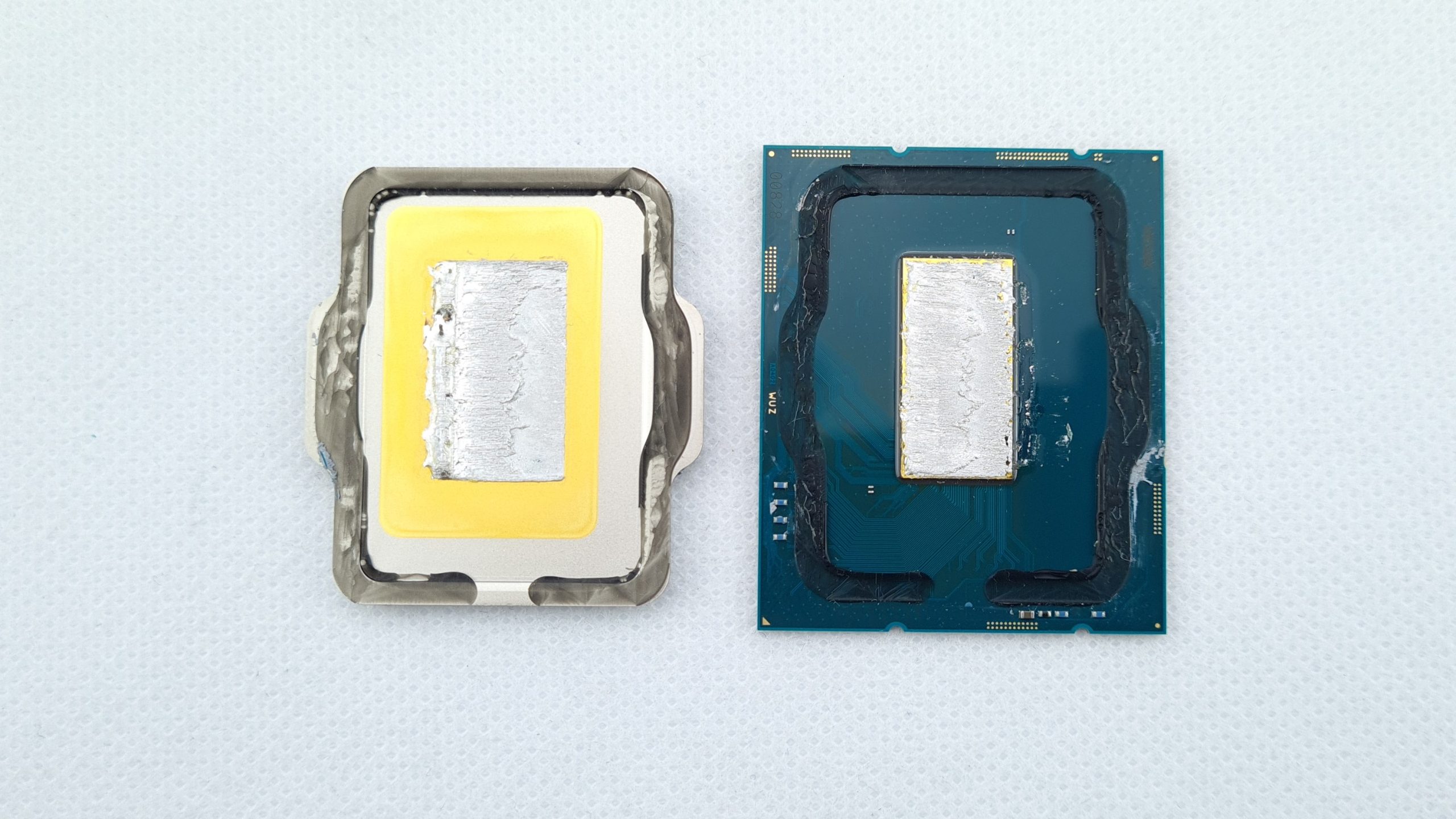
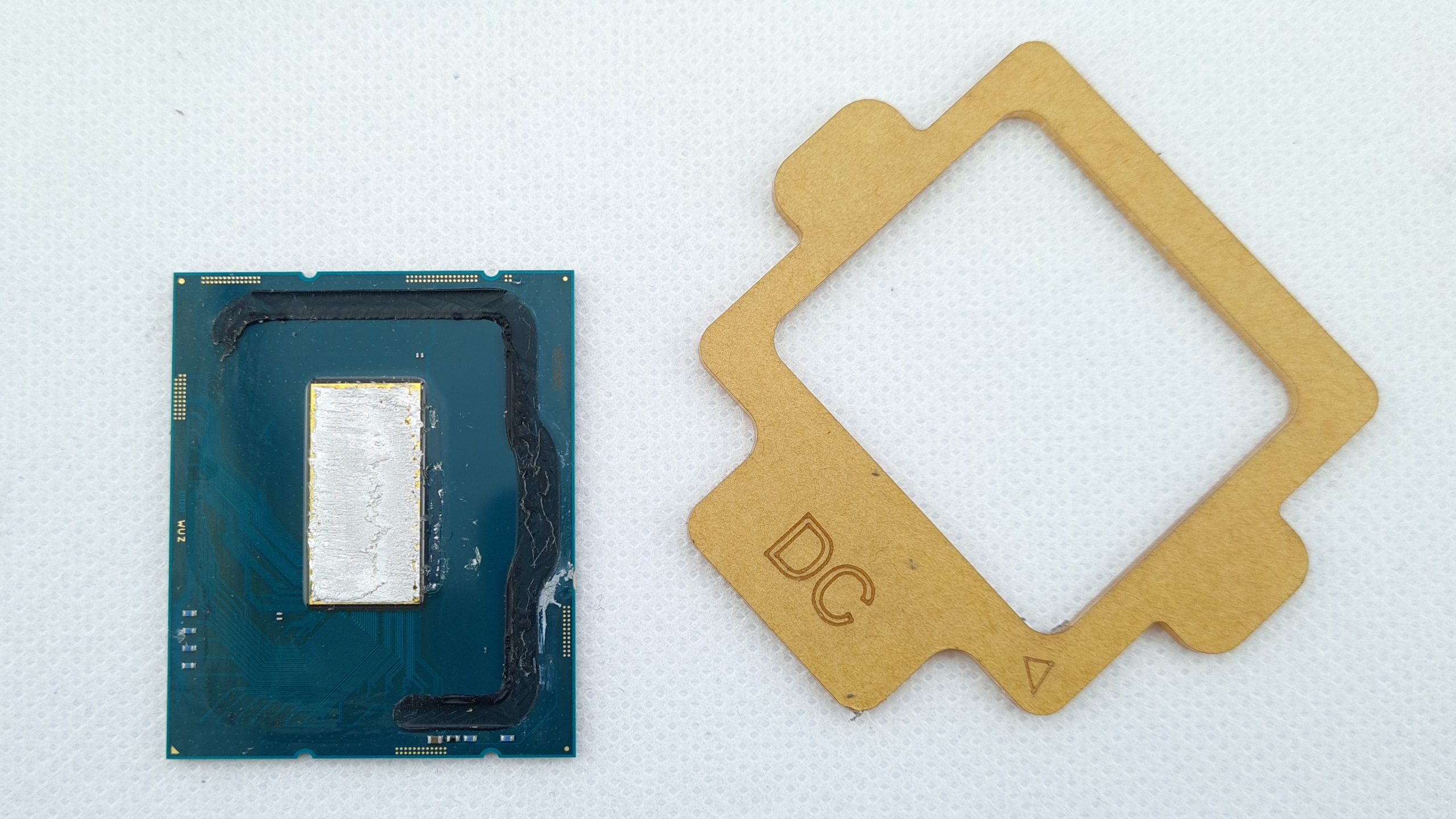
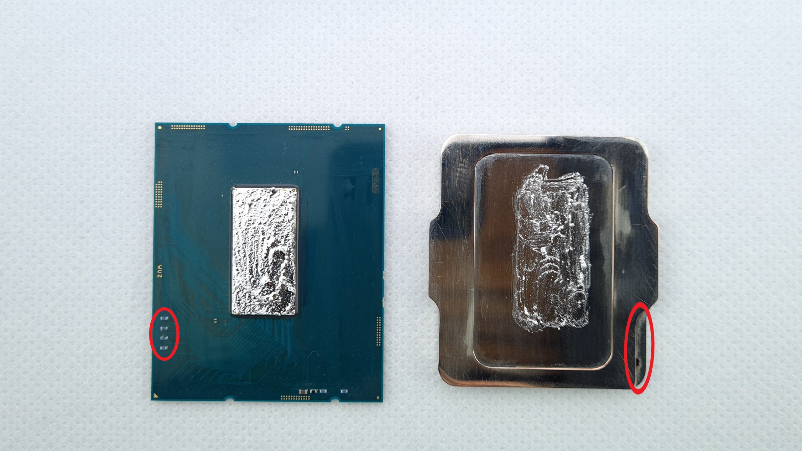
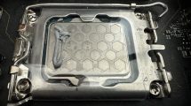
If all has gone well, the inner workings of the CPU emerge unscathed: the underside of the IHS is coated with gold to allow better adhesion and heat conduction for the indium solder. The latter is distributed in crude amounts between the die and IHS, showing an accumulation produced by the shear motion during delidding. It is also noticeable that the CPU, solder and gold plating are not centered, but slightly offset upwards and to the side.
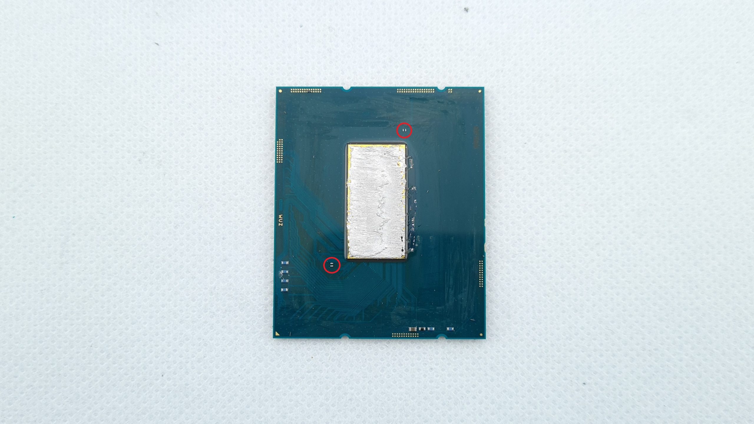
Now it’s time to clean the CPU, first from the residues of the black silicone glue. For this purpose, the included acrylic stencils are very suitable, which are hard enough to scrape off the glue, but soft enough not to damage the package. Nevertheless, extreme caution is again required to avoid damaging or tearing off the SMD components. In addition to the two groups of four components at the edge of the package, there are two pairs of much smaller components that must also be considered.
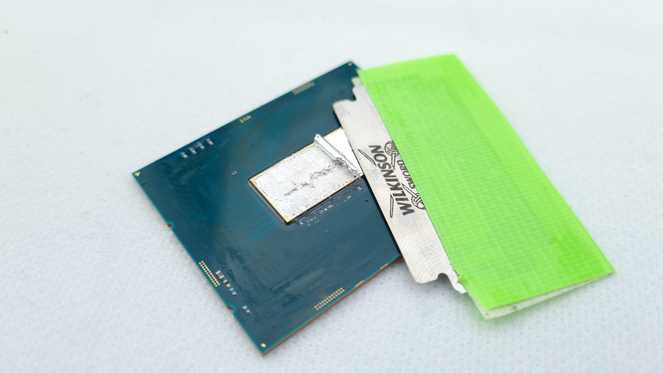
After the adhesive residues have been cleaned up, the indium solder still has to be scraped off the die. Especially here you should pay more attention to the small SMD components near the die. For this, I use a razor blade with fabric tape as a handle and carefully scrape along the dies without damaging their edges.
Somewhat reminiscent of a fancy dessert dish, don’t you think?
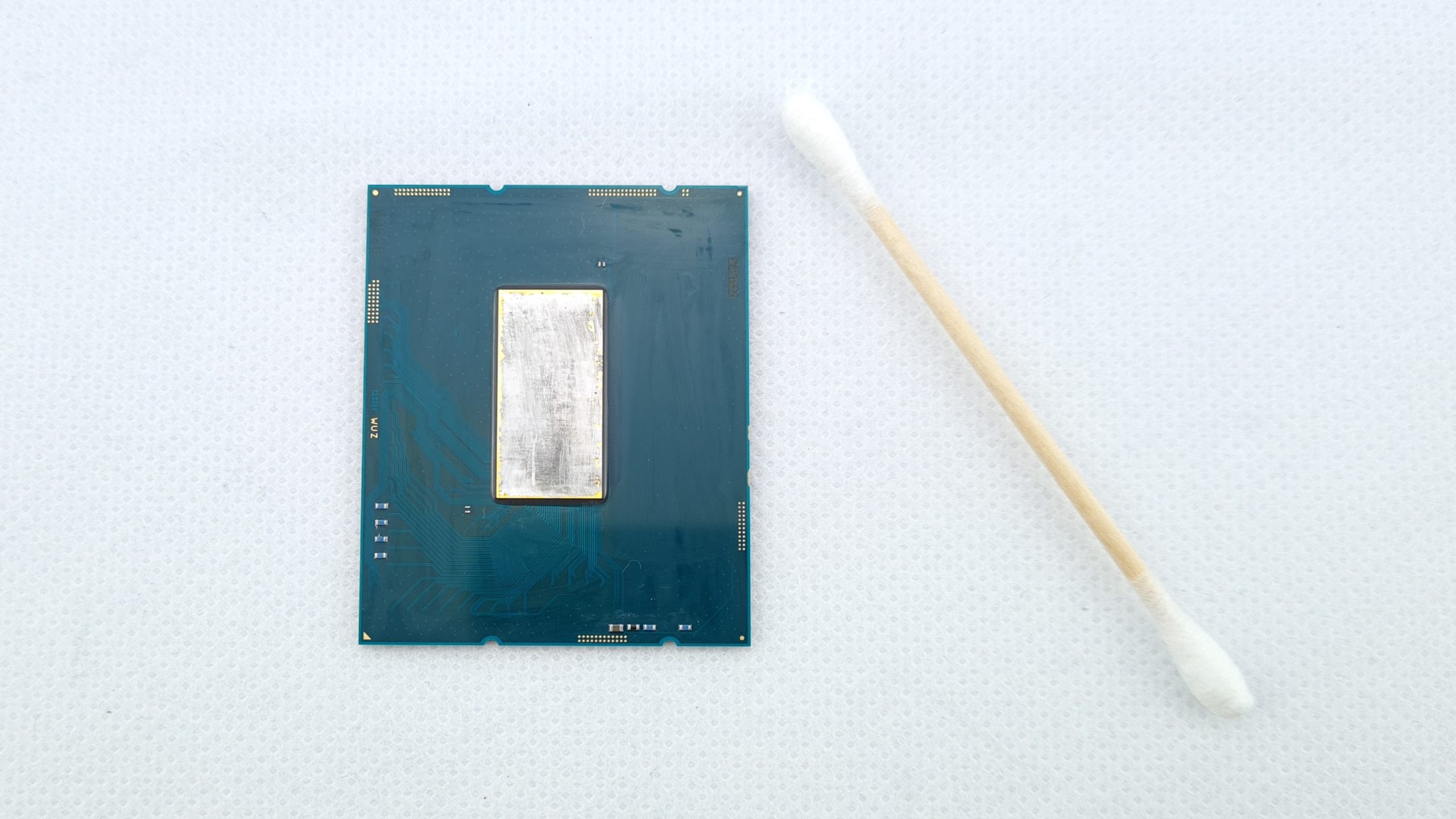
After the the majority of the residues are removed, I clean the die and the package again with isopropanol and cotton swabs. This is because the CPU should be completely free of residues both for the block to fit as evenly as possible and for the new heat transfer medium to adhere well. If you want to be on the really safe side, you can cover the two pairs of smd components next to the die with capton tape, nail polish or similar. In the event that some of the liquid metal could get loose and drip onto the package, this way you can prevent a short and probably lots of trouble shooting.
Now it’s time to get down and dirty, enter liquid metal. This is now used as a new thermal interface material between the die and the water block and has much higher thermal conductivity than conventional pastes, at least at temperatures above 0 °C. Here I use Coollaboratory Liquid Ultra, although other liquid metal products also work. Less is more here and it is quite sufficient if both sides are thinly wetted. Since the die is not quite centered, as I said, I also make the application on the cold plate slightly offset accordingly. Here also orientation matters, as there is a special cutout in the coldplate for the smd components in the bottom left of the package.
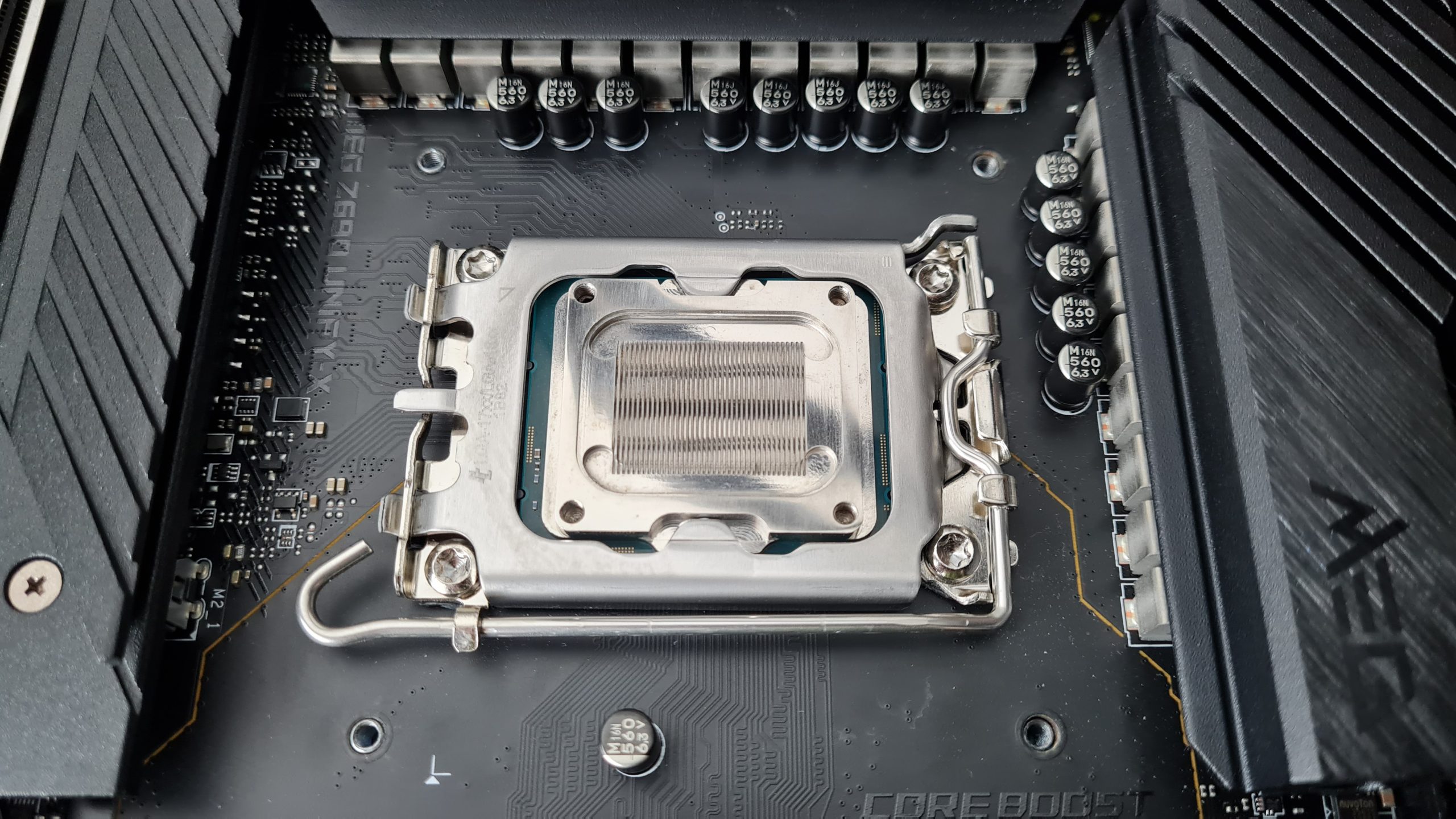
Now the question is whether or not to re-glue the cold plate back to the CPU as an effective IHS replacement. I decided against it and instead just let the motherboard’s ILM hold everything in place.
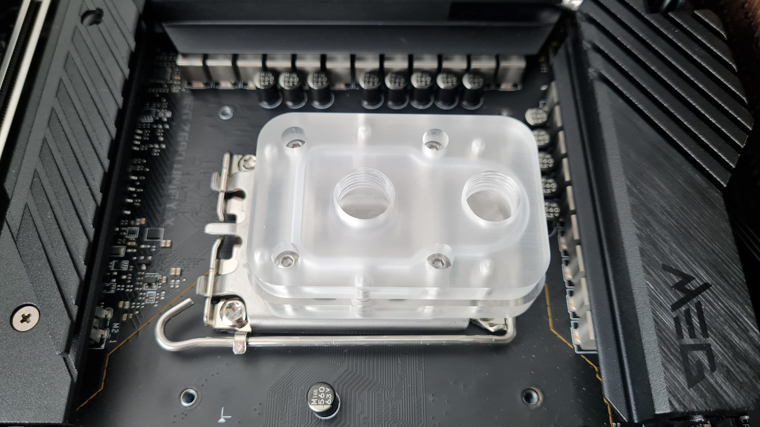
The next steps are comparatively simple. The acrylic part of the water block is simply screwed to the base plate again, whereby the O-ring should of course be clean and the screws should always be tightened crosswise for better force distribution. In terms of torque there is no recommendation from the manufacturer or any measurement results from me. However, when you use the included allen wrench, you can feel it slightly twisting once the screws become tightened – that’s where you should stop.
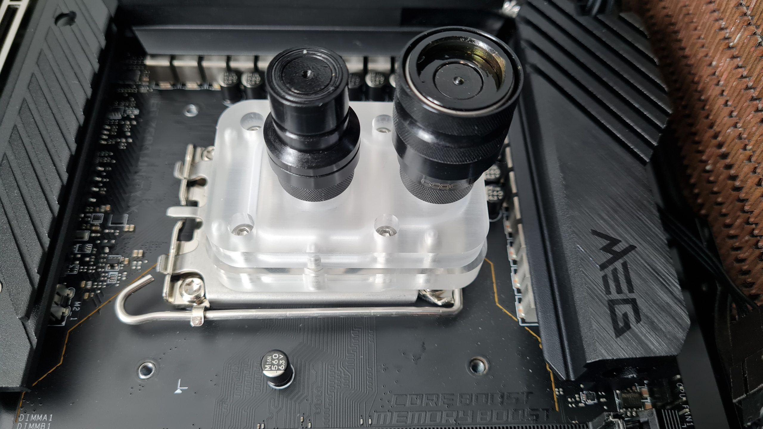
Now just screw in the fittings as with any water block, fill the loop and that’s it. Since removing the CPU and block effectively requires disassembling the latter and draining the water to do so, I use quick-release couplings from Alphacool here. Oh yes, and after the loop is filled and the system is switched on for the first time, now is the moment to find out if the CPU has survived the whole procedure. Whether the whole effort was worth it now and how the temperature savings look like, you can find out on the next page!


56 Antworten
Kommentar
Lade neue Kommentare
Mitglied
Urgestein
Veteran
1
Urgestein
Veteran
Mitglied
Mitglied
1
Veteran
Moderator
Urgestein
Mitglied
Veteran
Urgestein
Veteran
Urgestein
Urgestein
Urgestein
Alle Kommentare lesen unter igor´sLAB Community →