Cooling CPU Editor's Desk Practice Reviews Watercooling

Supercool Computers Direct-Die waterblock and delid tool for Intel Alder Lake Review| Intel Core i9-12900K in Pain

Construction of the delid tool

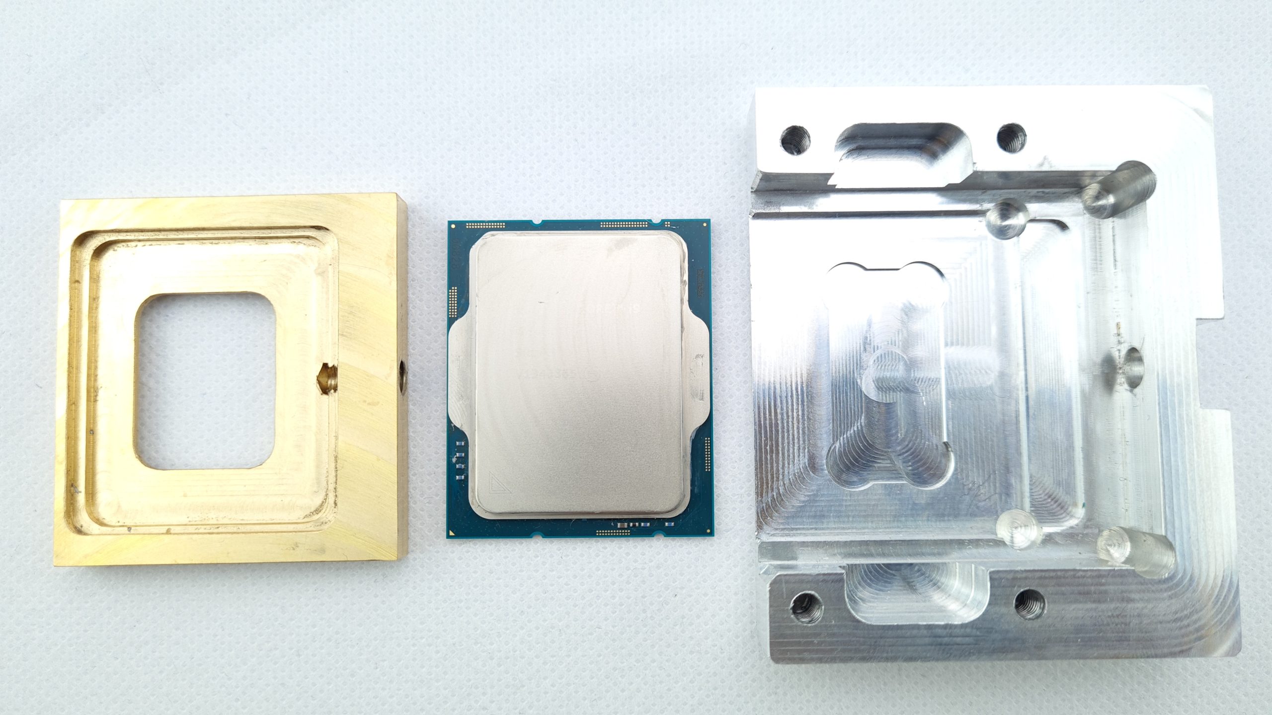
Now let’s have a look at the delid tool, which is used to “behead” the CPU. This is needed to effectively separate the glued and soldered IHS from the package and die of the CPU with a precise shearing motion. Such a delid tool should therefore be manufactured accordingly precise and exact in order not to damage or even destroy the CPU. Because often the smallest error here means silicon death.

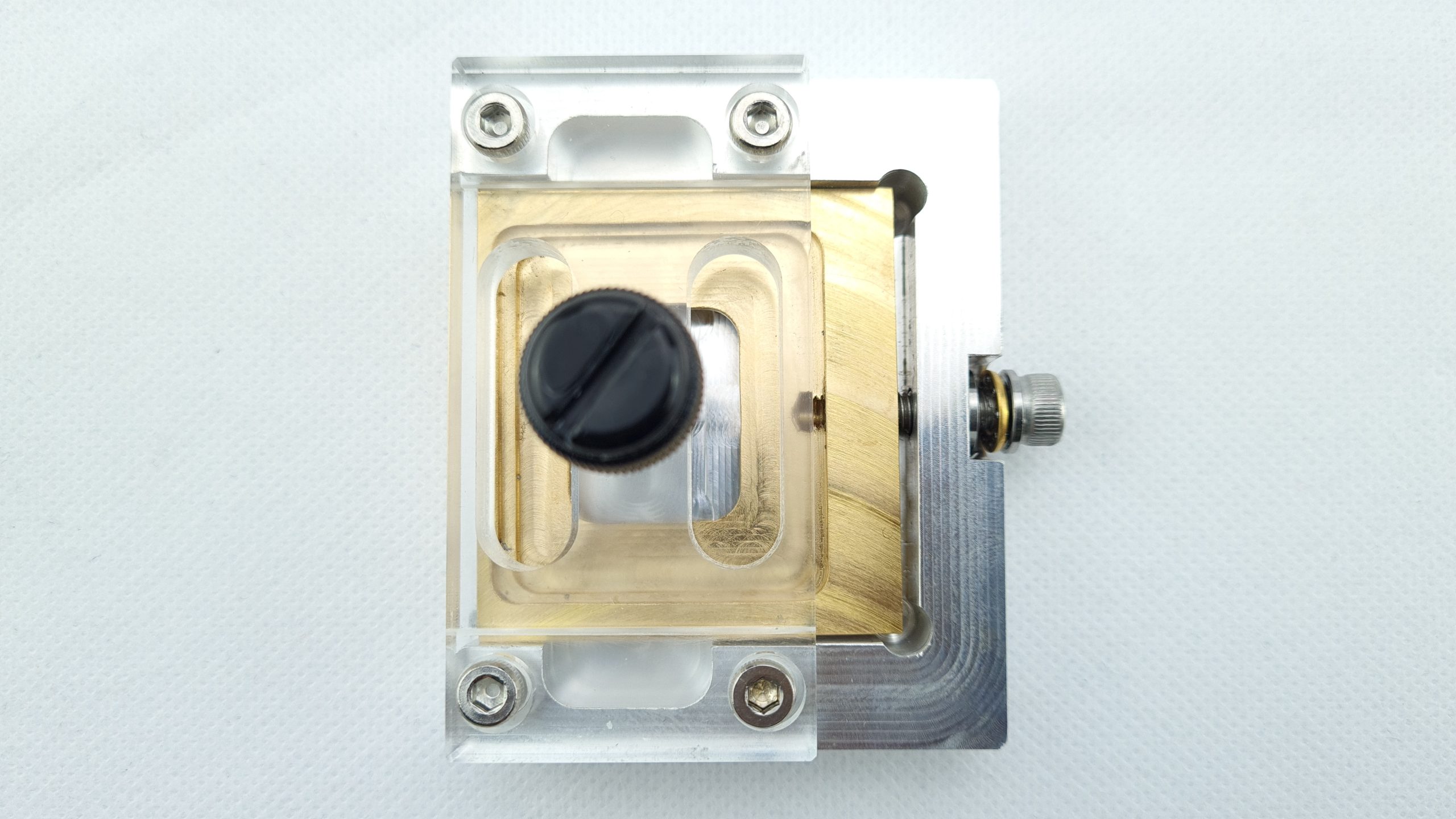
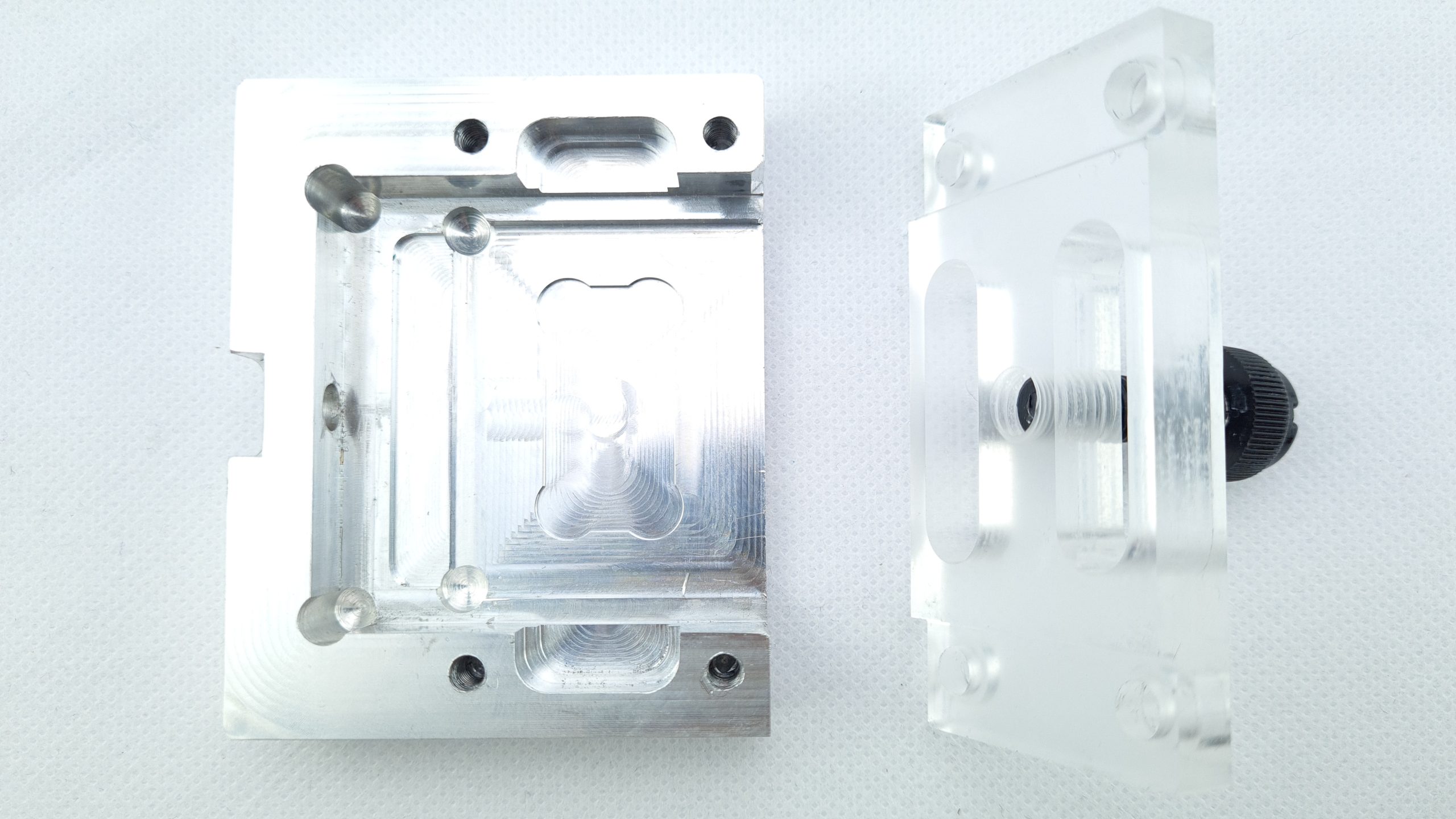
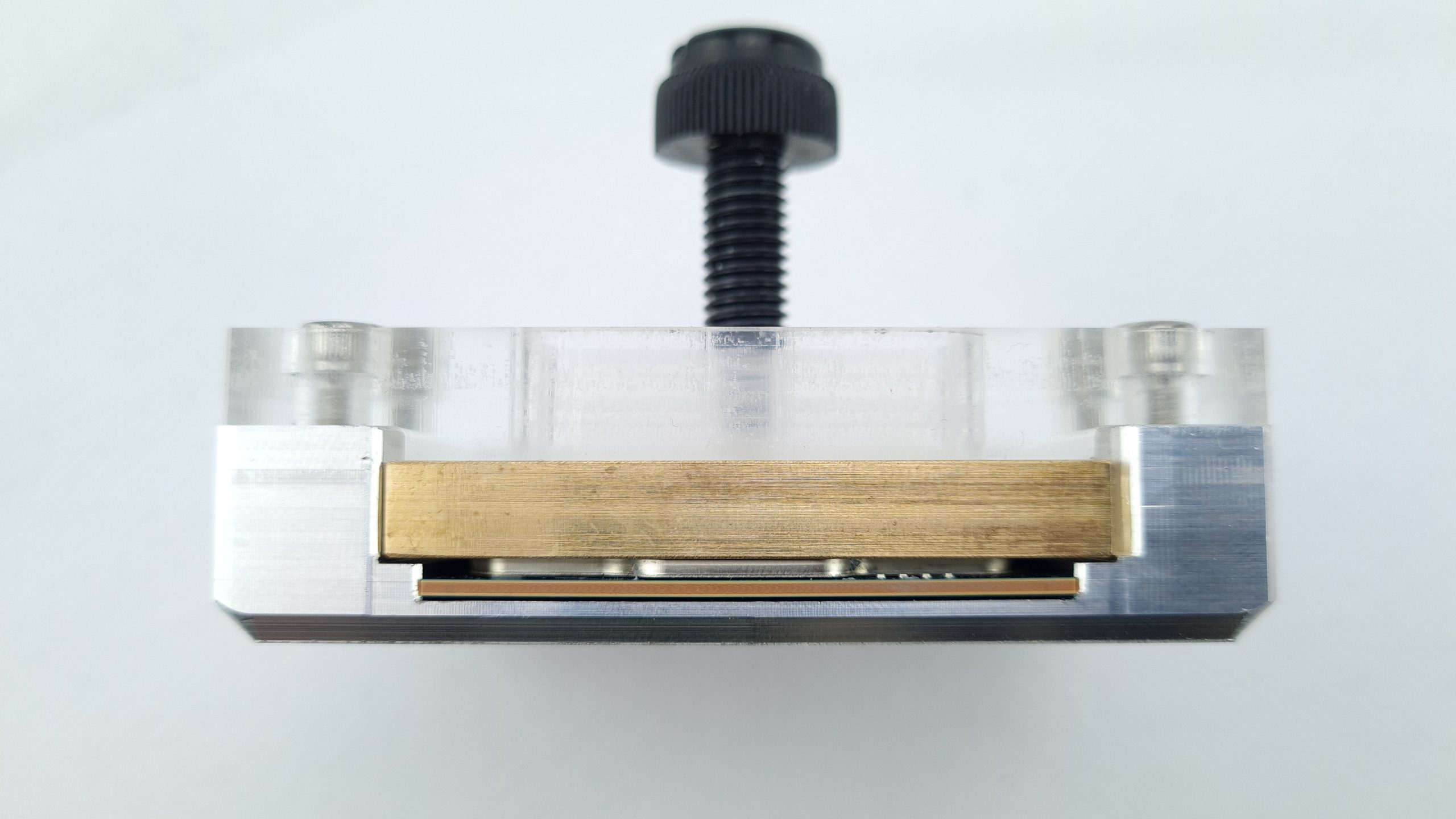
At first glance, the tool is somewhat reminiscent of a Frankenstein-like construction, with components made of aluminum, brass and acrylic, held together by four hexagon socket screws, this time M4 with 3 mm heads. A black plastic screw clamp is integrated at the top center, which can be used to fix the IHS in place if it is glued again later. 

From the side, you can see how the brass part is effectively a kind of slide in the outer aluminum part and at the same time is held at the right height by the acrylic part. Unfortunately, the manufacturing is not really 100% precise for my German understanding with about a millimeter of play on the side and half a millimeter upwards.

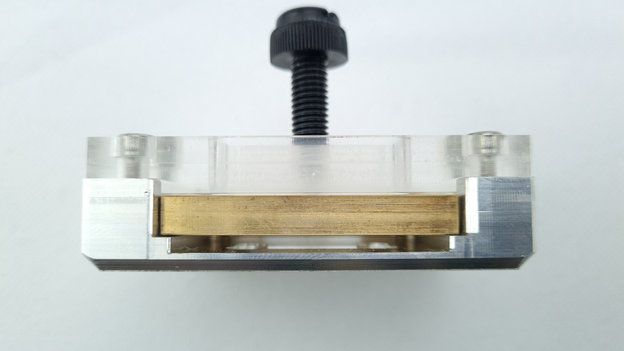
The actual shearing motion is provided by an M5 ball bearing screw with a 4 mm Allen head, which is designed to pull the slide toward it from the side of the tool.


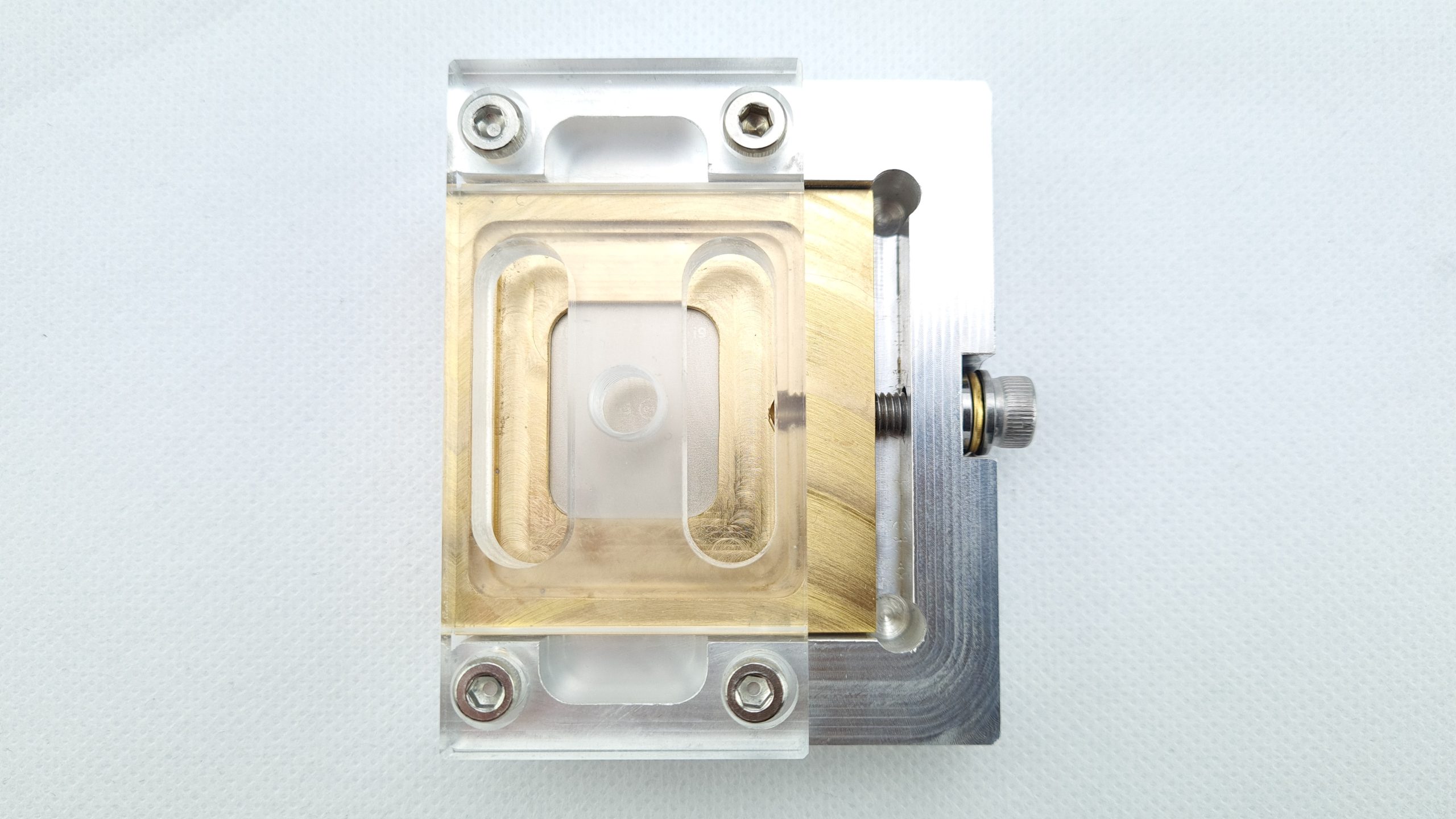
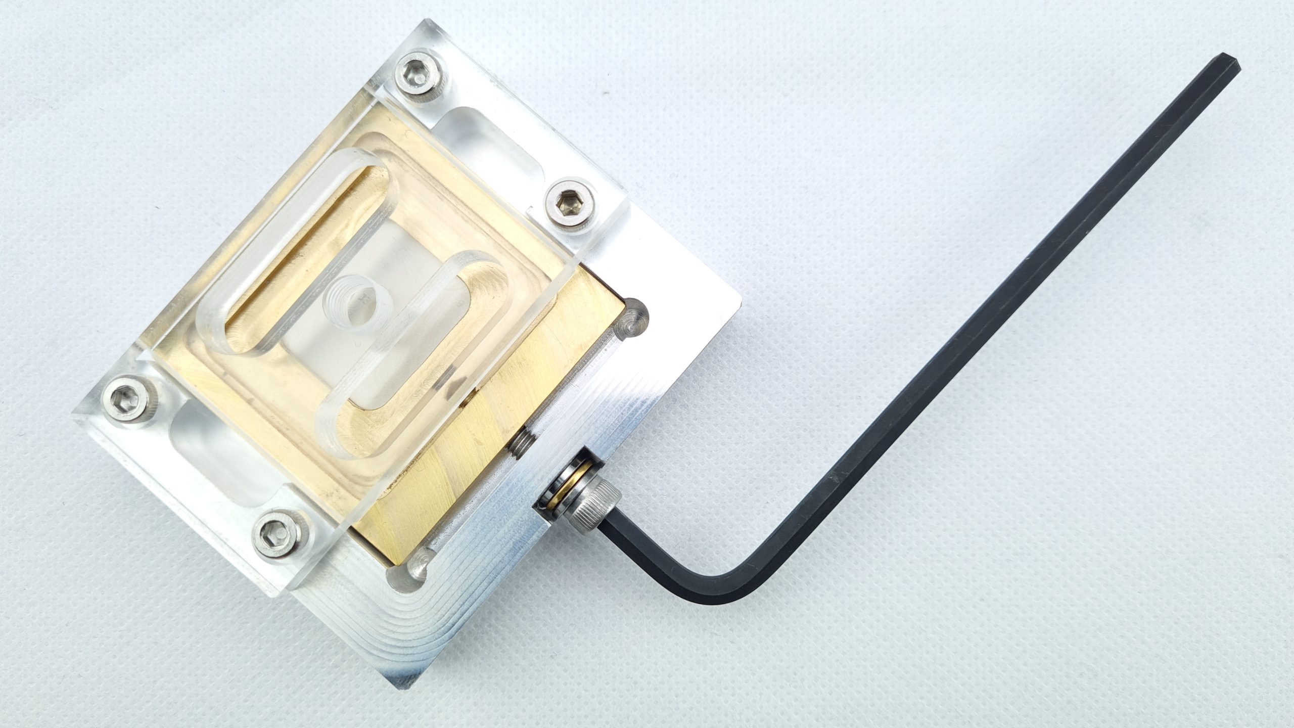
After removing the screw, the brass slide can be easily pulled out. This has a two-step milling from the top, which can be used to align the IHS for re-gluing. 

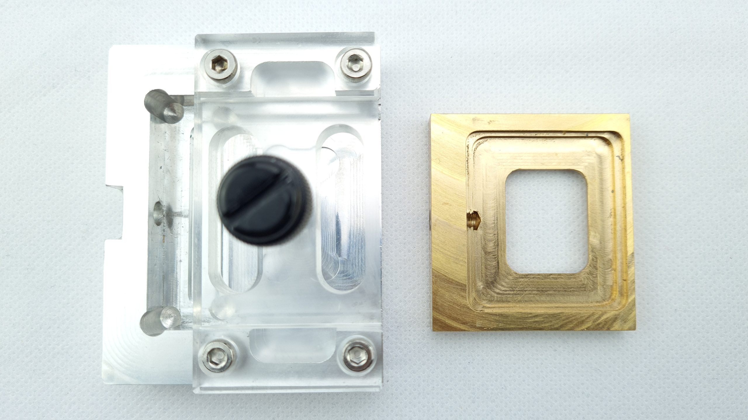
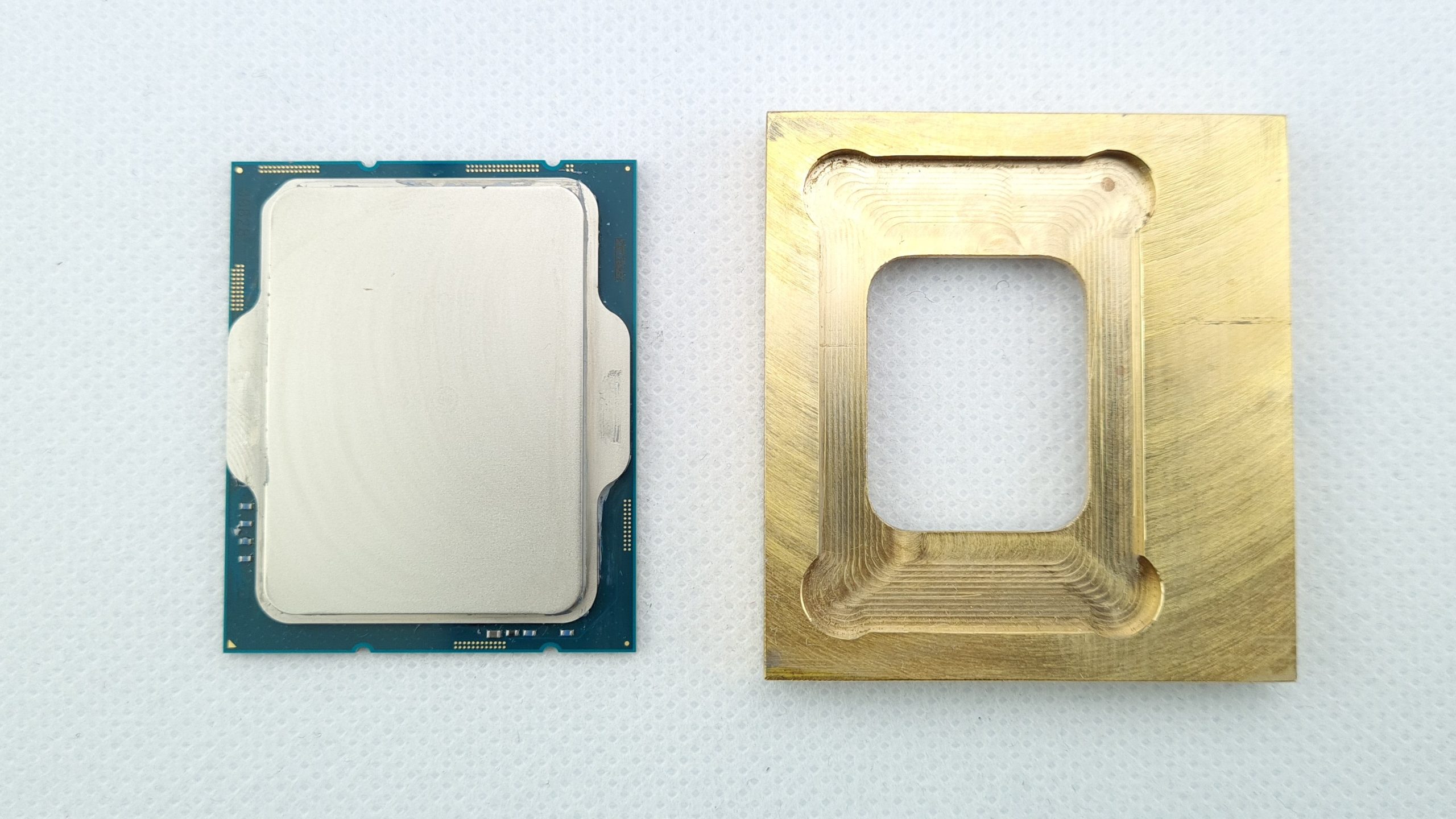
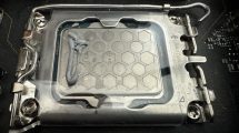
If we now remove the acrylic element, the really important milling for locking the CPU for the Delid process is revealed. First, we find the seat for the CPU with effectively the same dimensions as an LGA1700 socket. The two inner corners are drilled out, probably to prevent damage to the CPU there. Another recess is integrated in the center of the CPU seat, into which the tiny SMD components on the bottom of the CPU can protrude without contacting the tool.

Here in particular, there are still sometimes clear traces of production, chips and lubricants that should be removed beforehand. So I took the few minutes and cleaned the part once as best I could first with a brush and then 99% isopropanol. After all, nothing would be more annoying than pressing an aluminum tap into the package during delidding. Supercool Computers would do great to improve here a bit after production to avoid unnecessary hassle for customers. 

Unfortunately, there are no real instructions from the Thai manufacturers on how to use the Delid tool or water block, at least not as you would probably expect. In the above linked Youtube Livestream VOD of Clock’em Up! the manufacturer has at least shown the procedure itself, with a Thai explanation, but at least the basics like the orientation of the tool parts can be recognized. I will then try to describe the decisive subtleties as accurately as possible in the following. 

Off with your head! – Delidding

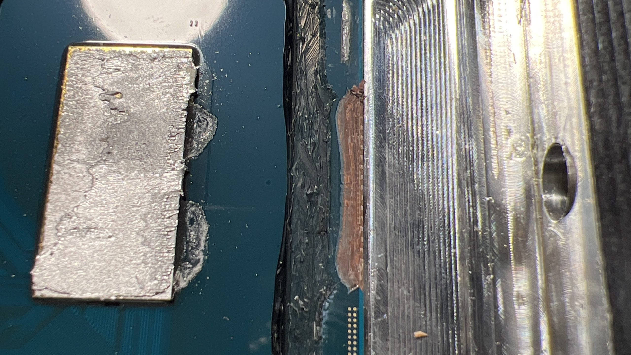
Now it’s time for the actual delidding or “beheading” of the CPU. Of course, this process cannot be reversed and will void the warranty. All of the following steps should therefore always be carried out exclusively at your own risk. Neither Intel nor Supercool Computers are liable for a dead CPU in any case. In the worst case, there doesn’t have to be any damage to the silicon die for the CPU to die. Even the smallest damage to the package or SMD components can be sufficient for this. Example:

Now this is not my first delidded CPU and so far everything always went well with me (knock on wood!), but with respect and caution one should always approach the matter nevertheless. And even then, there is always a certain remaining risk that you should be prepared for. But now I’ve scared you enough – let’s finally get started. For delidding, the side of the brass carriage with a single milling edge is used (not the one with two milling edges).

Before that, I put the CPU with its heatspreader upside down into the sled to check the fit. And indeed, the CPU fits here like a glove and almost sucks. A few thermal paste remnants from previous installation, which subsequently hung on the inner edge of the brass slide, are witness to the snug fit.

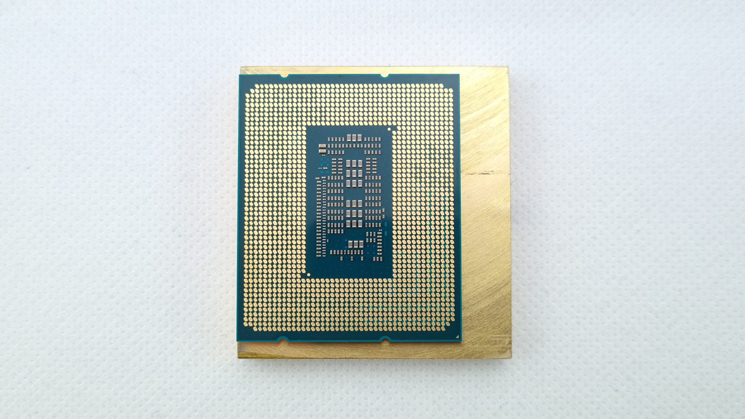
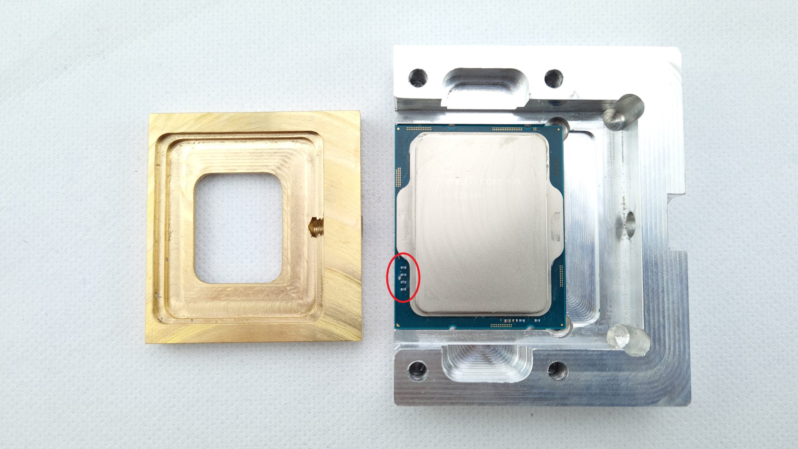
Now I’ve effectively flipped the sled and CPU once, so that the side with two edges is looking at us and the side with one edge is facing down. So we will put the parts in the aluminum part as well. But before that, it is still extremely important to pay attention to the correct orientation of the CPU. 

That’s because it also has SMD components on the front, which would shear off if positioned incorrectly! So make sure that the SMD components on the long side of the CPU are on the open side of the aluminum part. Furthermore, of course, make sure that the CPU sits correctly in its recess and has no play upwards, downwards or to the right.

Now the brass slide is simply placed on the CPU. This should now sit fairly flush with the aluminum frame on the left and have a gap on the right. The heatspreader on the package is going to be moved towards this gap later.

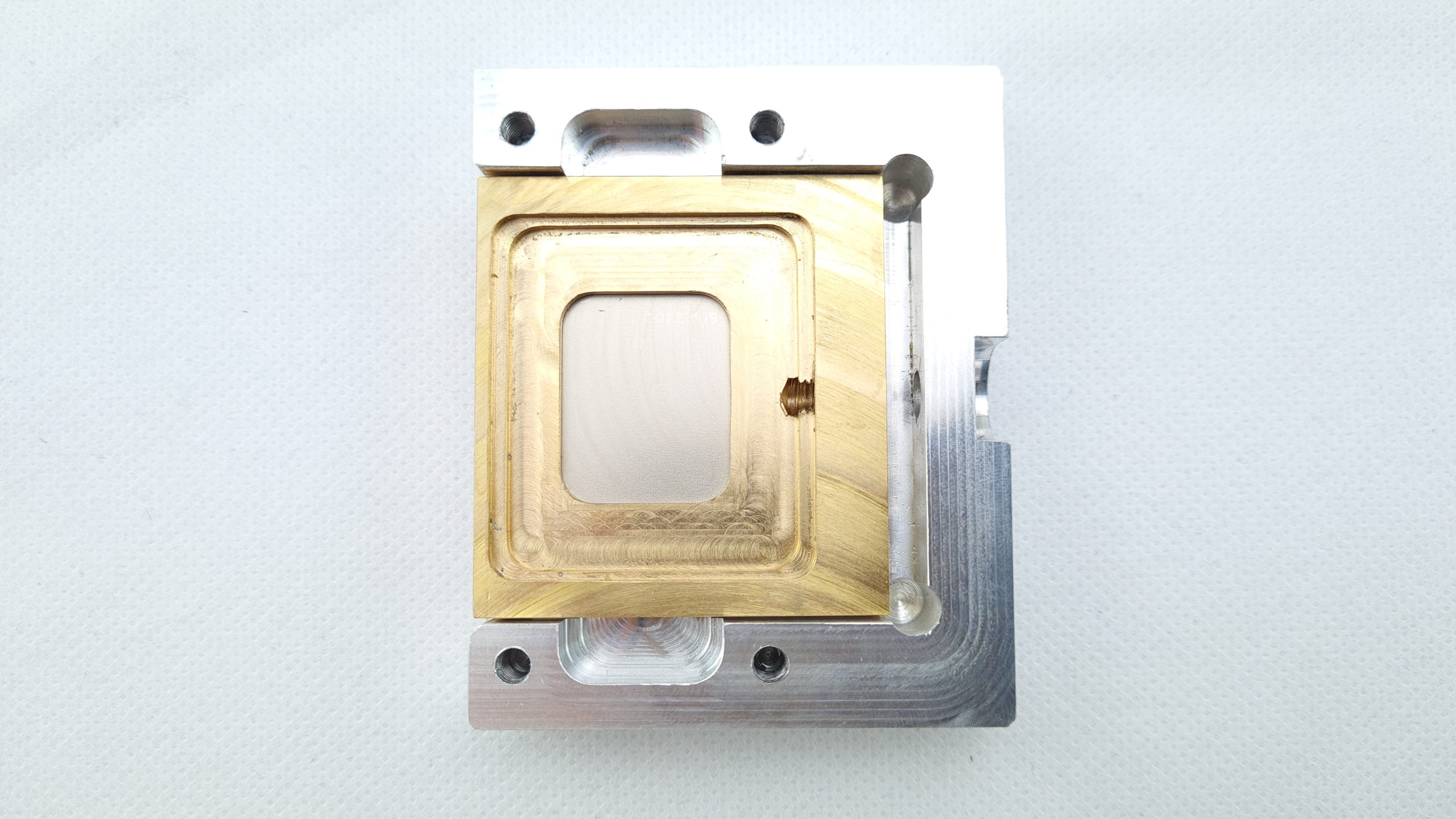
Now it is still important to re-place the acrylic lid and screw it tight. This ensures that the sled is held flat on the heatspreader and cannot stand up.

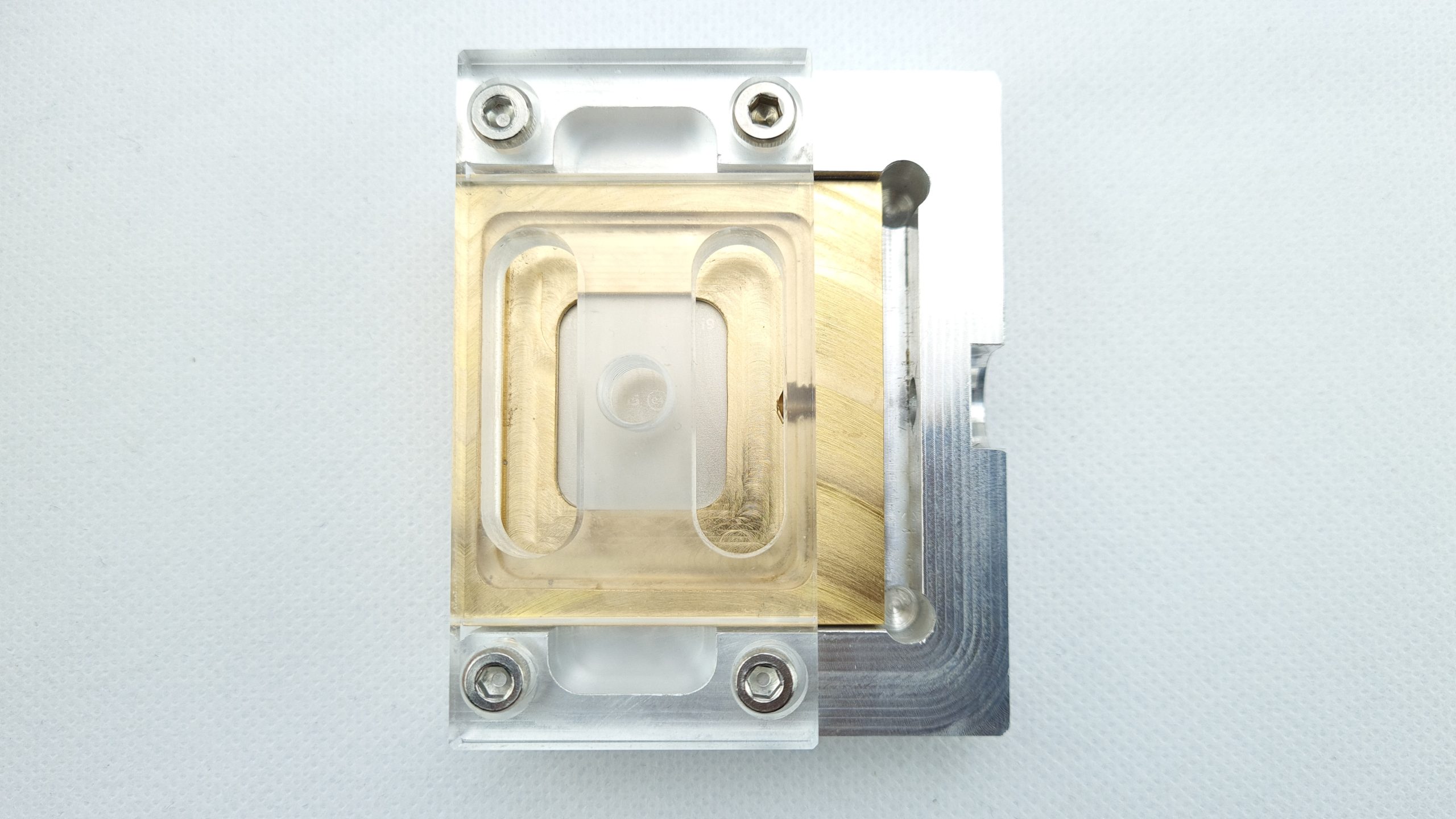
From the side, you can see how the brass slide rests exactly on the ILM nose of the heatspreader, but does not exert any pressure yet. The acrylic lid holds the aluminum, package, IHS, brass sandwich in place vertically only. Just think away the black plastic screw clamp at the top – I hadn’t unscrewed it when I took this photo.

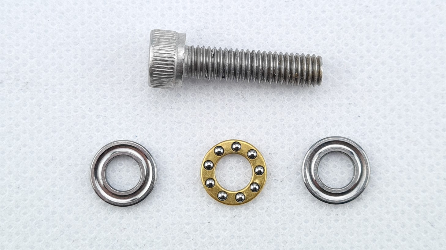
Now the only thing missing is the insertion of the large M5 screw including ball bearing and we can almost start with the delidding. Here, also pay attention to the orientation of the groved surfaces towards the ball bearing so that it functions correctly.

Now it’s time to get serious – insert the supplied 5 mm Allen key and carefully, slowly, but inevitably turn the screw vigorously until the heatspreader slowly moves on the CPU. Always check from the side and make sure that the sandwich layers just shown remain in position inside the tool. Whether the CPU survived, you can see on the next page!


Kommentar

Lade neue Kommentare

b
b_fiek

Mitglied

21 Kommentare 1 Likes

Bald sind wir wieder auf Pentium 4-Niveau.. die waren doch damals Grund für BTX-Formfaktor..

Antwort 1 Like

RedF

Urgestein

4,665 Kommentare 2,553 Likes

Inbus nicht Imbus :geek:

Antwort 4 Likes

k
krelog

Veteran

173 Kommentare 53 Likes

Danke für die Test.

Wie verhält es sich hier mit durchbiegung der "Wasserblocks"

Antwort Gefällt mir

Igor Wallossek

1

10,204 Kommentare 18,838 Likes

Bitte einigen wir uns auf Innensechskant, das wäre dann wirklich korrekt :D

Weil, im Bus tragen wir Masken... *duckundweg*

Antwort 6 Likes

RedF

Urgestein

4,665 Kommentare 2,553 Likes

Aber danke für den Artikel.
Meine letzte geköpfte CPU war glaube ein Core2Duo, die war noch nicht verlötet.

Antwort 1 Like

Denn1s

Veteran

118 Kommentare 35 Likes

Wenn schon gendern dann richtig! Sechskant:innen!

🤡

Antwort 2 Likes

Triton

Mitglied

35 Kommentare 20 Likes

Ja, darf dabei nicht fehlen, ansonsten fühlt sich 50% der Menschheit nicht angesprochen. 😁

@Igor: Wieviel Kilo hast Du bei der Aktion abgenommen? 😅

Antwort Gefällt mir

Llares

Mitglied

71 Kommentare 35 Likes

Bei so einer Aktion zuzuschauen, erzeugt bei mir die gleichen Gefühle, wie z.B. bei einer Zahnbehandlung zugegen zu sein: es stellen sich mir sämtliche Nackenhaare auf.

Antwort 3 Likes

Igor Wallossek

1

10,204 Kommentare 18,838 Likes

Der Test ist von Xaver. Da ich nicht selber ran musste, habe ich zugenommen ;)

Antwort 4 Likes

skullbringer

Veteran

306 Kommentare 328 Likes

Da wir effektiv den IHS komplett direkt mit dem Wasserblock austauschen, gibt es das Problem der nicht zueinander passenden Flächen nicht mehr. Die Bodenplatte würde ja im selben Verhältnis verbogen wie Die und Package.

Davon abgesehen habe ich die Montage des Direct-Die Blocks mit und ohne "Washermod" getestet und die Ergebnisse waren praktisch identisch. ;)

Antwort 1 Like

Alexander Brose

Moderator

819 Kommentare 574 Likes

Schöner Artikel und klasse Ergebnis, Xaver (y)

Schon irgendwie ein Bisschen bitter, dass man so einen Aufwand betreiben muss, um die CPUs optimal zu kühlen. Aber für uns "Nerds" ist das ja schon auch eine kleine Herausforderung und Teil der Faszination. Ich habe zu Sockel A Zeiten in einem Computerladen gearbeitet und gehöre somit noch zu der Generation, die ausschließlich Direct-Die Kühlung betrieben hat. Da hat man abgebrochene Ecken oder am Kühlerboden klebendes Silizium öfter mal zu sehen bekommen... gab ja auch damals schon minderwertige Wärmeleitpasten/-pads und Kevins 😁.

Grüße!

Antwort 2 Likes

RedF

Urgestein

4,665 Kommentare 2,553 Likes

Mein erster Athlon 1200 hatte auch etwas Karies an der kante, ist aber gut gelaufen. 😅

Antwort 1 Like

jo-82

Mitglied

54 Kommentare 21 Likes

Als jemand der seinen 7820X auch geköpft hat um die miese Wärmeisolationspaste die Intel da reinspritzte gegen was vernünftiges zu tauschen (hab Kryonaut genommen) begrüße ich solche Artikel. Auch wenns mit den aktuell wieder verlöteten Heatspreader eigentlich nur noch was für die OC Nerds ist.:cool:
Was mich allerdings abschreckte war der Preis den der Bauer damals für das Tool aufgerufen hat, satte 80€ sollte das Kosten... Habs dann ein Jahr später für nen 10er aus China bekommen.
@skullbringer: Darf man fragen was das Tool in dem Fall einzeln kostet?

Antwort Gefällt mir

T
Tombal

Veteran

109 Kommentare 28 Likes

Ich frage mich gerade, ob es nicht schonender für die CPU wäre, den IHS auf 150°C zu erhitzen, bis das Indium-Lot schmilzt, und einfach auszulöten. Der Kleber am Rand dürfte bei diesen Temperaturen auch schon etwas weicher werden und schnell nachgeben. Das halte ich für besser, als mit brachialer Gewalt den IHS abzuscheren. Und warum lötet man den neuen Kühlblock nicht einfach wieder drauf, das wäre doch besser als eine Wärmeleitpaste. 150°C sind für Halbleiter eigentlich kein Problem, besonders dann nicht, wenn sie stromlos sind.

Antwort 1 Like

ArcusX

Urgestein

867 Kommentare 501 Likes

War auch meine erste Idee. Backofen z.B. Das Silikon ist wahrscheinlich sogar bis mehr als 150° Hitzefest und dürfte nicht verbrennen.

Antwort Gefällt mir

geist4711

Veteran

274 Kommentare 127 Likes

eigentlich eine gute idee, ABER:
überlege dir mal wie du den wasserkühlblock auf die 150°C bringen willst,
damit der sauber angelötet wird ;-)
und, der hat ja kunststoff mit dran, bis wieviel grad hält das aus?

Antwort Gefällt mir

RedF

Urgestein

4,665 Kommentare 2,553 Likes

Heißluft Föhn, kunststoff musst natürlich vorher abmachen.

Antwort Gefällt mir

Martin Gut

Urgestein

7,785 Kommentare 3,577 Likes

Leider nein. Bei der aktuellen Generation ist es soweit mir bekannt nicht schlecht gelöst. Als Intel bei der 9. Generation mit den verlöten wieder angefangen hat, war es aber auch nicht so toll wie angepriesen. Weil der Chip grösser war, hat man die Dicke des Silizium verdoppelt und dann 0.3 mm Lot darauf gebracht. Durch so dicke Schichten war der 9900K teilweise schlechter als die Generation davor mit Wärmeleitpaste. Dazu waren manche Prozessoren über 20 Grad wärmer als andere gleiche Prozessoren. Wenn man Pech hatte, war ein 9900K somit nicht vernünftig kühlbar. Schlecht verlötet ist auch nicht besser als die miserable Paste. Paste kann man wenigstens problemlos dünn auftragen. Naja, Intel schafft nicht mal das. Bei den neueren Generationen hat man aber glücklicherweise die Schichten dünner gemacht.

Man könnte die CPU auch im Backofen auf etwa 120 Grad aufwärmen und dann mit den Delide-Tool köpfen. Wenn Silikon und Lot warm sind, geht es schon leichter.

Verlöten einer so grossen Fläche ist sehr schwierig. Die Prozessorhersteller tragen auf den Heatspreader meist mehrere Schichten auf und vergolden die Fläche. Ohne das würde man das Lot nicht zum halten bringen. Mit einem Heissluftföhn kann man die Temperatur nicht so genau kontrollieren, dass das Lot auf der ganzen Fläche flüssig ist aber sonst nichts so heiss wird, dass es Schaden nehmen kann. Man weiss ja auch nicht, mit welcher Temperatur die CPU und die anderen Bauteile auf die Platine gelötet wurden. Man müsste ja unter dieser Temperatur, die man nicht kennt, bleiben. Am ehesten müsste man Niedrigtemperatur-Lotpaste dünn auftragen und dann im Backofen so weit erhitzen bis der Kühler verlötet ist.

Vor den Auftragen von Flüssigmetall hätte ich die Bauteile rund herum mit irgend einem Lack abgedeckt.

Antwort 3 Likes

Klicke zum Ausklappem
RedF

Urgestein

4,665 Kommentare 2,553 Likes

Damit müsste das doch gehen

View image at the forums

Antwort Gefällt mir

Danke für die Spende


Du fandest, der Beitrag war interessant und möchtest uns unterstützen? Klasse!

Hier erfährst Du, wie: Hier spenden.

Hier kannst Du per PayPal spenden.

About the author

Xaver Amberger (skullbringer)

Werbung

Werbung