


Where the too high voltage comes from – the TL431 in wrong wiring
Admittedly, errors cannot be ruled out in complex circuits. However, what you see when you look at the TL431's only 3 pins is actually hard to believe. This is a trivial circuit, which has been known for years and can be found in many power supplies, charge controllers, etc. The same is true for the power supply. It is unlikely that such experienced engineers would make such a serious mistake here – but let's take it one step at a time. If you trace the voltage from the shunts at the RT8802A, you end up after a short way at the TL431, which is supposed to provide the 5 volts operating voltage for the RT8802A.
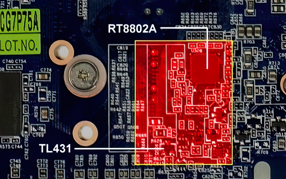
We first checked a GTX 660 Ti that uses the same circuitry of RT8802A and TL431 and operates with correct voltage (Gigabyte GTX 660 Ti Windforce 2X):
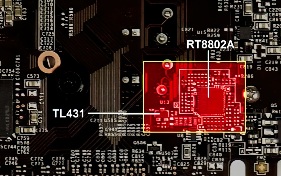
Now we compare this picture with the one of the board of our MSI card:
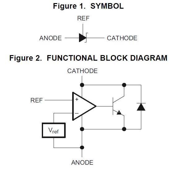
Let us now turn our attention more closely to the TL431 and its 3 terminals, consisting of anode, cathode and the terminal for the reference voltage, which decides the output voltage to be regulated:
Next, we use the TL431 data sheet and compare the connections in the photo with the block diagram:
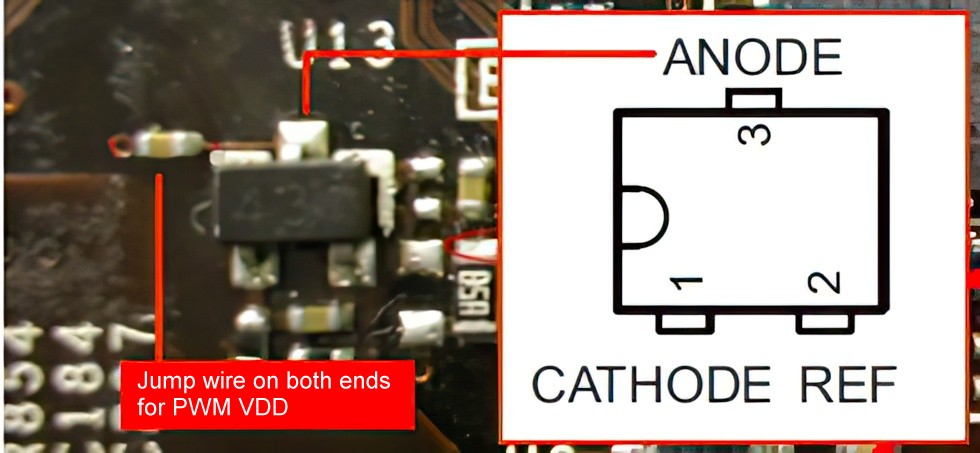
We can see very clearly the location of the anode in the schematic and now take the next step by picking out the necessary circuitry:
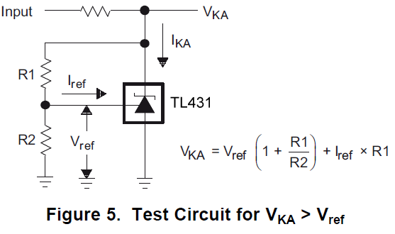
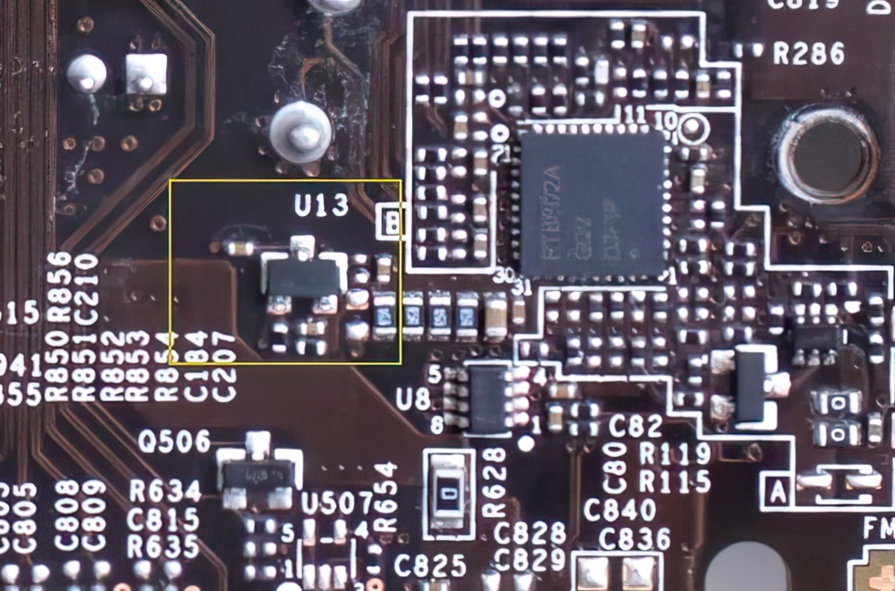
You can see very clearly that the already mentioned anode has to be connected to the ground. This is self-evident and also absolutely necessary for the regulation of the voltage. But what do we find on the circuit board? In the upper photo you can see another component to the left of the anode, which was inserted between the anode and ground and even completely separates the two in terms of DC voltage, because it is a capacitor with low capacitance. Even a resistor would have no place at this point, the anode belongs in such a circuit directly connected to ground. However, what was really wired is then shown in the circuit diagram like this:
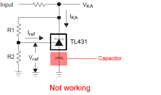
By inserting a valueless and ineffective capacitor, the outer appearance is preserved, but the function of the control loop is completely overridden, and the already described overvoltage occurs at the RT8802A. The other components R1 and R2, which are voltage dividers at the center tap and provide the control voltage (reference), are also exactly dimensioned on this PCB. If you bypass the capacitor, the TL431 works again and there are exactly 5.0 volts at the RT8802A, no matter if the power supply delivers 11.9 or 12.1 volts! Without a ground connection, however, the whole thing only functions as a simple voltage divider and does not provide a constant output voltage, but one that is much too high and also fluctuates analogously to the values on the 12-volt rail. Accident or coincidence? Based on the circumstances, it really takes an extreme amount of good will and goodwill to believe this in the end.
Family disease? The GTX 670 has this "error" as well
If we put the pictures of the almost identical boards next to each other, we can see the identical misassembly in the form of the capacitor to the left of the TL431's anode (U13) on the MSI GTX 670 TwinFrozr as well:
Interim summary
It is probably rather unlikely that a circuit error really crept in here, which moreover remained undiscovered by the manufacturer itself for such a long time. The GTX 680 does not have this absolutely nonsensical and ineffective circuitry (even though its PCB is different), and the GTX 660 (Non-Ti) does not either.


20 Antworten
Kommentar
Lade neue Kommentare
Urgestein
Urgestein
Urgestein
Urgestein
1
Urgestein
Mitglied
Mitglied
Urgestein
Urgestein
Urgestein
Urgestein
Mitglied
Mitglied
Veteran
Urgestein
Veteran
Urgestein
Alle Kommentare lesen unter igor´sLAB Community →