


First measurements on the card
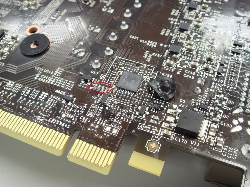
In the following picture, low impedance resistors ("shunts") can be seen in the red circle, which are located in the voltage supply to the voltage regulator (Richtek RT8802A). While "starcraftgod" from the UK forum of Tom's Hardware could measure 8.9 volts at this point after changing the power supply, this value rose up to 9.3 volts in our measurements (depending on the power supply)!
The RT8802A and the voltage cheat
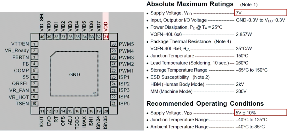
If you now also know that the actual PWM voltage at this measuring point only has to be 5 volts, then the alarm bells should be ringing at this point at the latest. We were also able to find out the cause of this extreme tension, but more about that at the appropriate place. Pin 31 is also the end of the trace that leads to the shunts where the measurements were made:
Military class or not, it is logically not advisable to operate components outside the specifications in this way. With up to 88% overvoltage, this component is guaranteed to be out of what is called the green zone. We have confronted MSI with exactly these values and would like to insert the relevant part of the answer from MSI headquarters here in a quote in advance:
Since MSI designs its customized products with overclocking in mind from the start, we give these cards an extra performance reserve from the factory because we expect enthusiasts to overclock them. Because of this design decision and the higher quality of the components, we are able to add more power to the boards. This enables a higher GPU boost level, which we can also maintain for longer without shortening the graphics card's life expectancy or its warranty period. In case of problems, customers can contact MSI at any time within the 3-year warranty period.
Let's also let the manufacturer of this chip have its say at this point, who already writes the following in the specs of the chip:
It's nice that MSI offers a 3-year warranty for this card. However, it is much more remarkable that Richtek already doesn't want to guarantee the functionality of the chip for voltages above 5.5 volts (which also includes exact curve curves of the control circuits) and even warns of the final destruction above 7 volts.
The RT8802A and the result of overvoltage: continuous boost
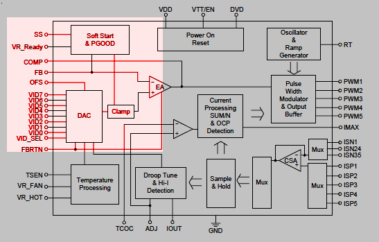
But what exactly makes this chip so interesting, and what can ultimately make a manufacturer take such a risk in the first place? Nvidia specifies certain framework conditions for the operation of each of the graphics chips, which primarily include the voltages used. Furthermore, we already know about drooping in CPUs, where the voltage is lowered under load in order to stay within the TDP limits. But why the RT8802A of all things? This rather simple voltage regulator is only effectively hard-wired for a certain GPU core voltage via the respective pin connection; it also doesn't have any monitor function or the possibility of a software-based voltage regulation. The whole thing then looks like this:
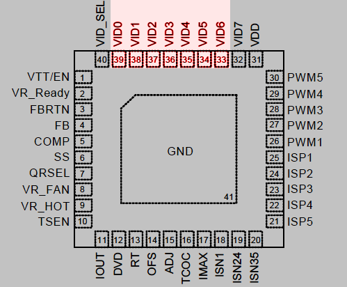
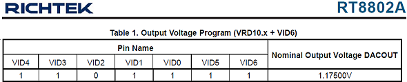
By presetting the pins, a voltage of 1.175 volts is fixed. Under load, the chip then regulates this voltage down, in the normal case this would still be approx. 1.165 volts. So everything looks perfect on the outside. Even for Nvidia, who ultimately watch over the specification and execution of the board partner cards. If the RT8802A is operated with the specified 5 volts, then exactly this voltage curve is obtained. But what happens at such extreme operating voltages?
On the one hand, a 20 mV(!) higher voltage of 1.195 V can be measured, whereby the curve (load line calibration) of the load-induced voltage drop (droop) also no longer corresponds to the specifications! The result is always increased voltage values at the GPU (which, however, cannot be read and verified without direct access to the PCB) and an almost constant continuous boost that only stutters under extreme load (see clock rates on the previous page). Since this circuit can (and does) do a lot more, this is exactly where the boost issue and the boot issue meet again:
Thus, power supplies whose voltage is already a bit above 12 volts on the respective 12 volt rail (but still within the ATX specifications) can cause the already described startup problems, because above approx. 9.3 volts at the chip's VDD input is the end of the fun. The power supply receives no or wrong information and does not switch on at all (Power Good).
Interim summary
MSI intentionally uses a much too high operating voltage for one of the most important circuits on the graphics card to be able to supply a higher voltage to the GPU on the one hand and to have to lower it less under load (droop) on the other hand. The specifications from Richtek and the statement about the durability of the control circuit are to be taken seriously in any case. As a side effect, a disturbed power-good signal occurs which, depending on the power supply, may prevent the computer from starting.


20 Antworten
Kommentar
Lade neue Kommentare
Urgestein
Urgestein
Urgestein
Urgestein
1
Urgestein
Mitglied
Mitglied
Urgestein
Urgestein
Urgestein
Urgestein
Mitglied
Mitglied
Veteran
Urgestein
Veteran
Urgestein
Alle Kommentare lesen unter igor´sLAB Community →