


Now let’s get to the electrical side of the story. The complete amplifier unit of the active speaker sits angled on a mounting plate, which carries all inputs and outputs, as well as the controls and is very firmly screwed to the body. The individual cables are routed to the board via a short path or are avoided by having the board carry already soldered sockets. The IEC socket and the power switch are sealed with hot glue on the side once again, while the ground potential of the Schuko socket leads directly to the metal plate and the conductor was screwed there. This is important to know insofar as in the worst case one must carry out a galvanic ground separation in the analog RCA range here, if it should come to a ground hum. Or you can use the balanced inputs or TOSLINK.
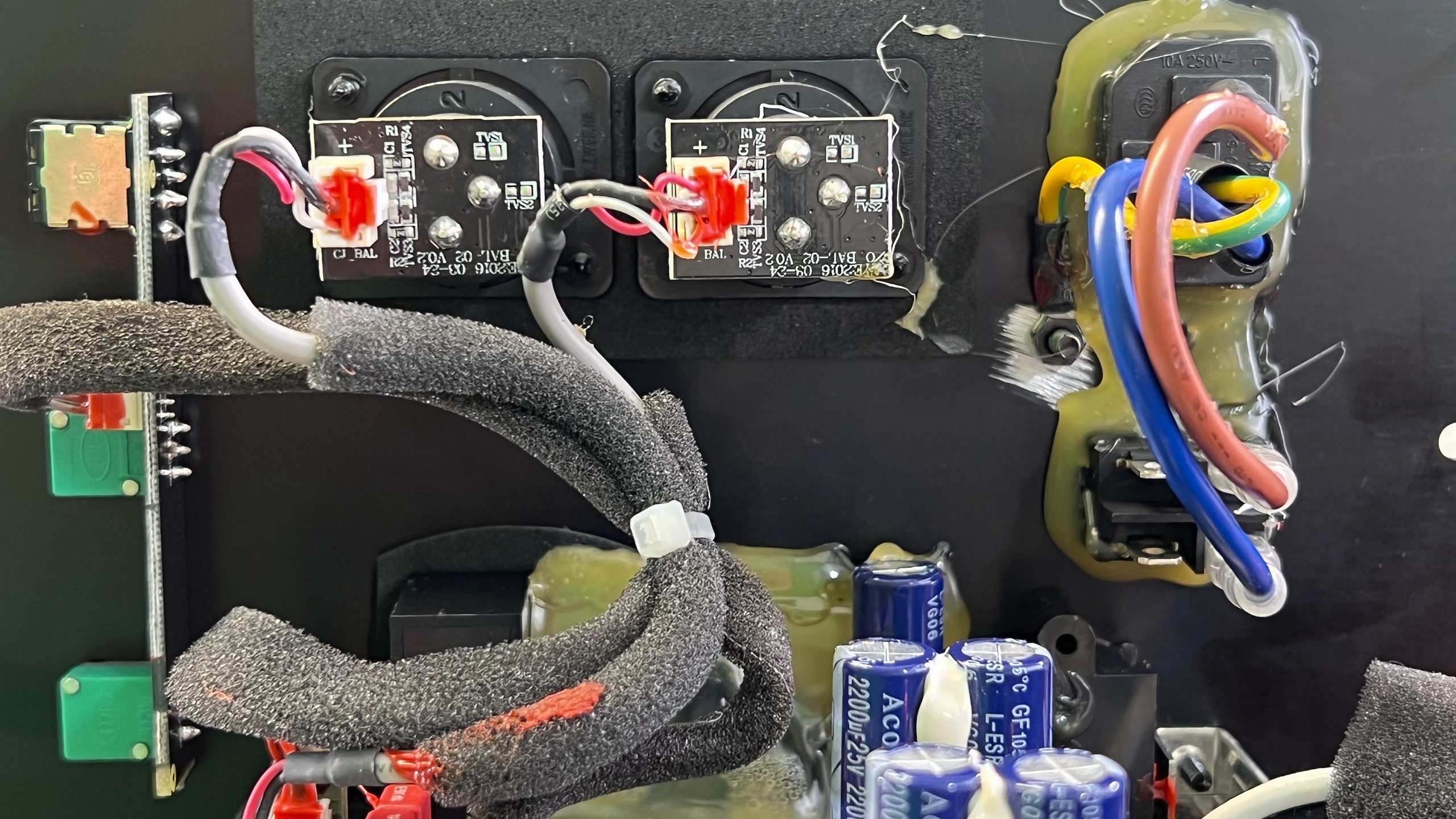
The PCB comes from Shenzhen Shengchenghui Circuit Science Technologies Co Ltd and makes a pretty solid impression. The soldering quality of the assembled board is visually completely acceptable, there are hardly any visible flux residues. The use of hot glue is limited to the necessary, neuralgic points, nothing more. While the feeds to the IR receiver and the chassis are removable, the switching power supply, which is screwed to the base, is firmly soldered. If you want to remove the board completely, you also have to remove the power supply, which proves to be quite cumbersome. But the contacts are at least absolutely safe, which is the main thing.
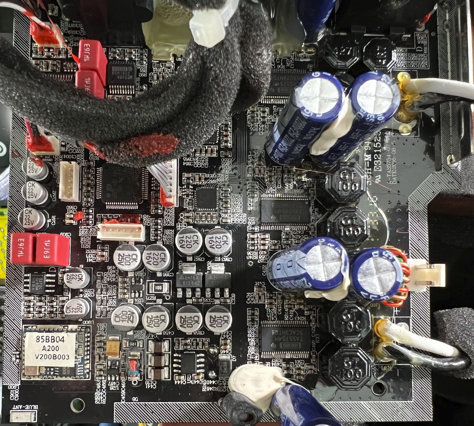
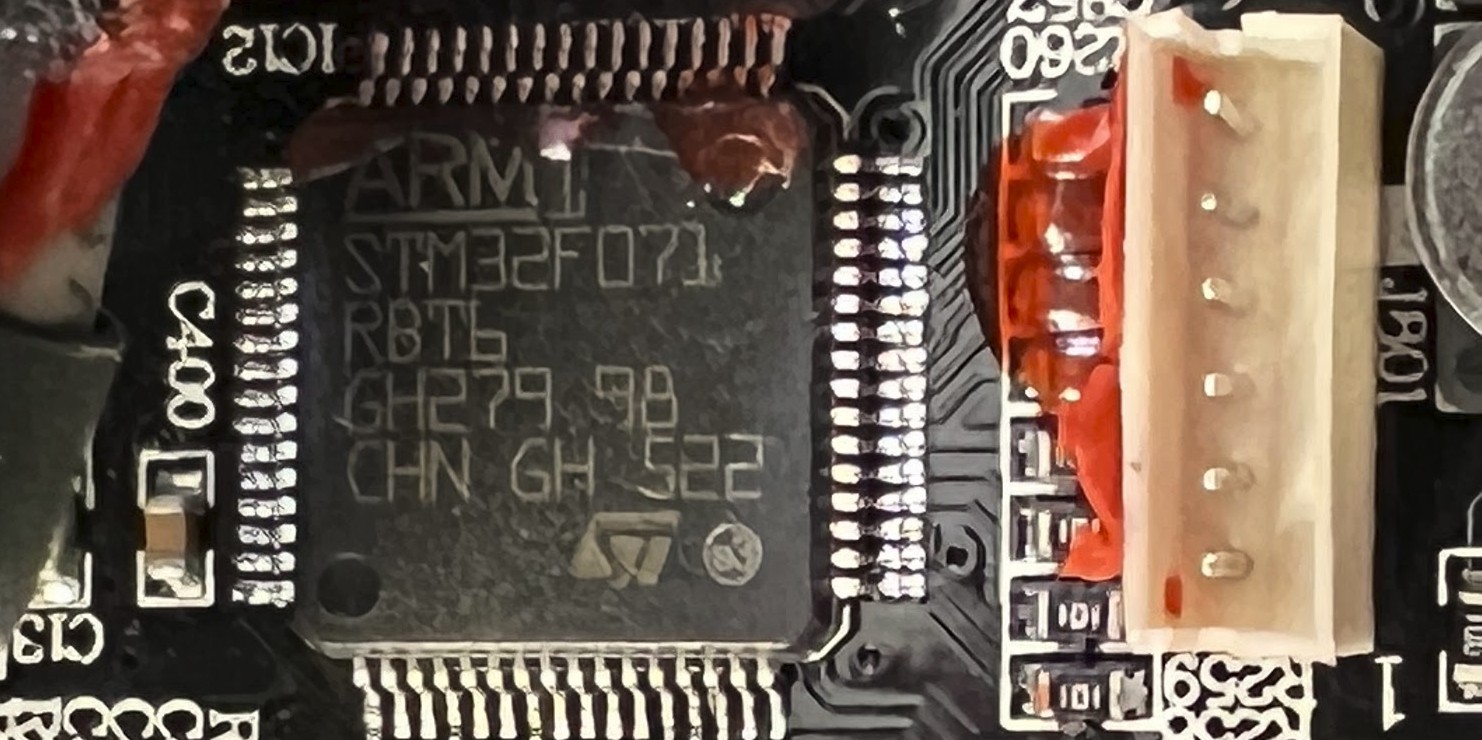
Now let’s get to the actual circuitry, where Edifier naturally builds on tried and true. For overall frequency division and dynamics management, the Airpulse A200 uses ST Microelectronics’ rather inexpensive STM32F071 as its DSP chip. The active crossover, dynamics and power management are already known from older models in this or similar form. This DSP replaces the analog frequency separation on the output side and can thus also drive separate amplifier stages for the mid/bass and treble. The chip is a normal ARM Cortex-M0 access line MCU with 128 Kbytes flash memory and 48 MHz clock for the CPU and CEC functions.
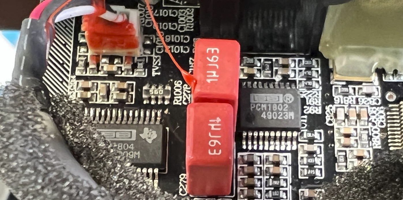
As for the unbalanced analog RCA signal input, the A200s use the PCM1802 ADC to perform A/D conversion at 24 bit/192 kHz after receiving the analog signal.
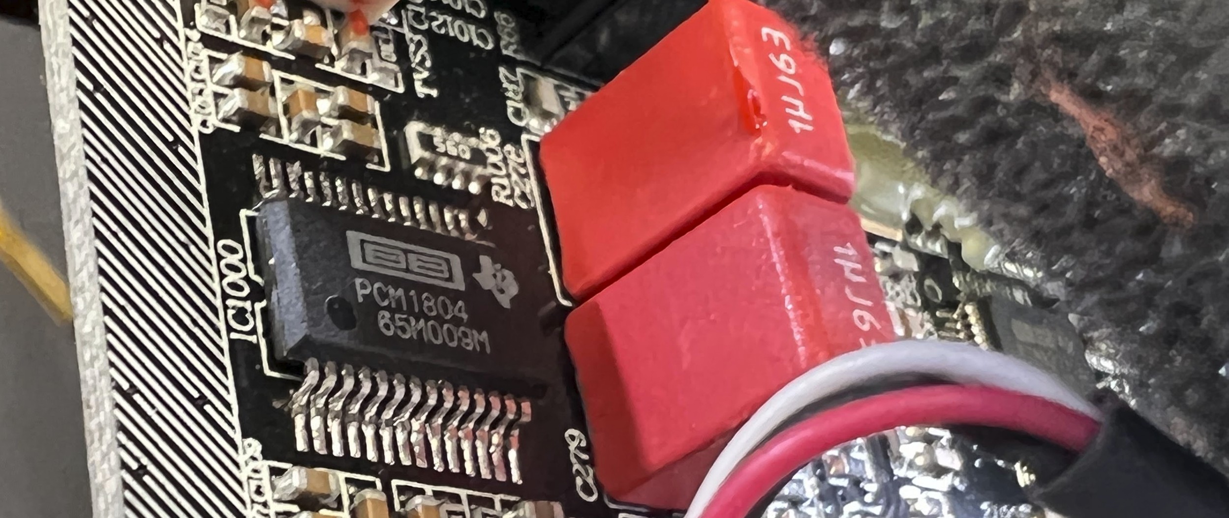
The balanced input is equipped with a PCM1804 ADC chip. The reason for this is that the PCM1804 can support an analog differential signal input. That is, it becomes exactly “symmetrical”. It supports AD conversion up to 24 bit/192k Hz and has a dynamic range of 112 dB.
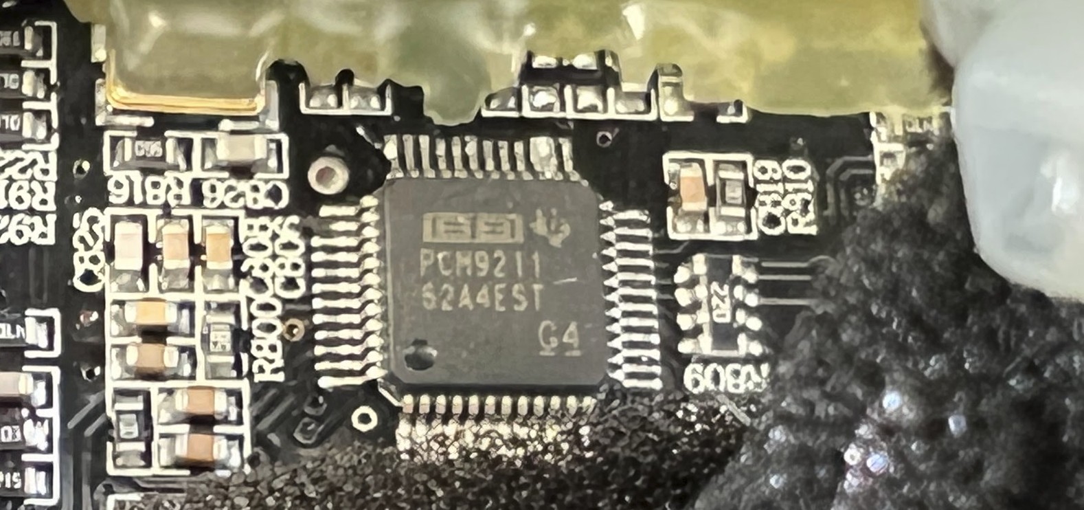
For the digital signal input, Edifier uses the PCM9211. The chip itself has full ADC functionality and was also used in earlier R-series products. The A200s also offer a coaxial and a fiber SPDIF signal input. This also supports up to 24 bit/192 kHz. Furthermore, Edifier uses the CSR8645 Bluetooth receiver chip. This supports APT-X encoding and theoretically offers better sound quality than many a competitor.
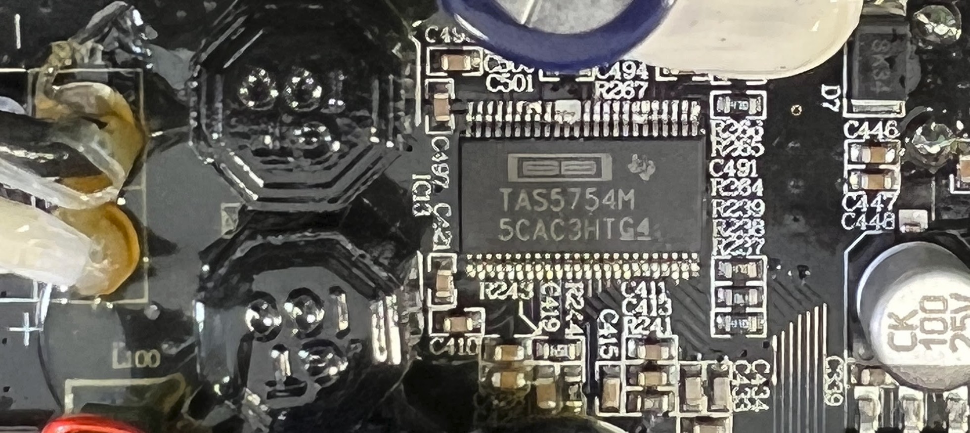
In the digital power amplifier section, the A200s use no less than three TAS5754s as digital power amplifiers. This is a highly integrated Class D amplifier with a digital signal input of 192 kHz and a PWM frequency of 768 kHz. While two of the chips each provide 2 x 55 watts RMS in a bridge circuit for the two mid-woofers, the third chip is operated in stereo mode with two channels each and 10 watts RMS per channel for the tweeters. Here the impedance is significantly higher.
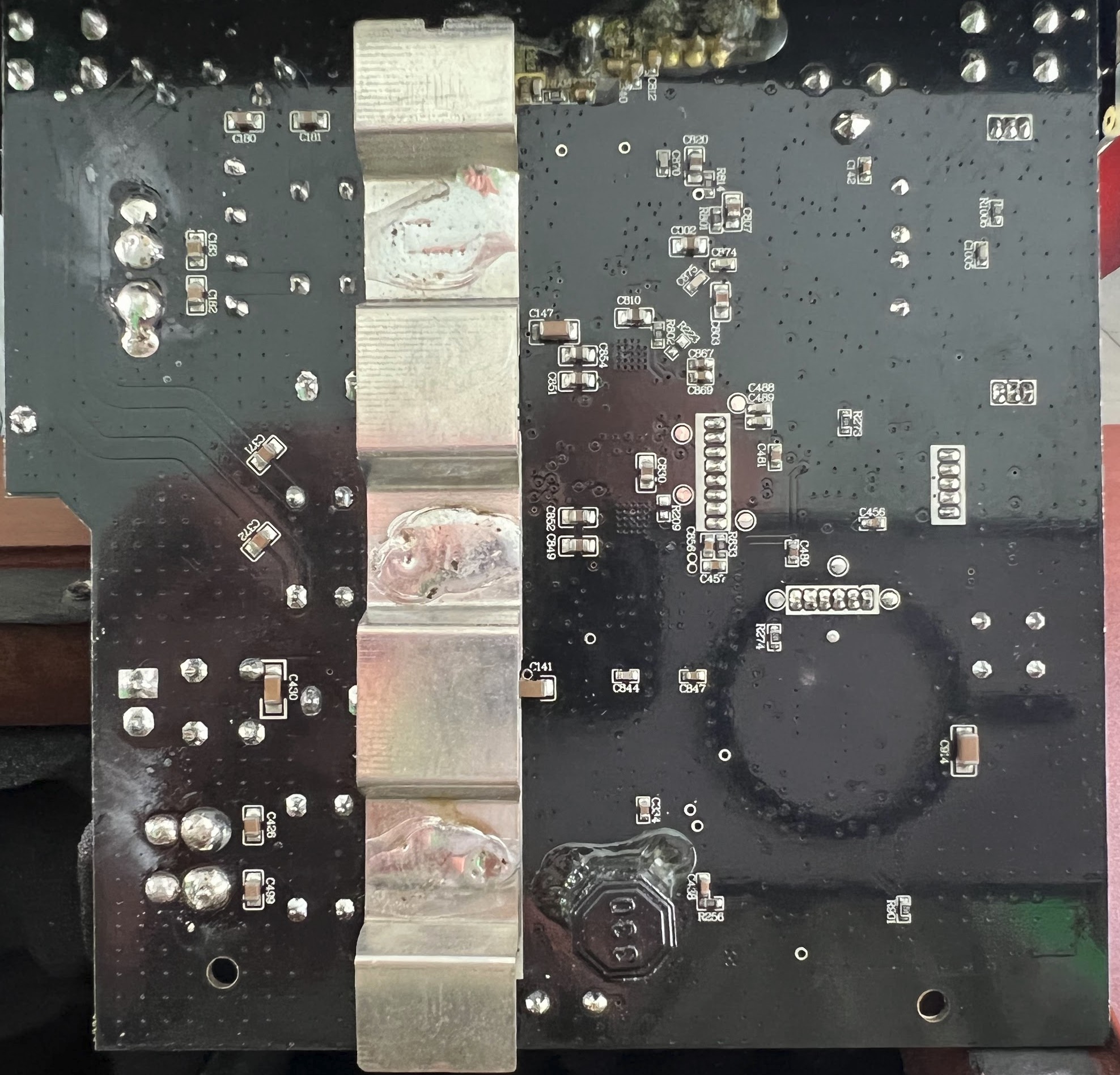
The three power amplifier chips are cooled by a rear-soldered, tinned metal strip. This is quite sufficient in practice. We can also see that some of the connections, such as the operating voltage, were soldered on manually. Not really nice to look at, but functional.


18 Antworten
Kommentar
Lade neue Kommentare
Urgestein
1
Urgestein
1
Urgestein
Veteran
Veteran
Urgestein
Moderator
1
Mitglied
Veteran
1
Urgestein
1
Urgestein
Mitglied
Mitglied
Alle Kommentare lesen unter igor´sLAB Community →