


So, now it gets interesting! I was first afraid that the massive heatspreader would distribute everything in such a way that you wouldn’t see any differences, but that wasn’t the case, thank God. Preparing with the Ryzen 7 7700X for my radiometric video, which I shot at 32 FPS, was a bit tricky, though. Thanks to PROCHOT, the CPU will not burn up, but how do you “film” the process in such a way that reliable measured values are generated and the CPU does not suffer permanent damage?
The problem is the heatspreader: it is a metallic surface with a very low emissivity. You can’t really measure that with an infrared camera. Therefore, I put a very thin sheet of phase change material on it and brought the whole thing to burn-in at about 56 °C. The material melts, runs and then hardens completely. One obtains an ultra-thin, very homogeneous and equally strong layer with a known emissivity, which I previously determined on my simple blackbody emitter by comparative measurement.
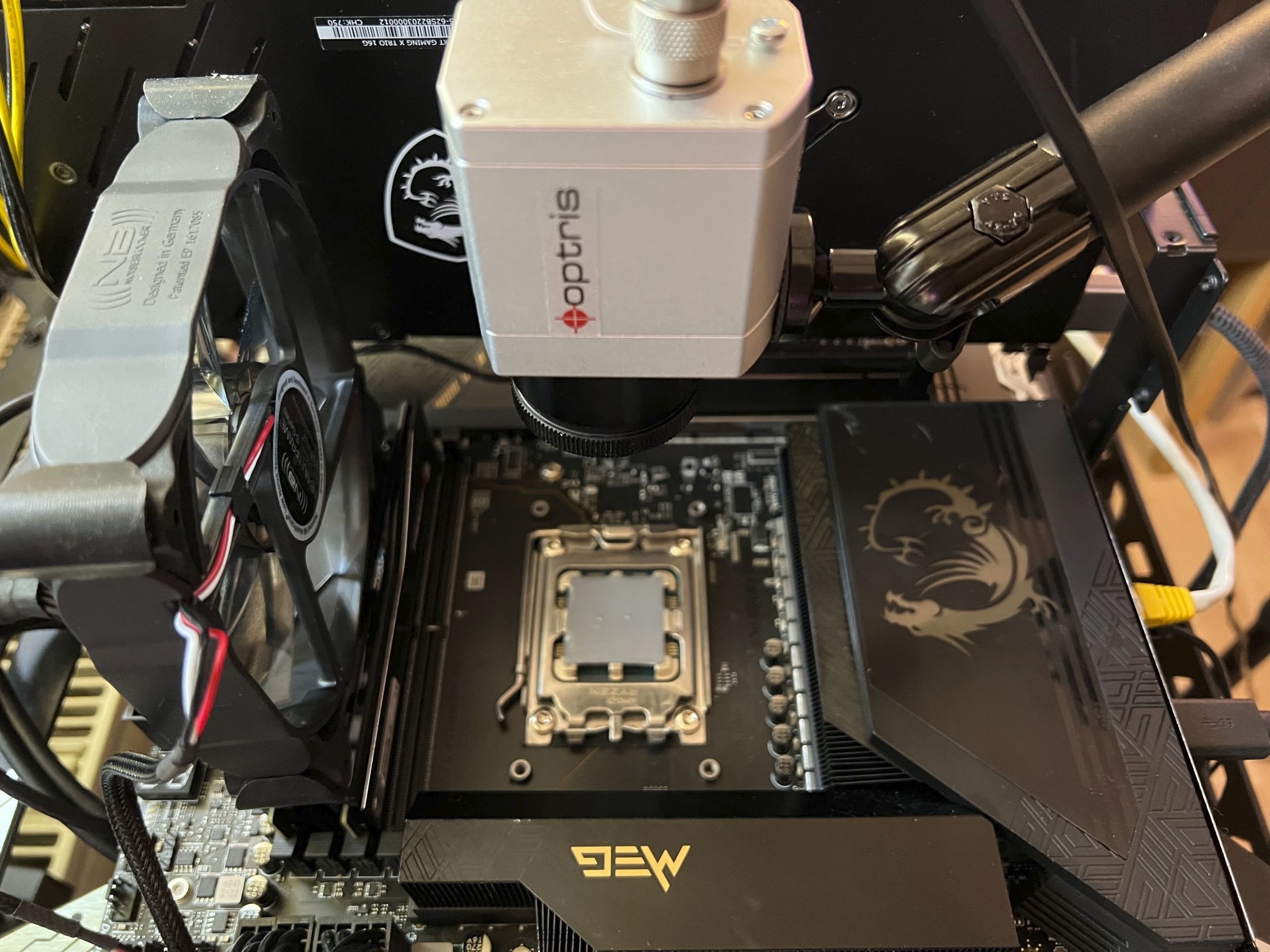
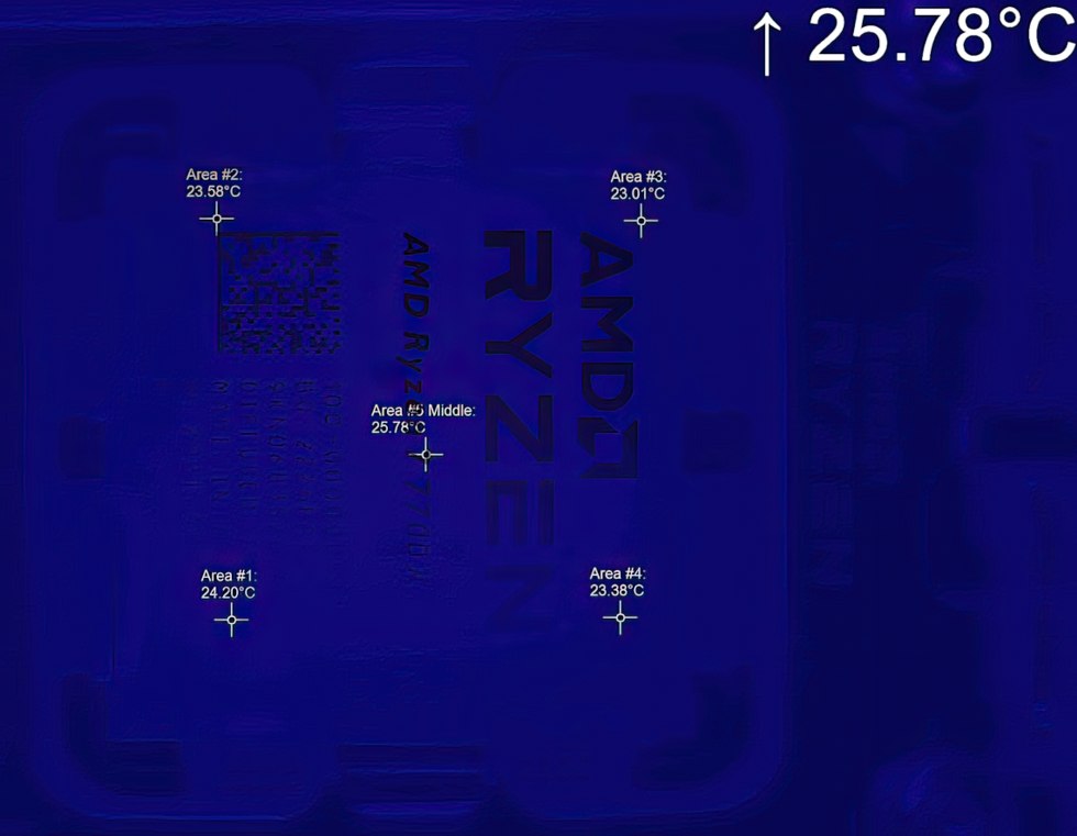
I now give this value to each of the five measuring points, having already placed them after an initial measurement (automatic hotspot) so that I include the hottest spot in each case. Only after that the fun was recorded by video. I have linked the final video here at the end of course, but I would also like to show you a few stills in advance and explain what you then have to pay attention to in the video. This is a special superposition where I additionally superimpose the radiometrically captured data and frames by means of superposition first with the original heatspreader and then with a graphic of the delidded CPU so that you can also see exactly what is inside where. Let’s first start with the startup and the cold CPU.
A few seconds later, you can already see the warming chiplet at the bottom left, the IOD is a bit cooler. However, you can also see that the IHS still distributes the waste heat quite well, even though there is a delta of more than 8 Kelvin from the hottest to the coldest measurement. The IOP here is only just under 2 Kelvin hotter,
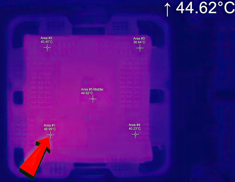
With increasing time and further warming, you can see very well how the temperatures equalize slightly. Chiplet and IOD are about the same temperature, and there is still plenty of 6 Kelvin difference toward the cool corner.
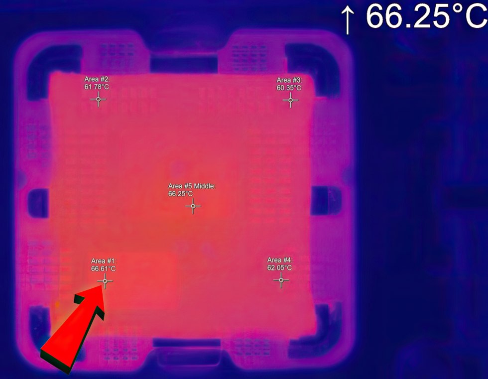
It gets even warmer and you can already see on the PCB where the most waste heat is currently generated, namely at the bottom left of the single chiplet. The IHS distributes the whole thing quite well IOD as well as chiplet are still in something equally hot.
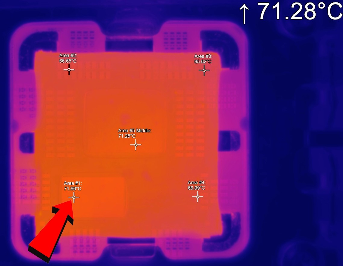
A few seconds and degrees later, the hottest spot is reversed and the hotspot is more in the center. The corners are now also warm and the temperature difference drops to around 4 Kelvin from the coldest spot.
We can see the uneven waste heat generation quite well on the PCB, while the IHS has a fairly even heat distribution due to its sheer thickness. However, we also learned how slowly an IHS distributes the heat in the end and that you should rather not rely on it with the high heat flux densities of a Ryzen 7xxx. The faster the waste heat gets away, the better. The distribution across the width is not really optimal.
This also means that you shouldn’t expect particularly good results with the rather slow air coolers, because even though a water cooler doesn’t offer a much larger cooling surface in the end either: it transports the waste heat away faster. I can only advise anyone who can also turn their water block 90 degrees to mount the whole thing in such a way that, if you were to use the picture above as a basis, the cooling fins of the cold plate are aligned vertically and the Intake is placed in the middle over the IOD. The outtake MUST then be at the bottom where the CCD / both CCDs are located. Anything else makes no sense and will be up to 3 Kelvin worse even in my setup with chiller.
And as a reward for well-behaved reading through, there is now a video with soothing music.
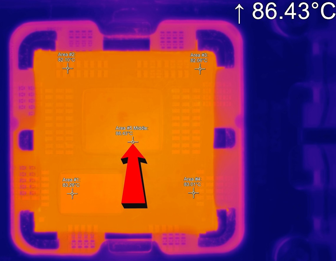
By the way, I also stopped at 87 degrees on the IHS because I would like to continue using the silicon, which was already sizzling away here at about 107 degrees. This would also prove where the delta with the up to 20 Kelvin difference actually comes from:
Substrate -> Oxide -> Solder -> Oxide -> 2.8 mm IHS -> Oxide -> 0.05 mm Phase Changer
What influence this then has on the temperatures, we also see the next and last page.


113 Antworten
Kommentar
Lade neue Kommentare
Veteran
Urgestein
Veteran
Veteran
Urgestein
Mitglied
Urgestein
Veteran
Urgestein
Veteran
Veteran
Urgestein
Mitglied
Mitglied
Veteran
1
Veteran
Urgestein
Urgestein
Alle Kommentare lesen unter igor´sLAB Community →