


Teardown: PCB layout and components
Let’s start with the PCB, whose power supply layout looks a bit tricky again. VDDCR_GFX is the main voltage (GPU) and so this results in a voltage converter design with a total of 6 real phases and the resulting 6 control loops for that alone. In addition, there are two phases for the VDD_SOC and one each for VDDCI_MEM and VDD_MEM. AMD remains true to itself with the partial voltage supply, only the spatial distribution on the board takes some getting used to.
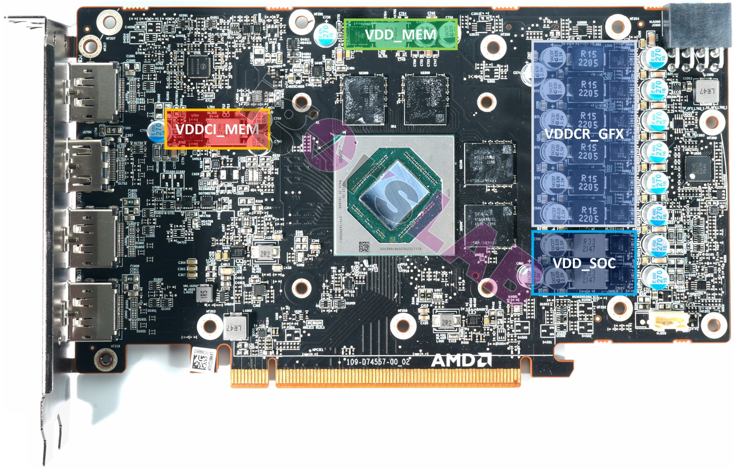
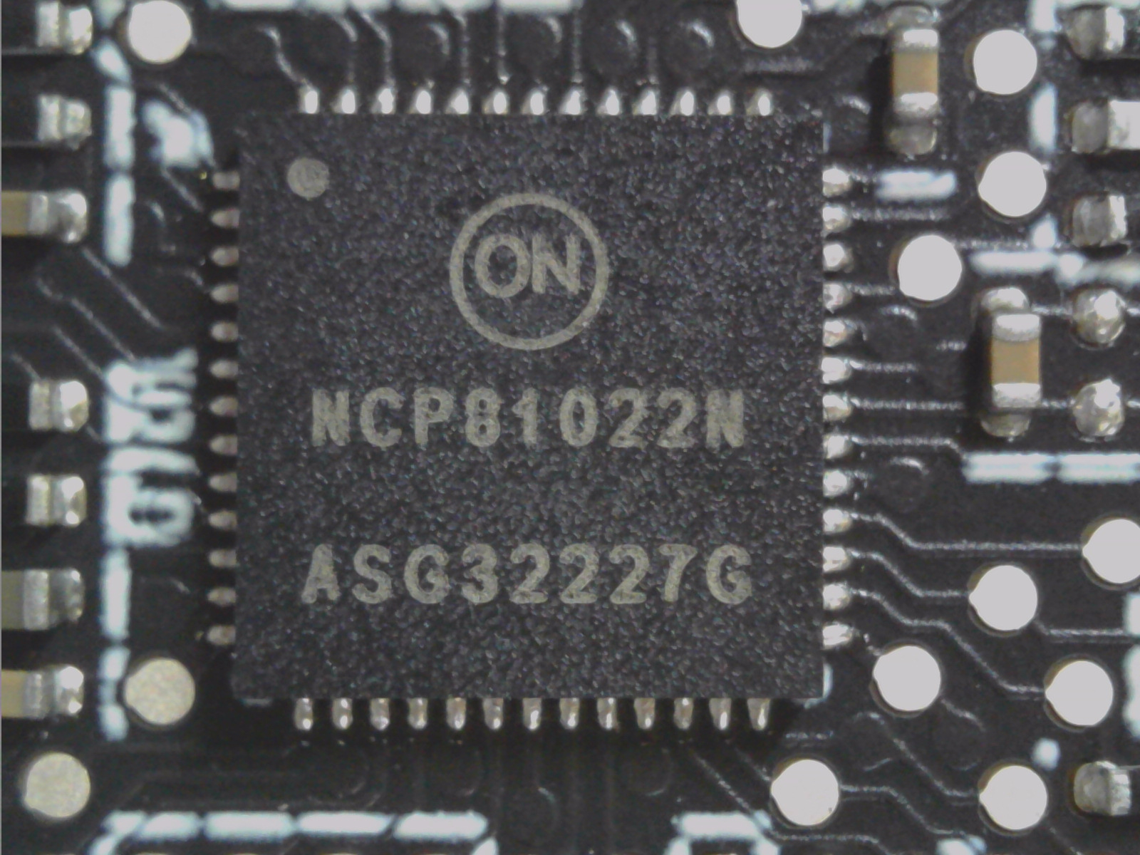
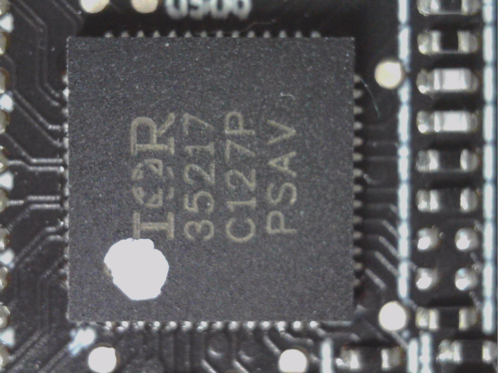
This all looks quite meager at first glance, but it’s enough. The used IR35217 from International Rectifier (we also know this part from many motherboards) is a dual-loop digital multi-phase buck controller and in the layout used here AMD does without doubler chips and works with a total of six real phases for VDDCR_GFX and two phases for VDD_SOC. The generation of VDDCI_MEM is not a big item in terms of performance, but it is important. It is used for the GPU-internal level transition between the GPU and the memory signal, something like the voltage between the memory and the GPU core on the I/O bus. An NCP81022 works here as a second PWM controller, also for VDD_MEM. In addition, one generates other constant sources for various partial voltages. An ultra-low dropout chip generates the very low voltage for the PLL (Phase Locked Loop) section.
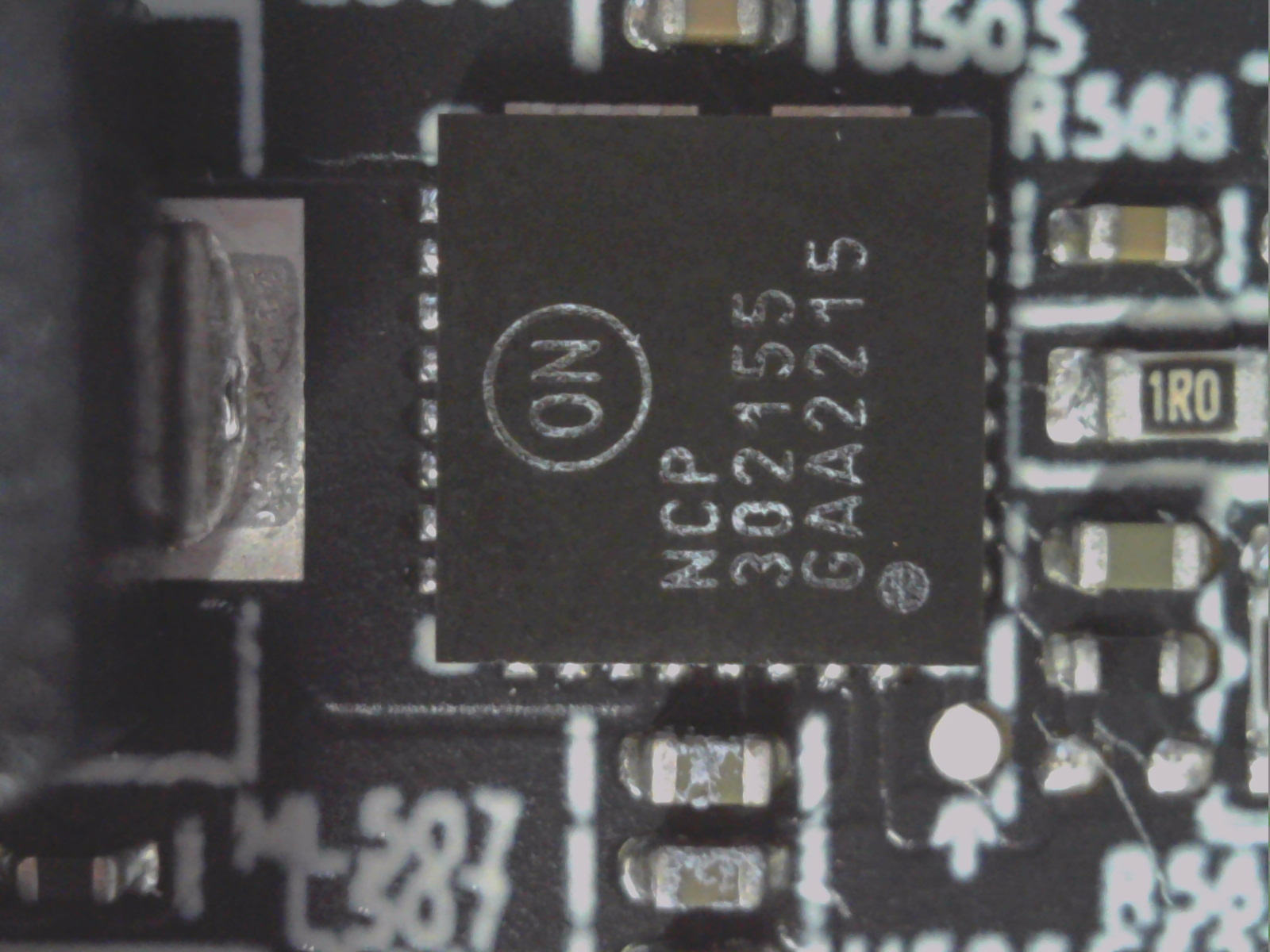
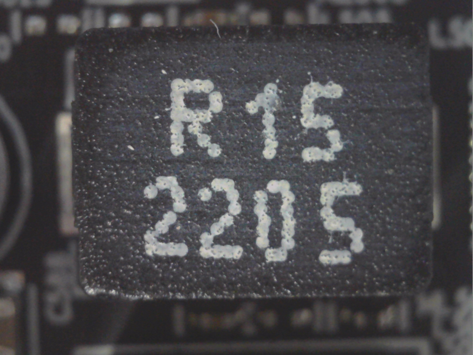
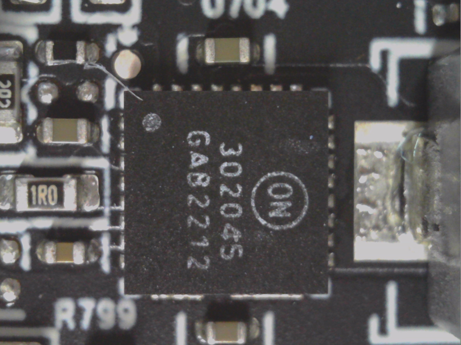
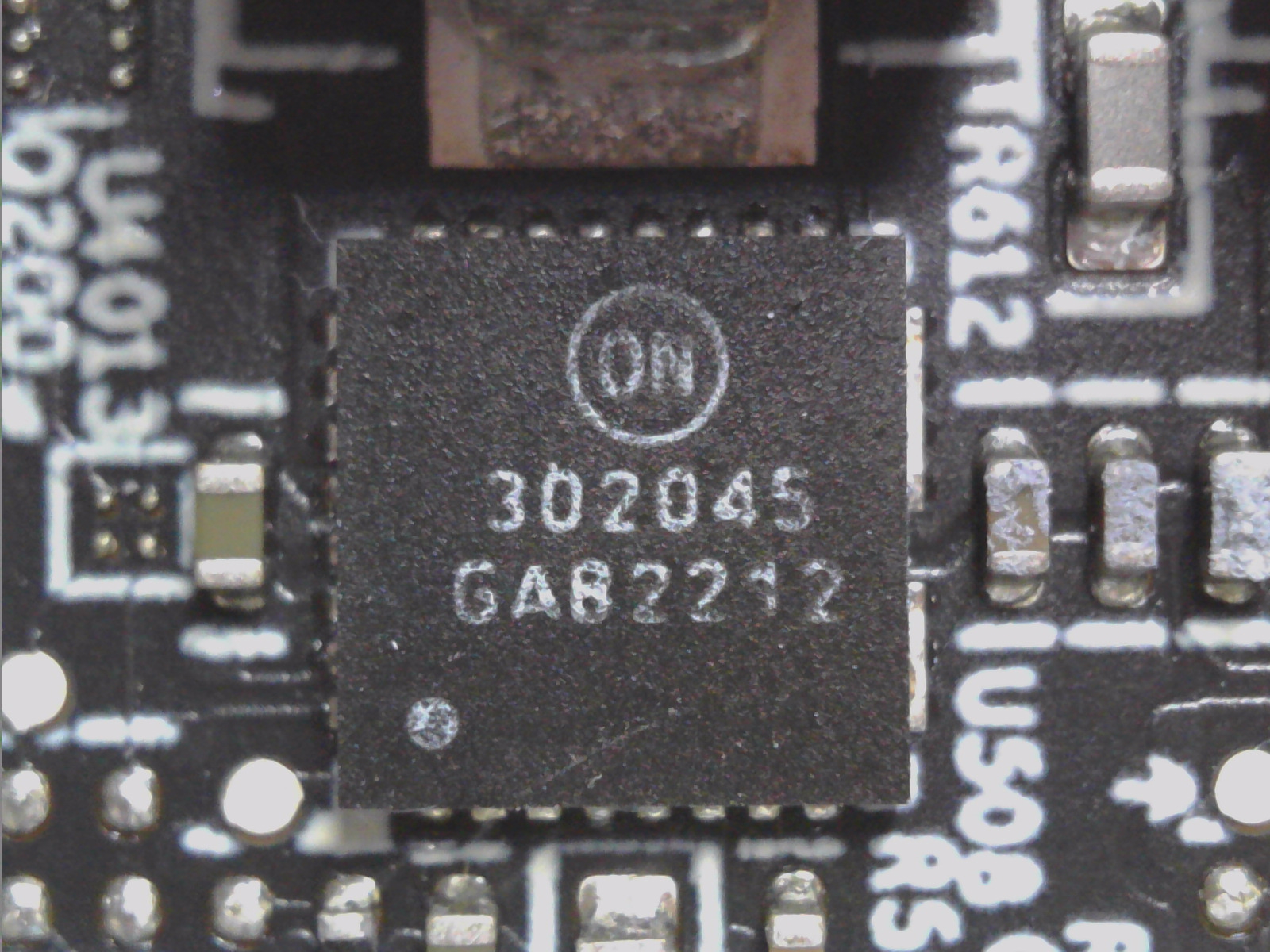
The used DrMOS for VDDCR_GFX are rather cheap products from OnSemi. The NPC302155 with 50A peak current integrates a MOSFET driver, a high-side MOSFET and low-side MOSFET in a single package. The other voltage converters rely on the slightly weaker NCP3020445 with 45A peak current in the same design. This chip is specifically designed for high current applications such as DC-DC buck power conversion applications. This integrated solution reduces board space requirements compared to a discrete component solution. The coils used for VDDCR_GFX have an inductance of 150 nH, while the others have an inductance of 330 nH.


Power supply warning: Does it fit or not?
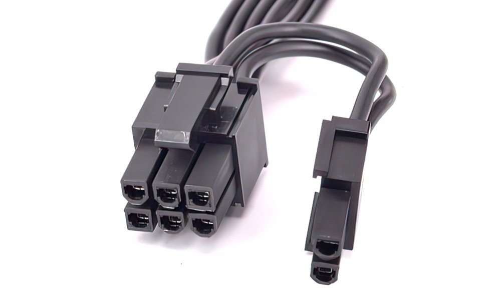
As nice as small gaps may be visually, the 8-pin connector is not a premium trunk lid, but the loading ramp, so to speak. AMD has unfortunately made a faux pas here with the MBA card, because if you want to plug certain 6+2 cables into the 8-pin connector, it leads to a similar problem as with NVIDIA’s funny 12VHPWR connector. The cutout is too small and doesn’t fit every connector.
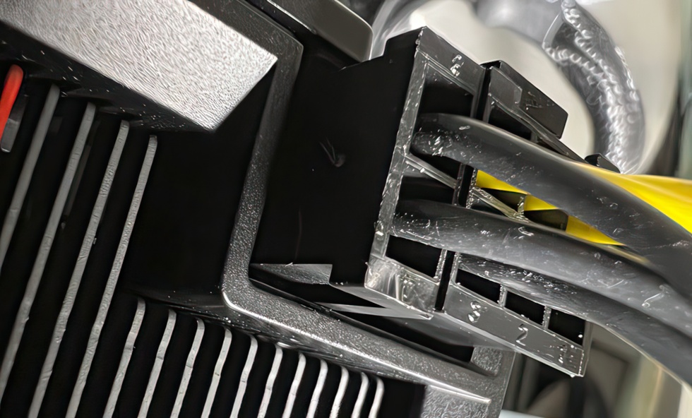
Unfortunately, this leads to the fact that some connectors can’t be inserted all the way, if at all. However, not only NVIDIA’s PCAT or many sleeved modding cables are affected here, but also the native connectors of e.g. Seasonic, if there is an additional guide for the 2-pin connector.
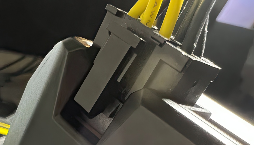
Such connectors unfortunately don’t fit into the socket and real contact problems occur, as nice as that might be with the connection between the two connector halves. It is even dangerous, because in an emergency it is 150 watts and a little more, which are chased through the only half plugged pins and springs, so well over 12 amps. Not as dramatic as with the 12VHPWR, but electrically it’s complete nonsense.

- 1 - Introduction, technical data and technology
- 2 - Test system and igor'sLAB MIFCOM-PC
- 3 - Teardown: PCB, compnents and 8-Pin issues
- 4 - Teardown: Cooler and thermal grease
- 5 - Gaming performance Full-HD (1920 x 1080)
- 6 - Gaming performance WQHD (2560 x 1440)
- 7 - Latencies, DLSS vs. FSR
- 8 - Details: Power consumption and load balancing
- 9 - Transients, capping and PSU recommendation
- 10 - Temperatures, clock rate and thermal imaging
- 11 - Fan curves, noise and sound sample
- 12 - Summary and conclusion


74 Antworten
Kommentar
Lade neue Kommentare
Urgestein
1
Mitglied
Urgestein
Urgestein
Urgestein
1
1
Urgestein
1
Urgestein
Mitglied
Mitglied
Mitglied
Urgestein
Urgestein
Urgestein
Veteran
Urgestein
Alle Kommentare lesen unter igor´sLAB Community →