


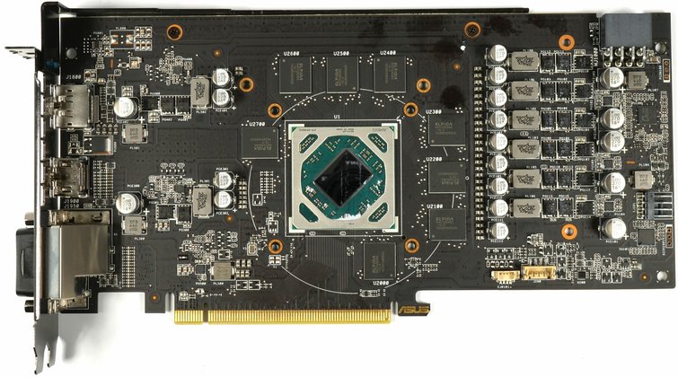
Power supply and layout
The board is a simple multi-layer design by Asus and differs significantly from the old layout of the Asus RX 470 Strix OC. We now take a closer look at the board and see that the power supply of the GPU has moved back to the right, which makes perfect sense if you keep an eye on the paths for the voltage supply and also keep the possible hotspots in mind.
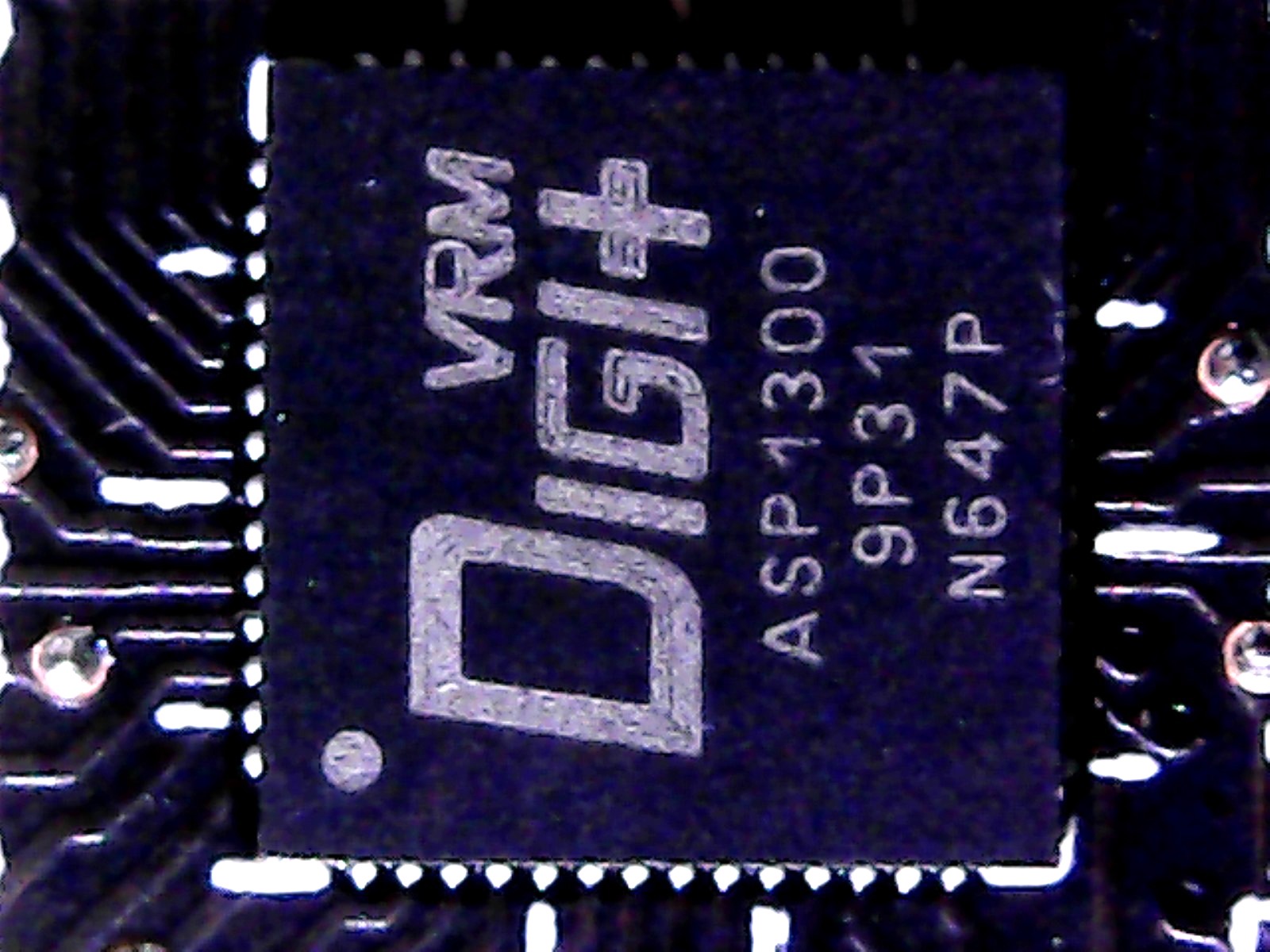
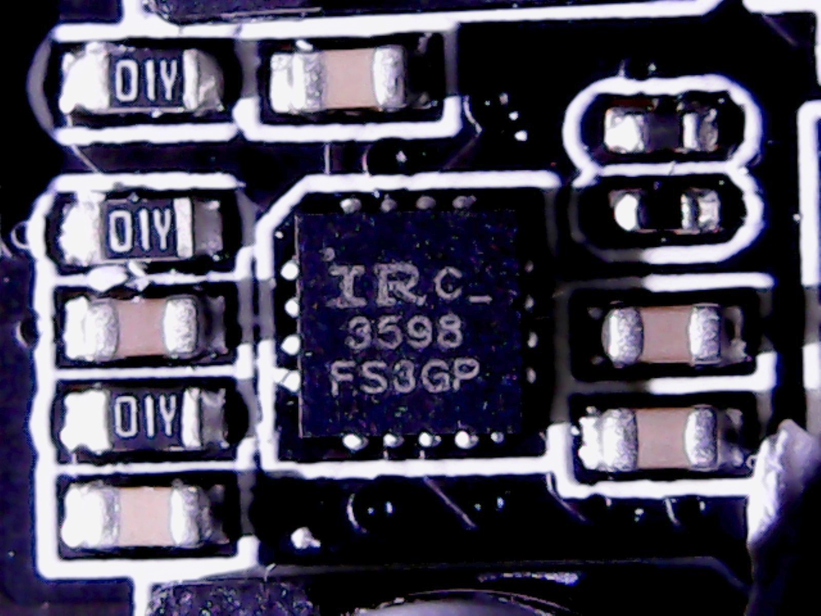
An ASP1300 from International Rectifier / Infineon, which was labeled as ADigi+ for Asus, is used as a PWM controller. But if you take a closer look at the board, you don't need to know the data sheet of the undocumented PWM controller to see that it's actually not six, but only three real phases for GPU power supply. We also find on the board three IR3598 from International Rectifier, which are so-called phase doublers (and gate-drivers).
The trick now is to divide the actual three phases into the six existing voltage regulators, because they are physically present. Thus, a single phase of the controller controls two voltage regulators simultaneously and not just one. The result is, of course, similar, but balancing is much simpler, because the load distribution can now not be carried out on six, but only three regulated phases. Cost down, but acceptable.
 |
 |
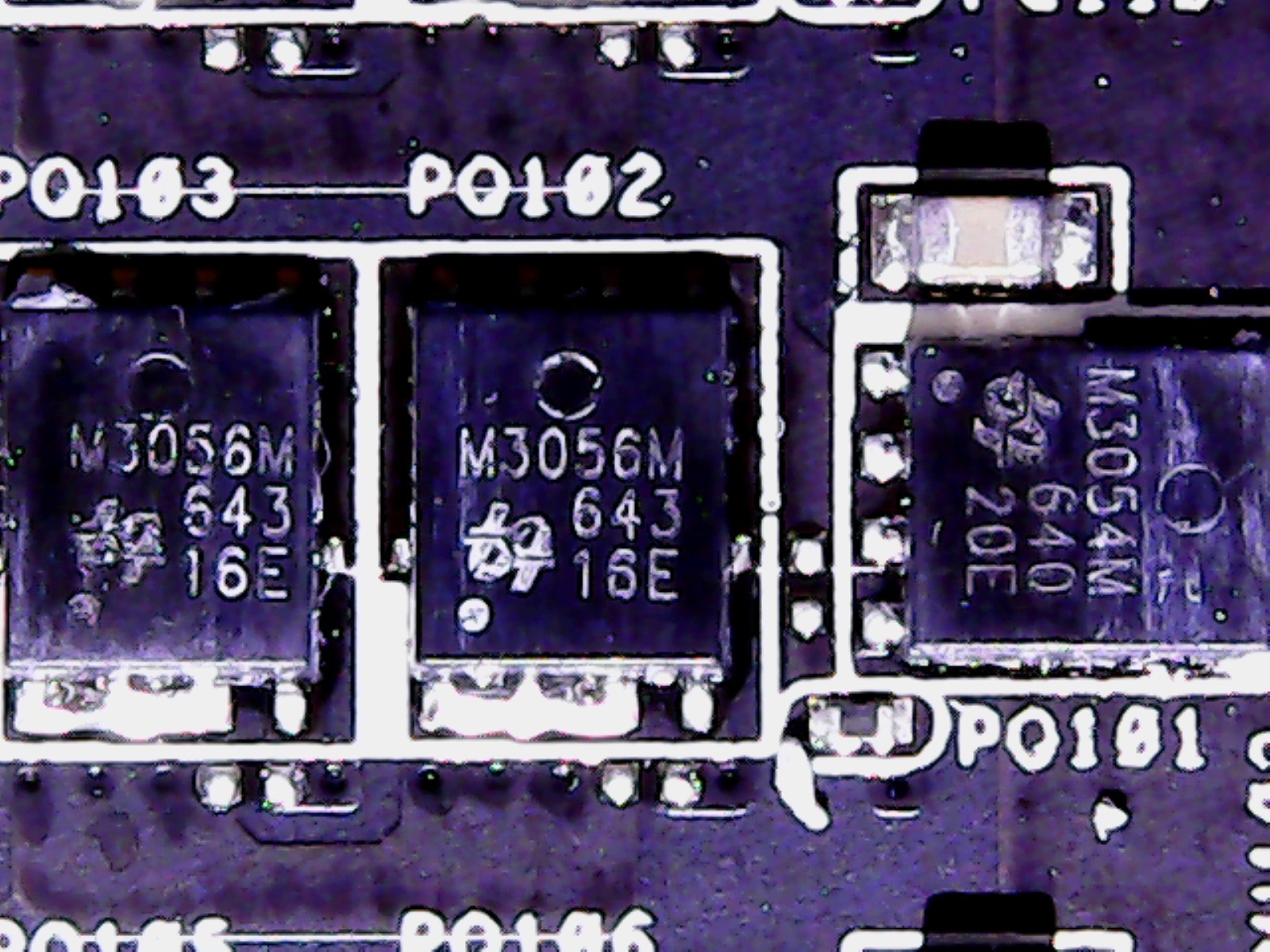
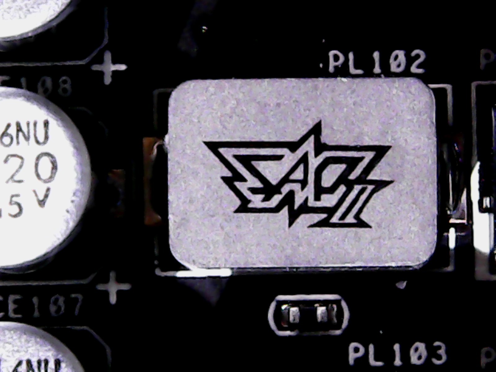
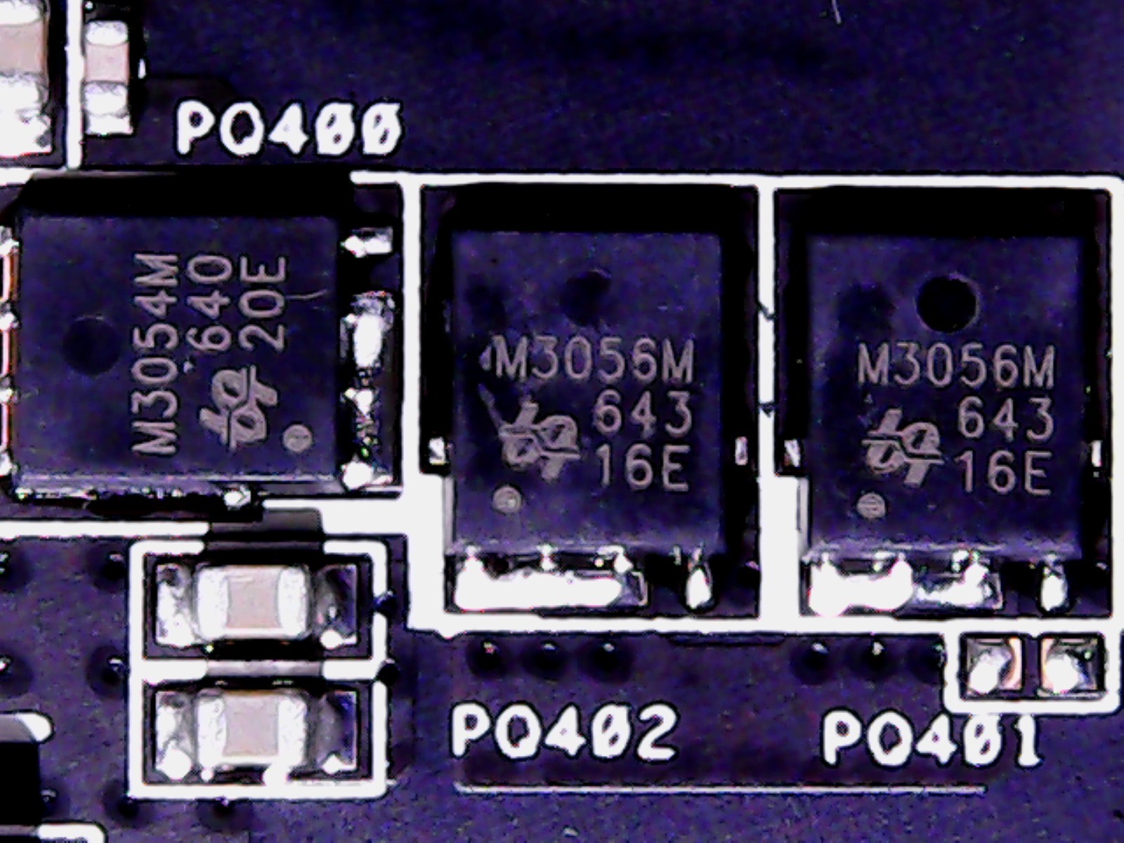
Each of these six voltage regulators is implemented conventionally with one M3054 from UBIQ on the high-side and two M3056 on the low-side. The well-known, encapsulated SAPII ferrite core coils (Super Alloy Power) are used for smoothing, which should have a reduced vibration tendency and less vibration (snoring, fieps) in the intended temperature range.
 |
 |
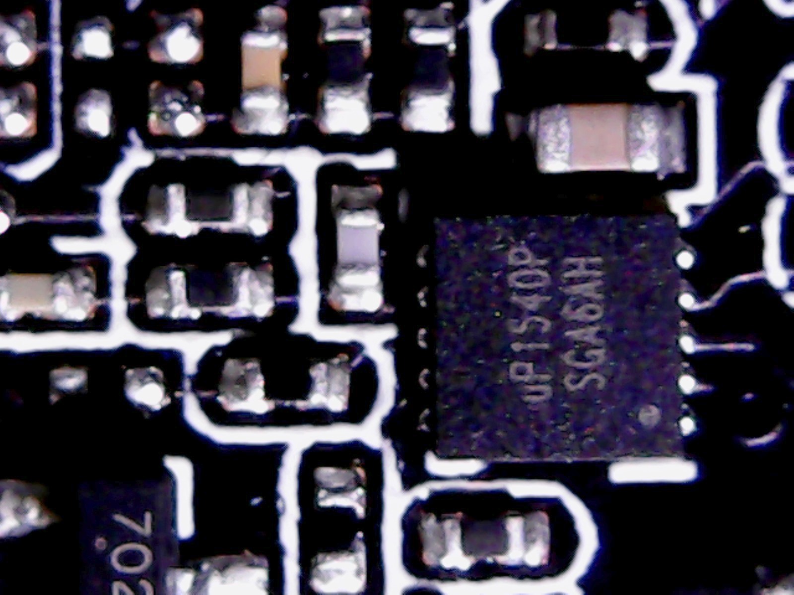
The power supply of the memory is similarly dissolved. The uP1540 from uPI Semiconductor, a Synchronous-Rectified Buck Controller, which is also not officially listed on the manufacturer's website and is manufactured exclusively as an OEM product, controls the voltage converters in question, which are installed on the high and high Low-side identical to those of the GPU power supply are equipped with the same MOSFETs. The power is supplied exclusively via the motherboard slot. The chip also includes a Boostrap diode and gate driver for the MOSFETs.
 |
 |
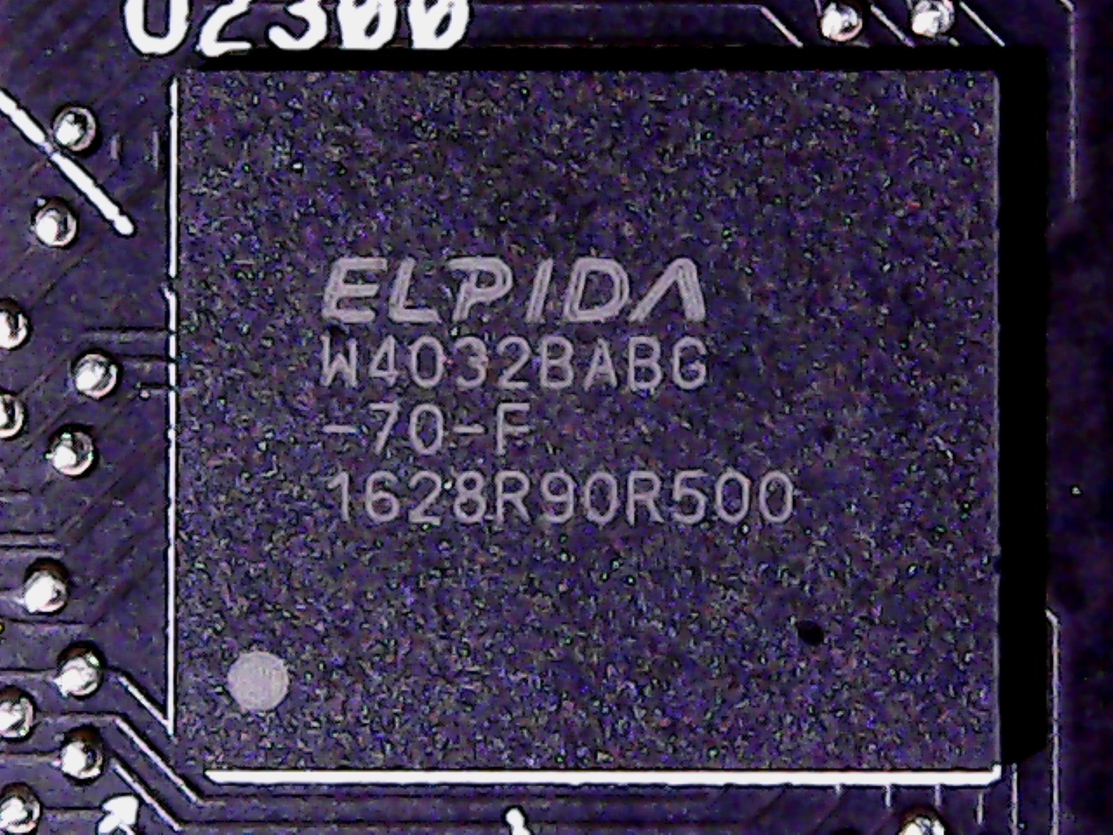
The memory comes on this map of Elpida. The built-in W4032BABG-70-F is eight 4-GBit modules (16x 256 MBit), which reach a maximum of 1750 MHz and have already been found on some other board partner cards, such as the GeForce GTX 970 of some manufacturers. However, there is not much overclocking margin with this memory, especially since the memory is not actively cooled and Elpida modules are not positive in the past due to robustness when exceeding the temperatures indicated in the specs. have been noticed.
 |
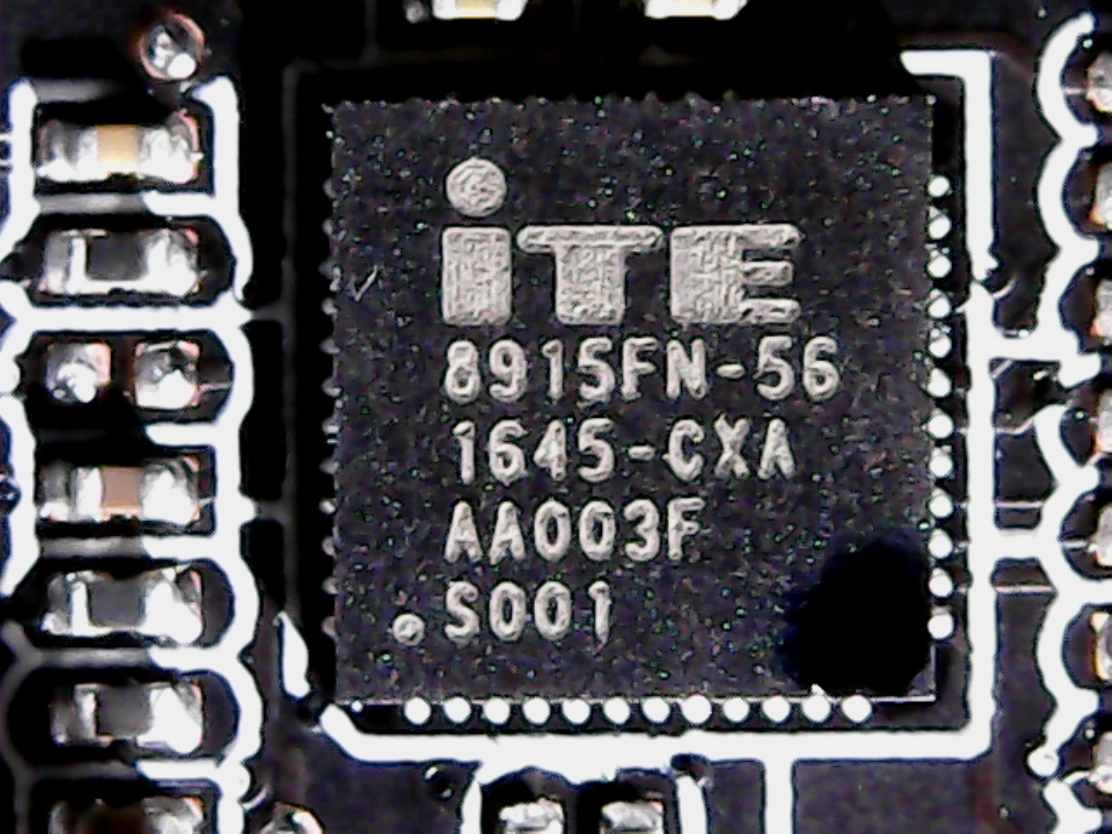 |
From obviously quite likes to rely on undocumented, own OEM versions, because the ITE8915 is also rather sparsely blessed with information as a controller and monitoring chip. Overall, the placement is standard in class, but we suspect current peaks based on the layout and the somewhat too granular balancing on the motherboard slot, which could well reach the limits of the standards recommended by the PCI SIG. But we will see what can be measured in real terms later.
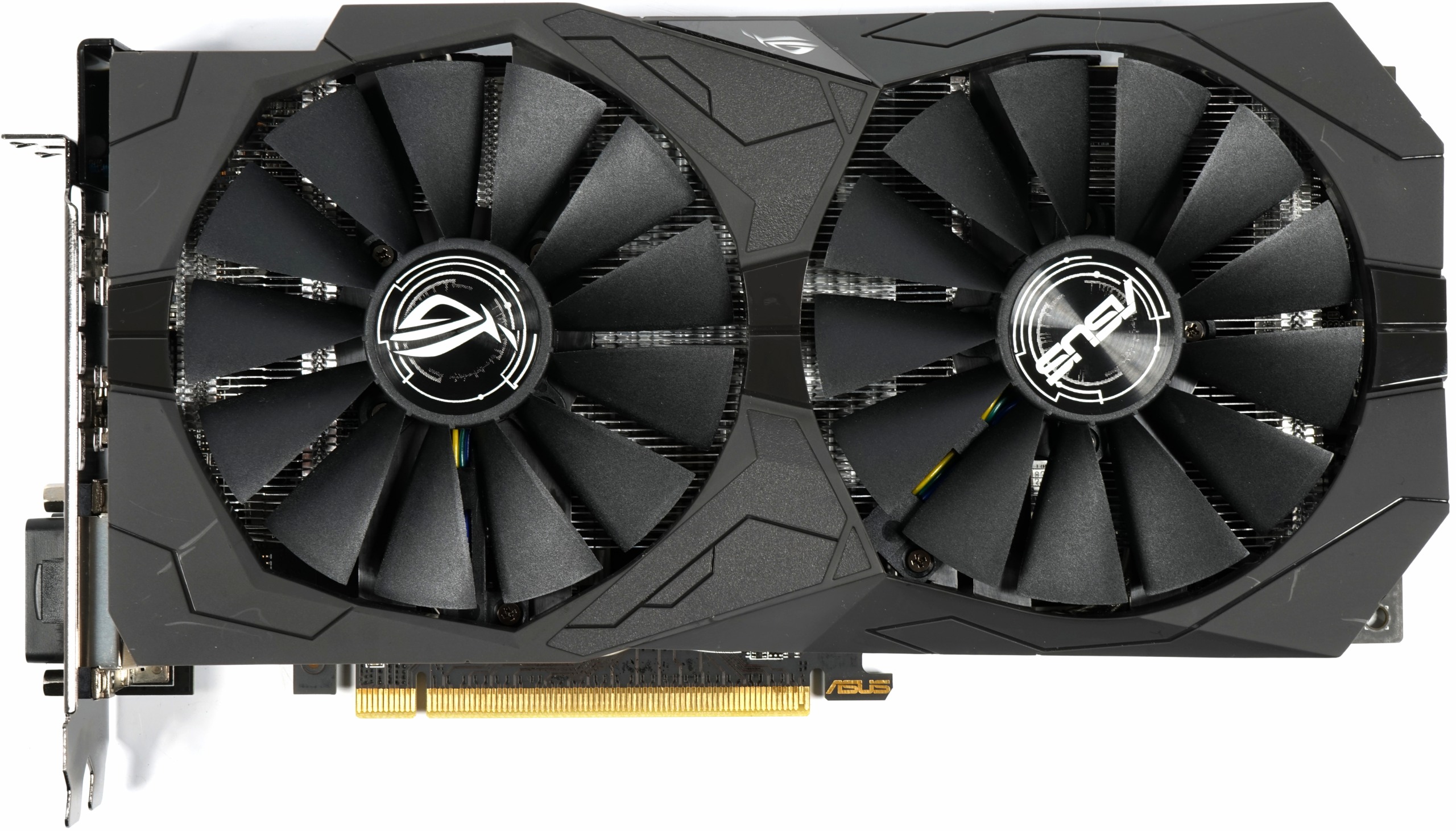
The cooling concept in detail
The cooler looks downright small and slim, which is not changed by the quite large rotor blades of the fans. With a maximum of 2500 rpm, these fan modules, whose rotors have a diameter of 95 mm and have a total of 13 rotor blades, are located in the lower midfield. They are designed for static, direct pressure and must also reach components and rib coolers below the actual heat sink.
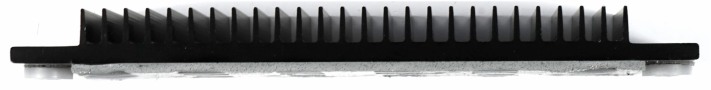
This applies in particular to the VRM cooler, in which Asus relies on a small piece of blackened strand aluminium, which sits on the MOSFETs with an in-between thermal guide pad and is fixed on the back by screws.
On the other hand, you can't find an actively helping backplate and the storage on the top does not have any cooling aid, but has to cope with the air flow alone.

With its nearly 340 grams for the metal construction, the cooler is a real lightweight and has two 6 mm heat pipes made of nickel-plated composite material, which have been pressed and sanded into the aluminium heat sink. This is to allow them to have direct contact with the GPU (Direct Heat Touch), where by the main purpose of optimizing costs. The rest is marketing.
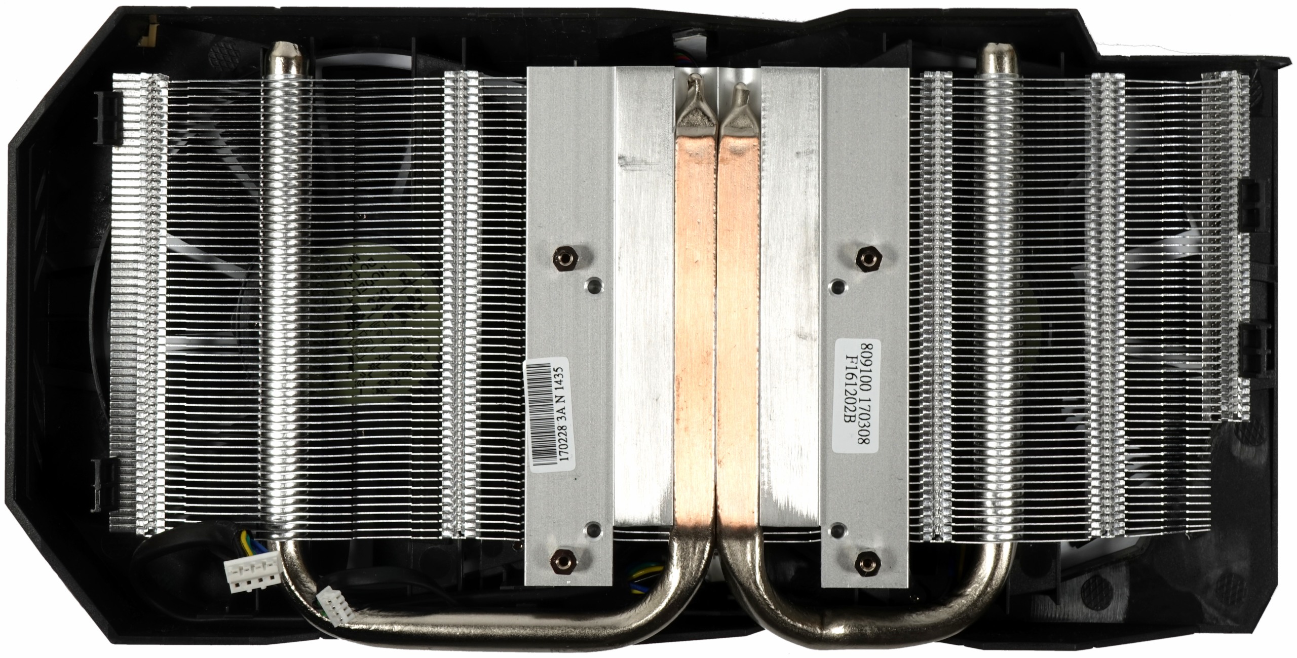
Whether and how this flyweight copes with the occurring power dissipation, the test must later show in the open structure and in the closed housing


Kommentieren