


Board analysis
The board of the MSI GTX 1650 Gaming X is not only very tidy, there is almost a yawning emptiness. The manufacturer relies on a 3+1 phase design, which proves to be completely sufficient in view of the maximum power limit of this card. With a good 33 watts per GPU phase as the maximum load, this placement is quite useful and even for the 4 GB of memory a stable supply phase is actually quite sufficient.
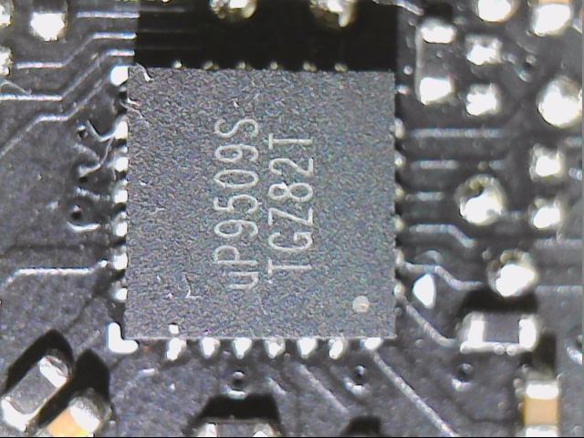
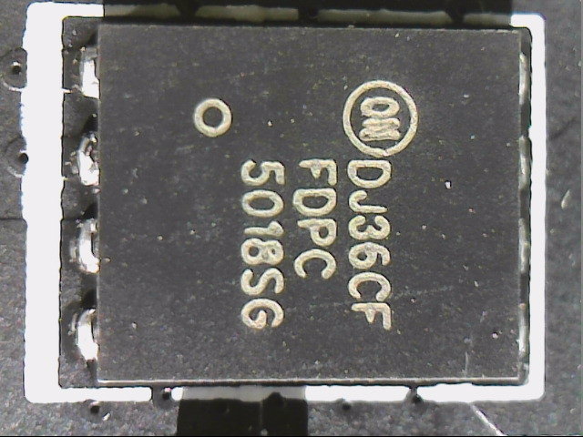
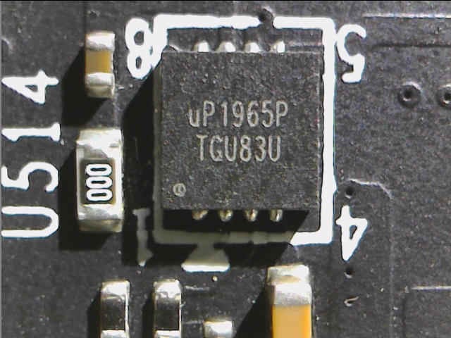
On the left we see the three GPU phases with the three MSI-labelled coils and the three FDPC 5013SG from ON Semiconductor, which are asymmetric dual-N-channel MOSFETs. The necessary gate drivers are already integrated in the uP9509S, which is located directly behind the back and acts as a PWM controller. This fairly new 3 phase PWM controller from UPI Semiconductor is a cost-effective solution that is recommended for designs with one, two or three phases and dual MOSFETS in direct control. The PWM controller in the form of the uP1965P from UPI Semiconductor for one storage phase is located to the left of the 2-pin LED connector above the three CPU phases.
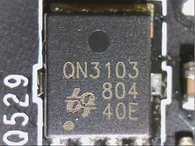
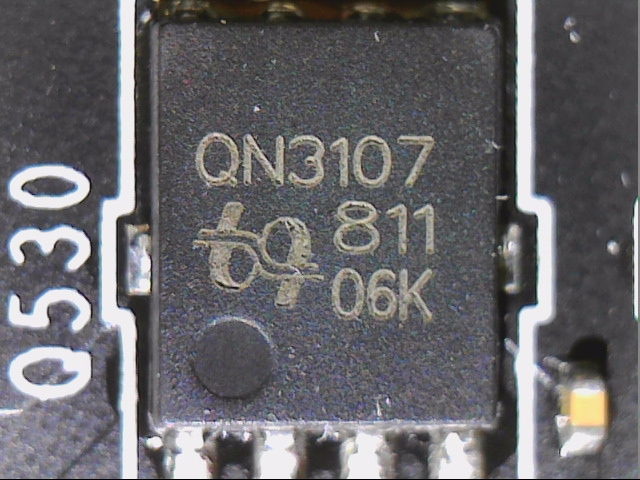
However, the MOSFETS of the voltage converter and the coil sit to the right of the GPU and the memory rather centered below another, simpler buck controller. While the high-side in the input is equipped with a QN3103G from UBIQ, two 2x QN3107G from UBIQ provide the necessary currents on the low-side. Both types are simple N-channel MOSFETs. MSI uses cheap cup capacitors instead of the SMD caps, because you have space without end.
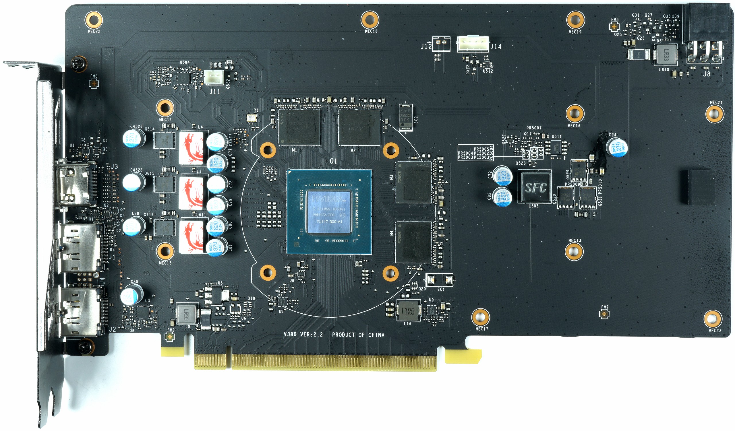
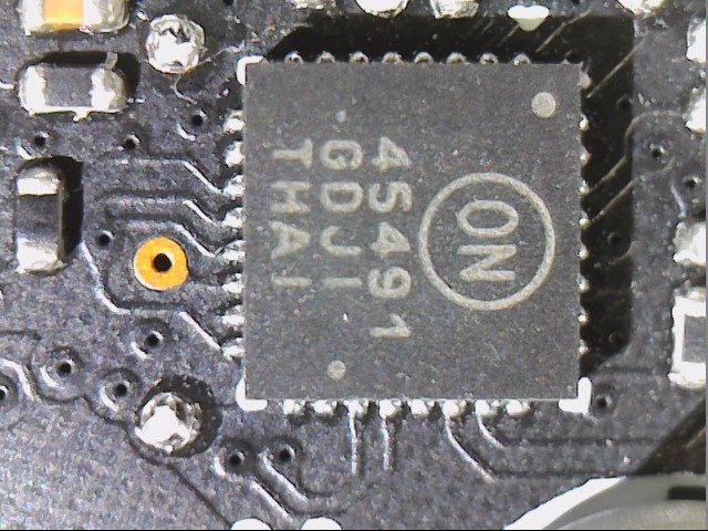
The input smoothing of the supply connections is carried out via a simple 330 mH longitudinal coil, followed by a shunt for real-time determination of the voltages and flowing currents as well as the resulting power target(S)-monitoring of these two 12-volt rails is carried out by an NCP45491-D from ON Semiconductor, which represents a shunt controller (voltage/current monitor). Also interesting is the entrance part of the 3.3-volt rail, which again plays a role in this card. But more on that later.
The following table contains the most important components:
GPU Power Supply |
||
|---|---|---|
| PWM Controller | uP9509 UPI Semiconductor 1/2/3-phase PWM controller |
 |
| Gate Driver | Integrated | |
| Vrm | 3x FDPC 5013SG ON Semiconductor Asymmetric Dual-N-Channel MOSFET |
 |
| Coils | 3x Ferrite Choke (Encapsulated Ferrite Core Coils) |  |
Memory and power supply |
||
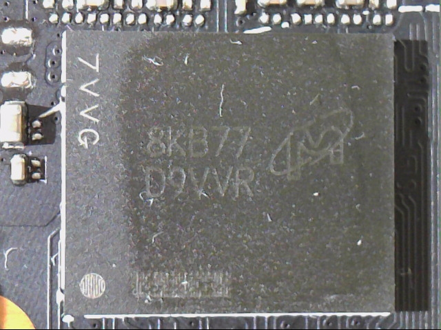
| Modules | 4x MT51J256M32HF-80:B Micron 1 GB GDDR5 SGRAM modules |
 |
| PWM Controller | uP1965P UPI Semiconductor 1-Phase PWM Controller |
 |
| Vrm | High Side: 1x QN3103G UBIQ N-Channel MOSFETLow Side: 2x QN3107G UBIQ N-Channel MOSFET |
|
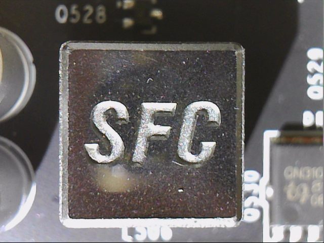
| Super Ferrite Choke (Encapsulated ferrite core coil) |
 |
|
Other components |
||
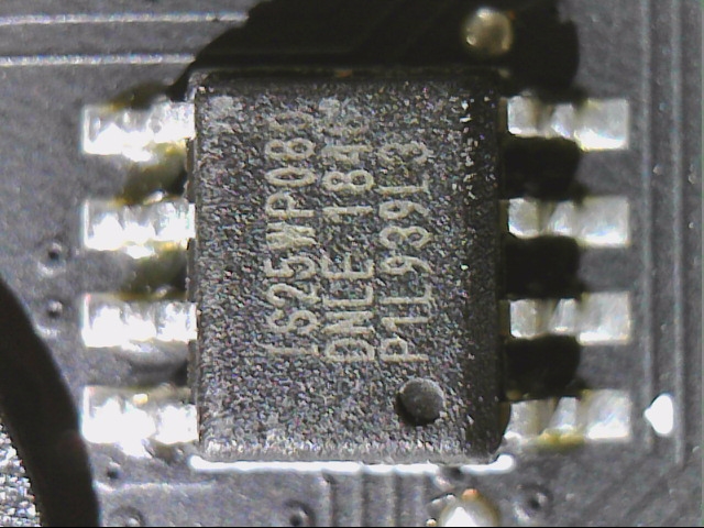
| Eeprom | 25WP080 EEPROM, Single BIOS |
 |
| Shunts | Coil (smoothing), shunt and fuse per 12V rail (2x) | 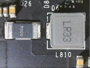 |
| Shunt Controller | NCP45491-D ON Semiconductor Shunt Controller (Voltage/Current Monitor) |
 |
More details |
||
| Other Features |
– 1x 6-pin PCI-Express connection for power supply – Filter coil and fuse in the input area |
|
The cooler in detail
The overall design of the entire cooling construction is as simple as it is effective. For the small chip, a single, overflowing and ground 8 mm heatpipe is sufficient. It is located directly on the GPU as a DHT design and is also pressed into the aluminium heatsink, which cools the superrising GPU surfaces and two memory modules via two 1.5 mm thick thermal pads. The other two modules have direct contact with the heat sink fins bent as further heatsink via a thermal conductive pad of the same thickness.
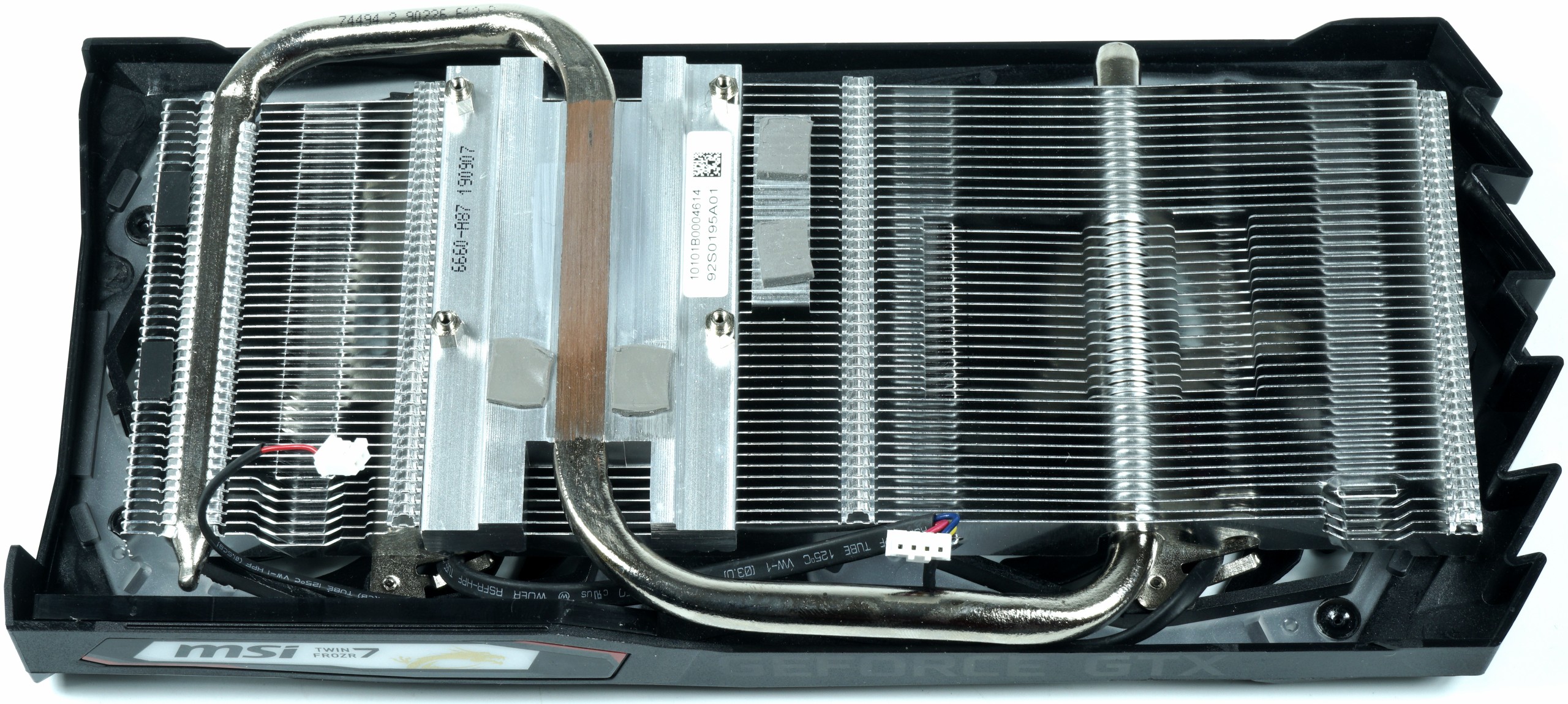
Cooling of the voltage conversion is carried out exclusively via the air flow. The two 8.5 cm fans, each with 14 rotor blades, share a common connection cable, with the fan serving as the master over the GPU. a separate control is not provided. You can't find a backplate, it's obviously fallen victim to pricing.
| Cooling system at a glance | |
|---|---|
| Type of cooler: | Air |
| Heatsink: | Aluminum, DHT with a heatpipe |
| Cooling fins: | Aluminum, horizontal alignment related |
| Heatpipes | 1x 8 mm, nickel-plated copper composite |
| VRM cooling: | No |
| RAM cooling | About Heatsink |
| Fan: | 2x 8.5 cm fan, 14 rotor blades semi-passive lyrised |
| Backplate | No |
- 1 - Einführung, Unboxing, Chip-Details und Testsystem
- 2 - Tear Down: Platinen- und Kühleranalyse
- 3 - Ashes of the Singularity
- 4 - Battlefield V
- 5 - Destiny 2
- 6 - The Division 2
- 7 - Far Cry 5
- 8 - Forza Horizon 4
- 9 - Ghost Recon
- 10 - Grand Theft Auto V
- 11 - Metro Last Light
- 12 - Shadow of the Tomb Raider
- 13 - The Witcher 3
- 14 - Wolfenstein II
- 15 - Leistungsaufnahme und Netzteilempfehlung
- 16 - OC, Taktraten, Temperatur, Infrarot
- 17 - Lüfter und Lautstärke
- 18 - Zusammenfassung und Fazit


Kommentieren