


Assembly
It seems to be becoming more and more standard for the manufacturer to provide a video in addition to written instructions on paper or as a PDF. In my opinion, this is a very welcome development, which is why I don’t want to withhold the clip:
But don’t worry, I’ll go through everything step by step here too. The first hurdle is to find enough space for the assembly. I had to do it on my office desk because of the pictures, but I would recommend a dining or living room table. Something at a comfortable height, at best with easy access from all sides.
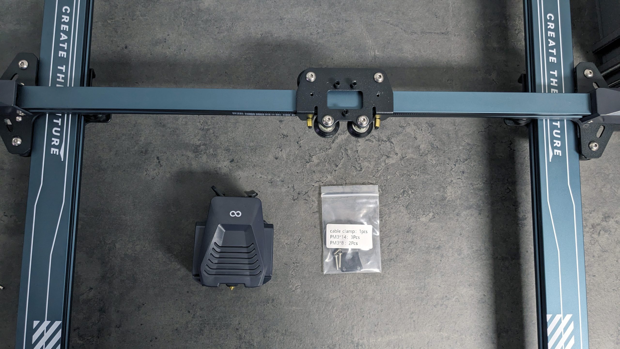
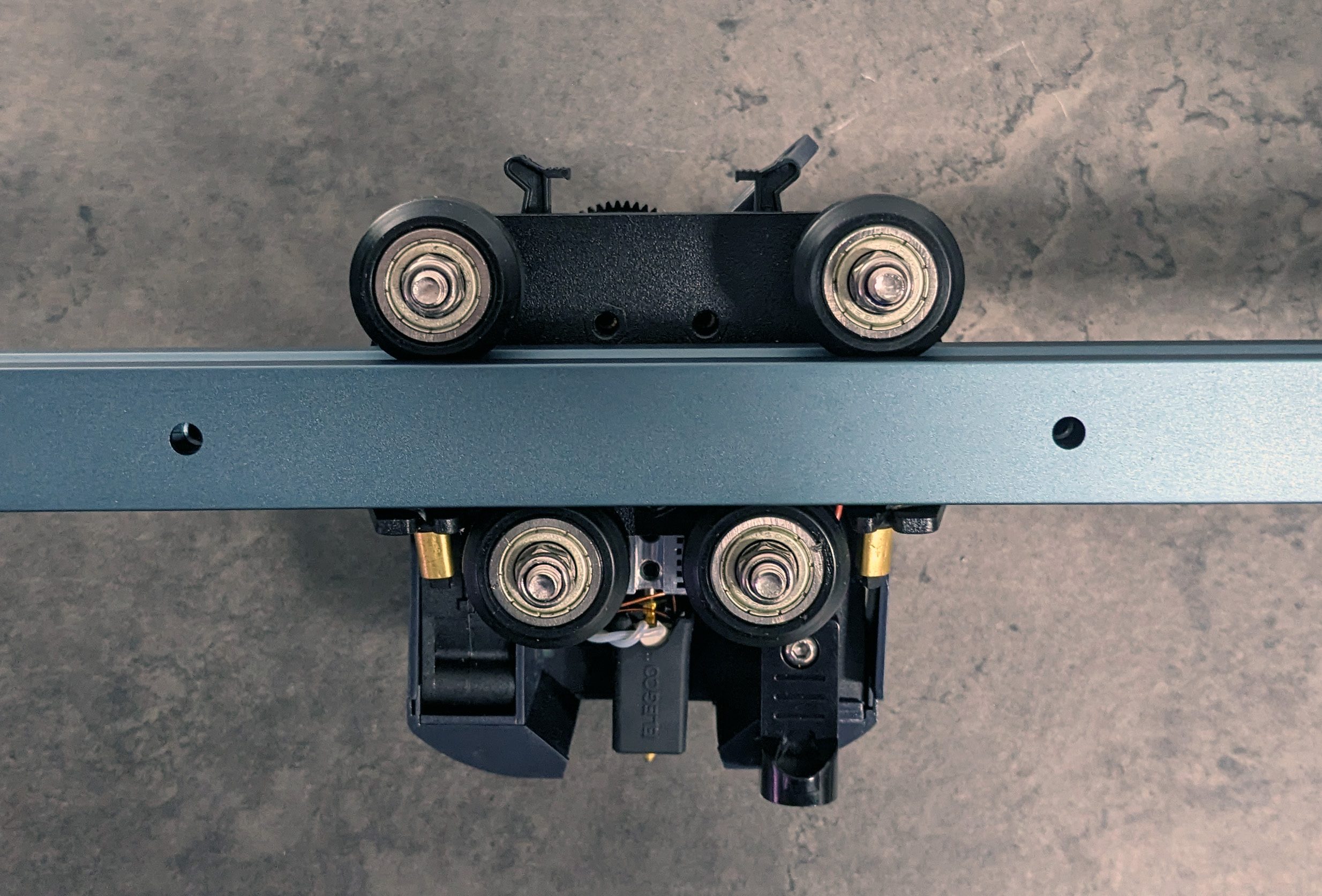
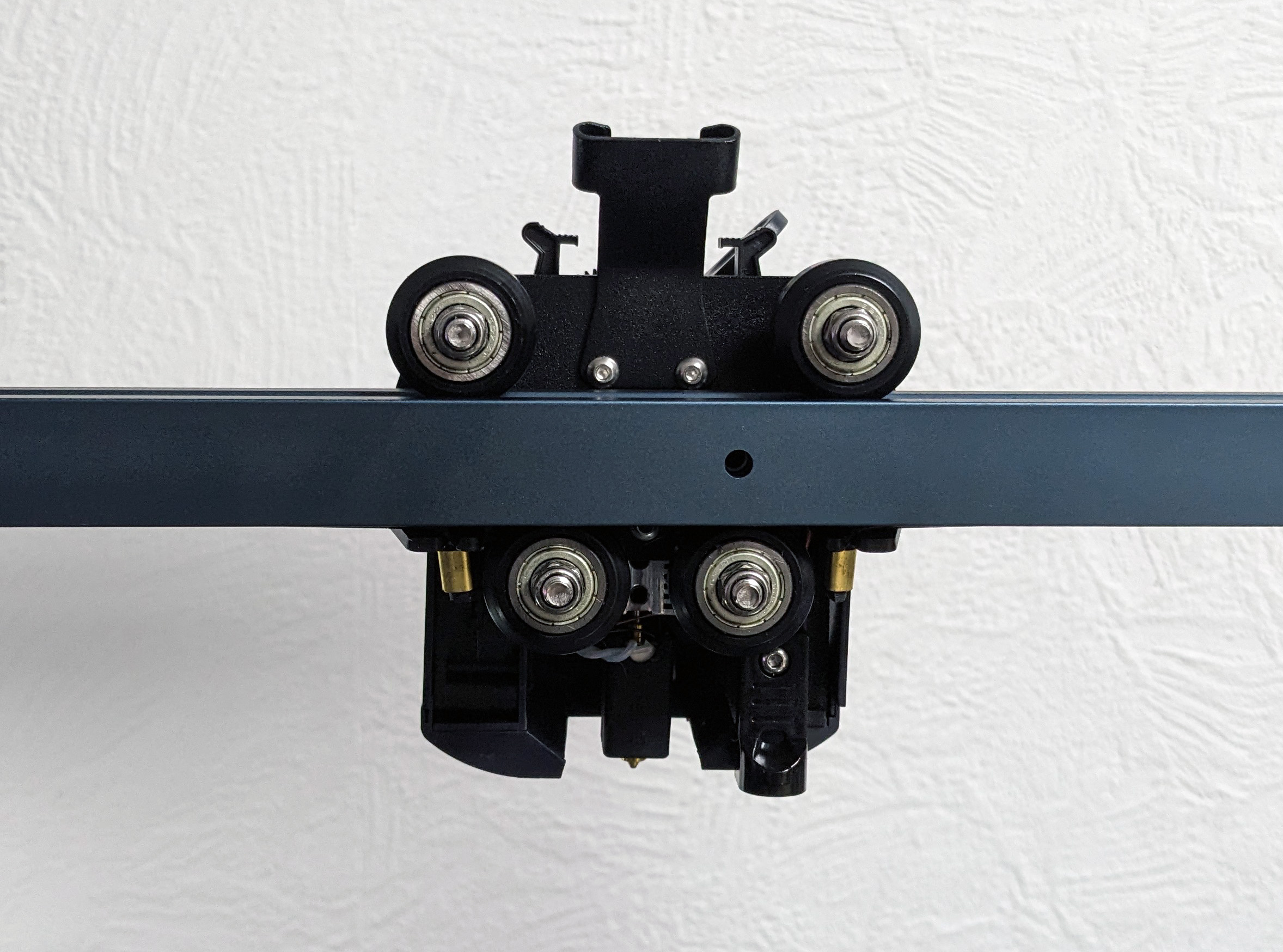
You can start by attaching the extruder to the gantry frame or portal.
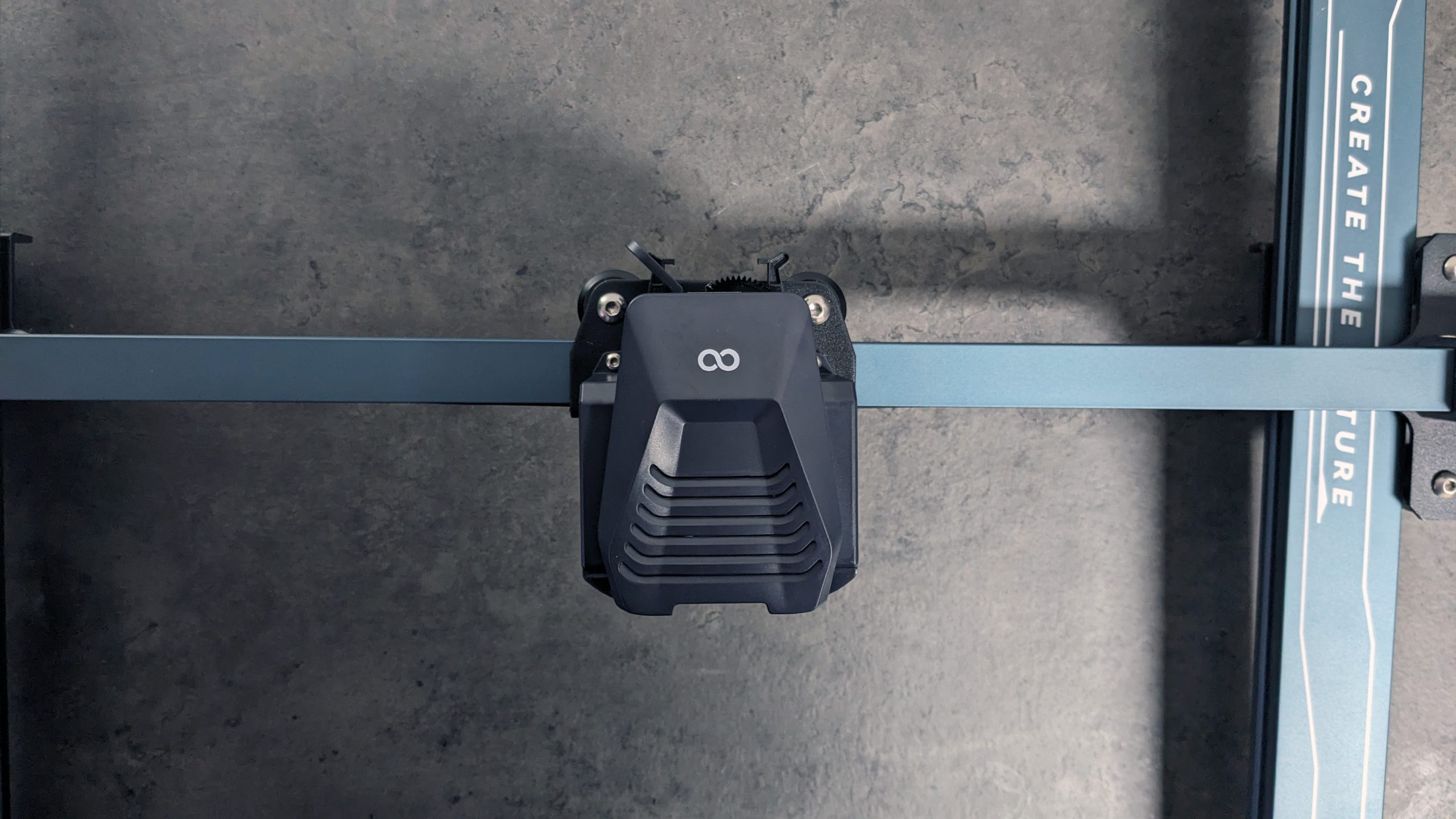
Once the screws to the left and right of the print head have been properly tightened, it is best to turn the whole thing over completely.
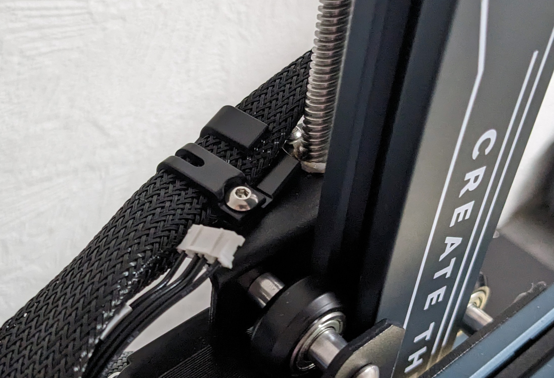
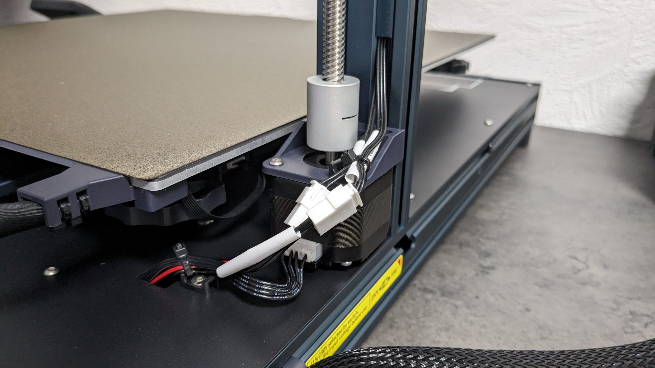
The holder for the cable must then be fixed in place and a third screw inserted into a slightly hidden thread below the X-axis.
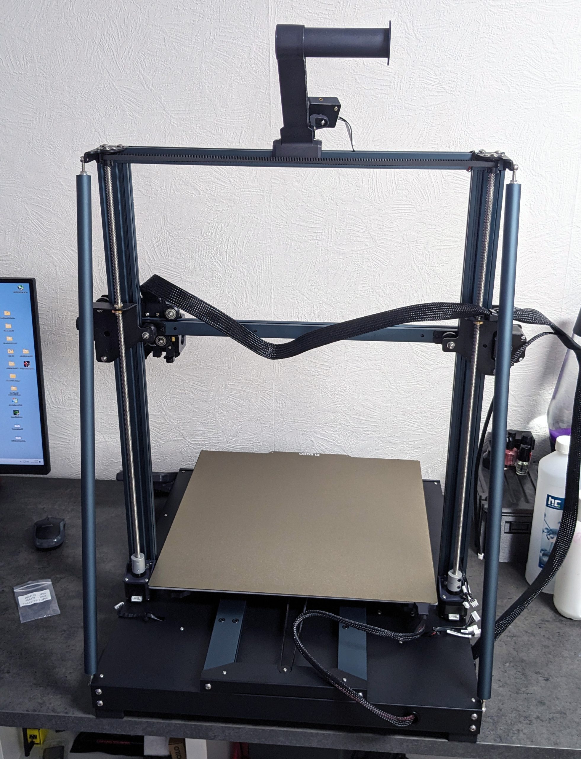
At this point at the latest, a little more space is required, as the portal must be connected to the base.
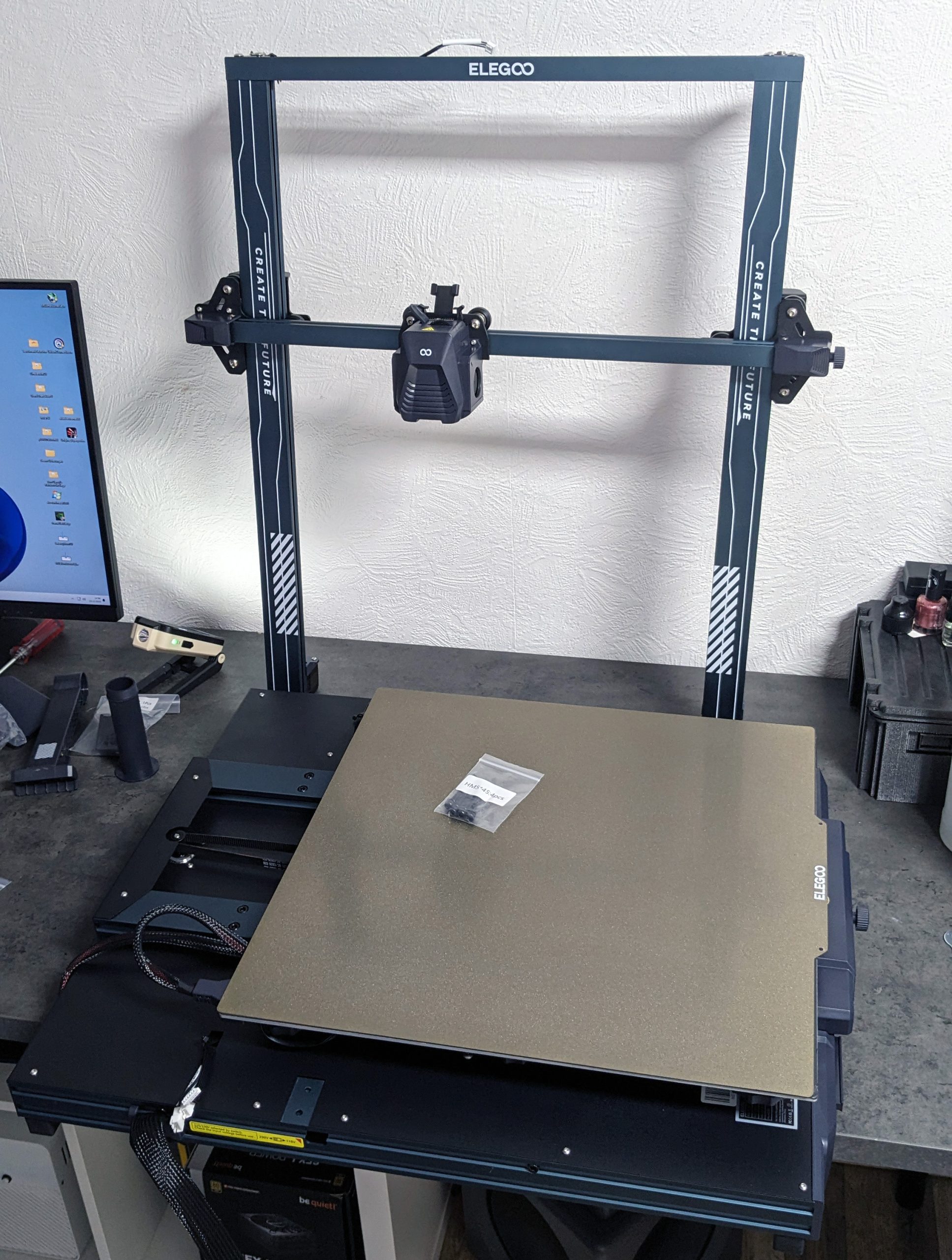
Again, my tip is to let the base protrude slightly over the edge of the table and then tighten the screws alternately on both sides of the printer.
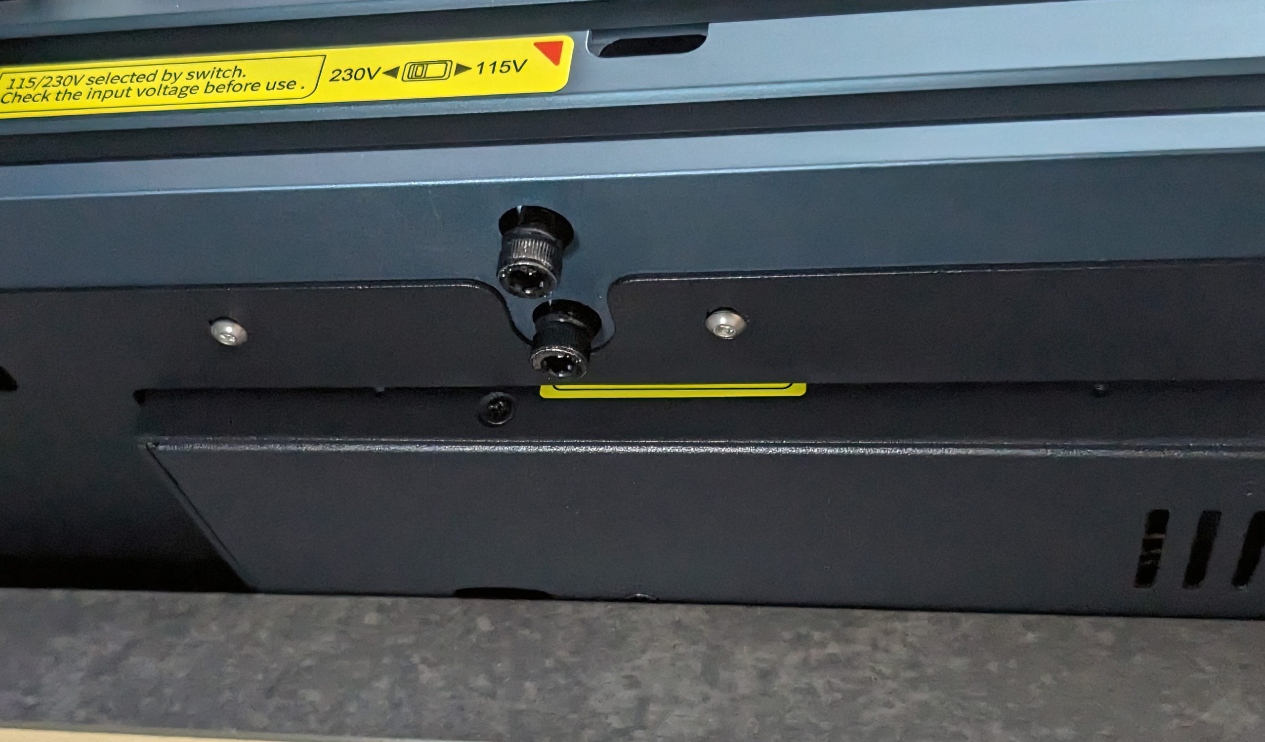
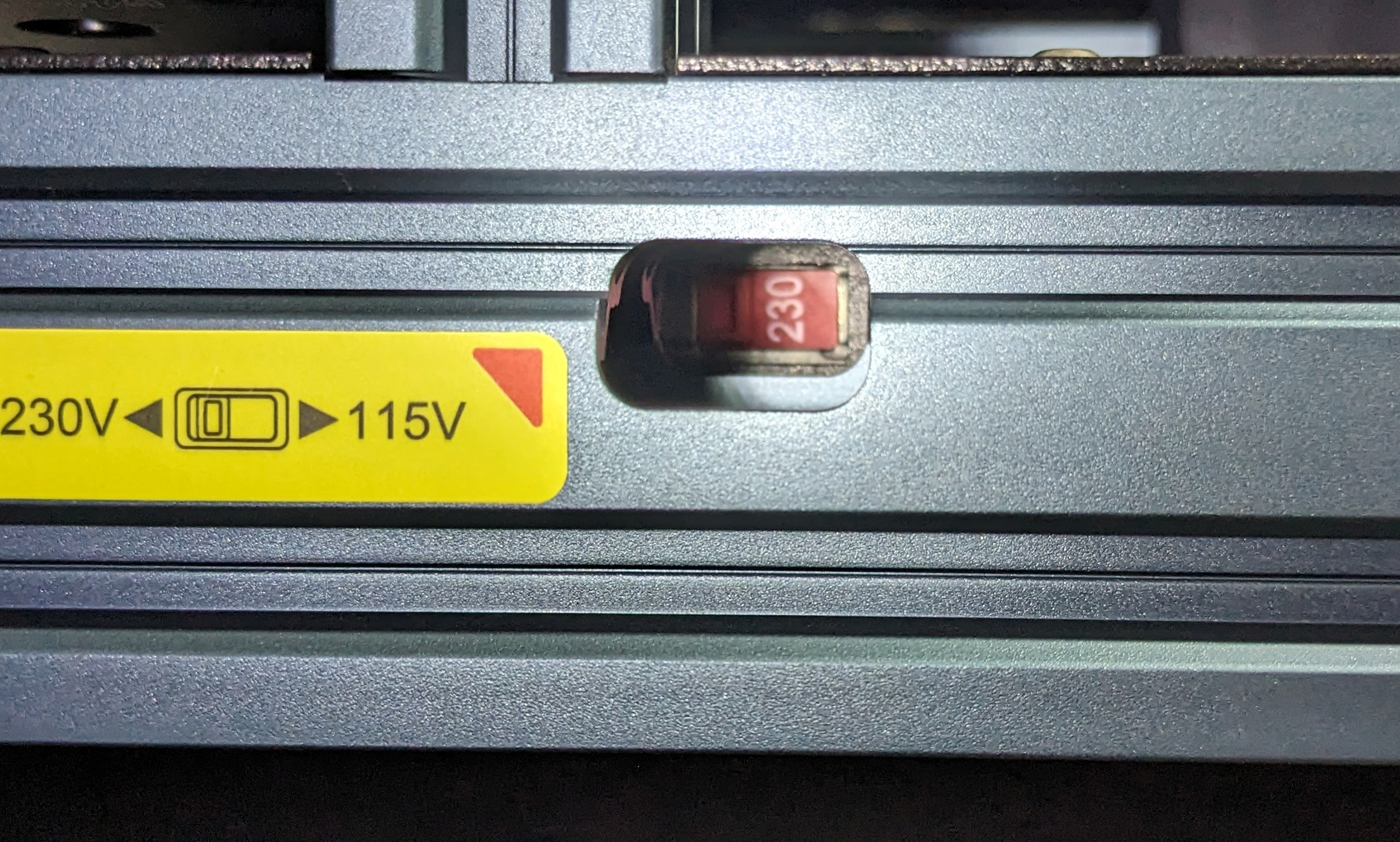
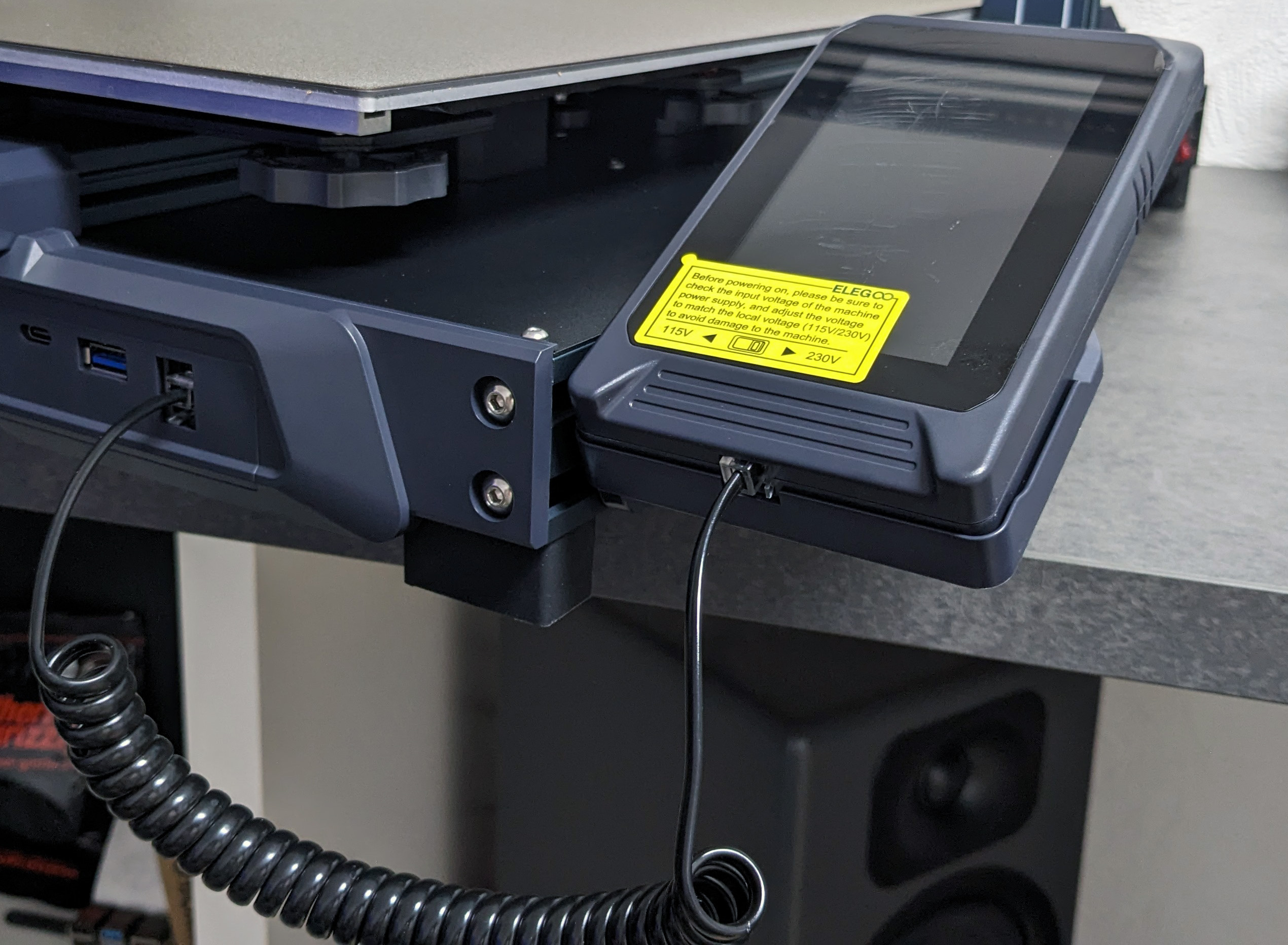
And if you are “in the vicinity” anyway, please set the correct voltage on the power supply unit.
During transportation, the large print bed is held in place by several plastic parts, which must now be removed.

It is then a good idea to mount the holder for the touch display.
And the magnetic module immediately afterwards, the cable can also be connected.
There should already be two movable T-nuts in the extrusion at the top of the printer.
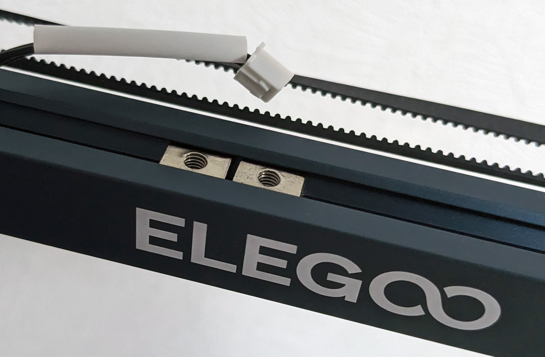
The filament holder is installed in these in the next step.
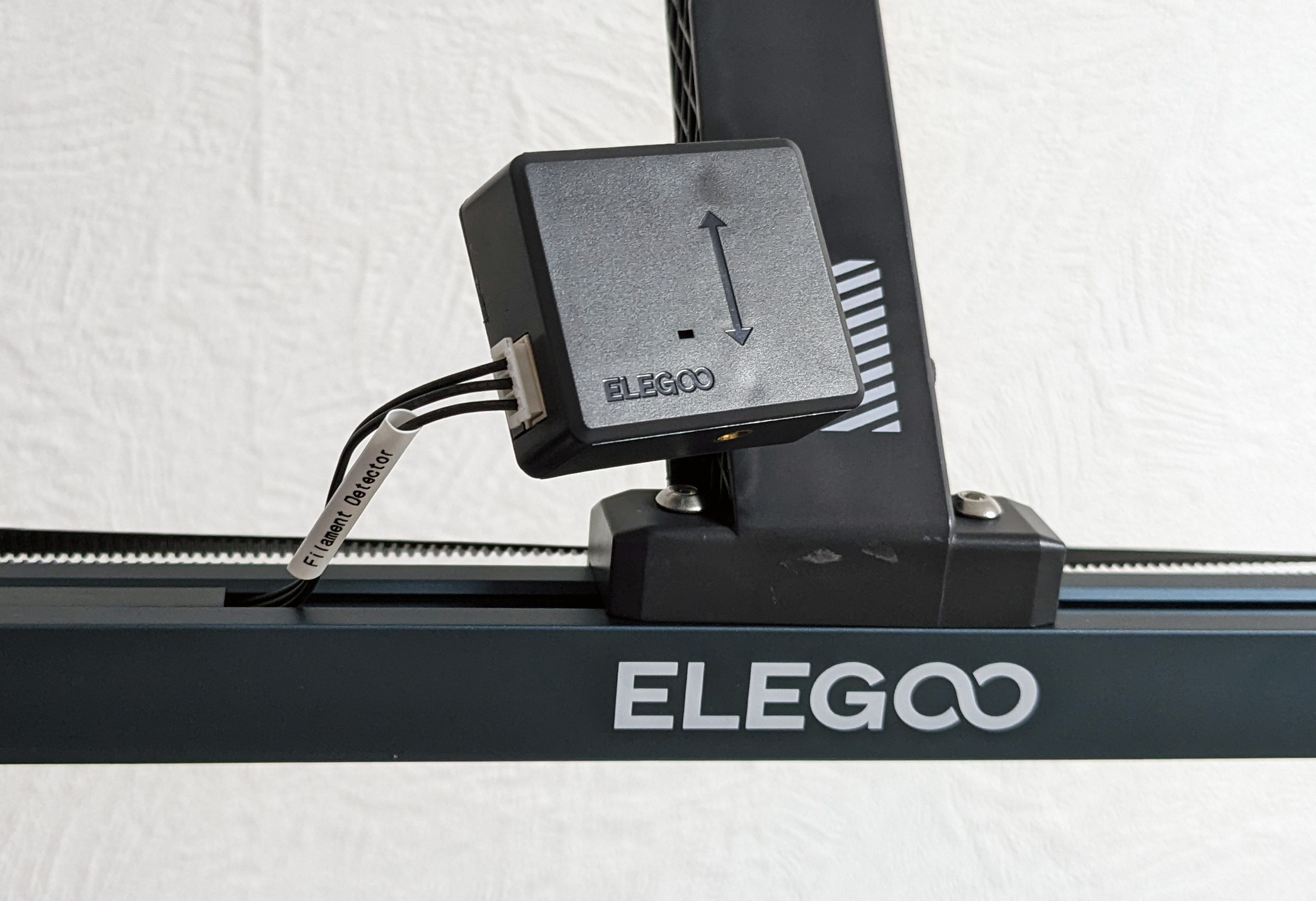
Theoretically, the filament sensor could be attached on both sides, but due to the short cable, it only works really well on the left side.
The connection cable to the extruder could almost make you nostalgic, as the ribbon cable bears a certain resemblance to the old IDE connections.
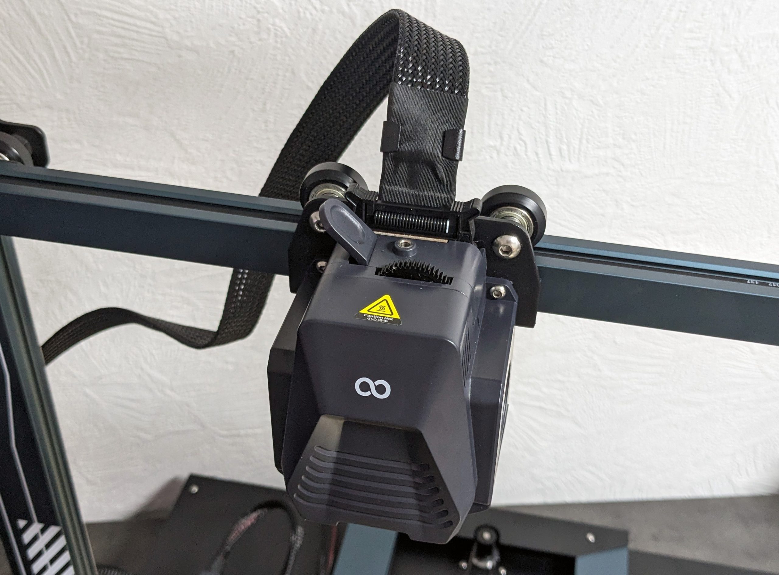
To prevent the cable from getting in the way during printing, it is fixed in a holder on the side.
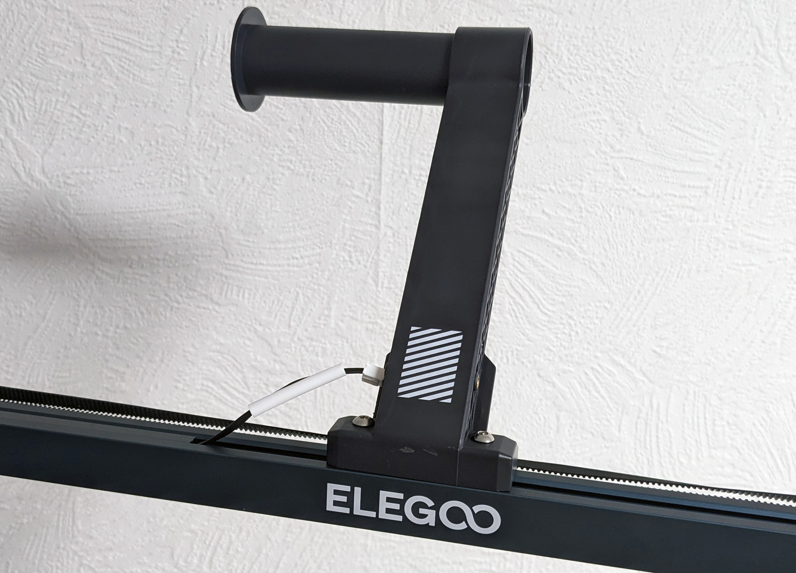
Due to the considerable height, additional stabilization is required, here in the form of two long rods.
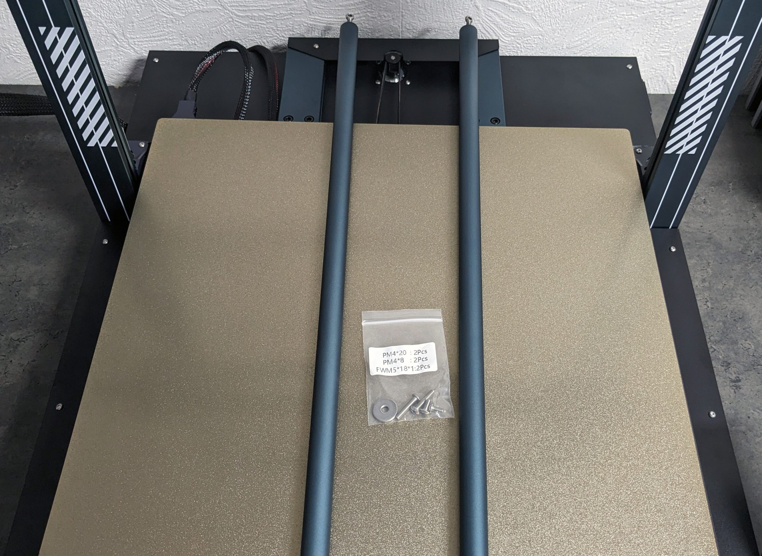
There is a corresponding holder at the top, into which one end is loosely attached with a screw.
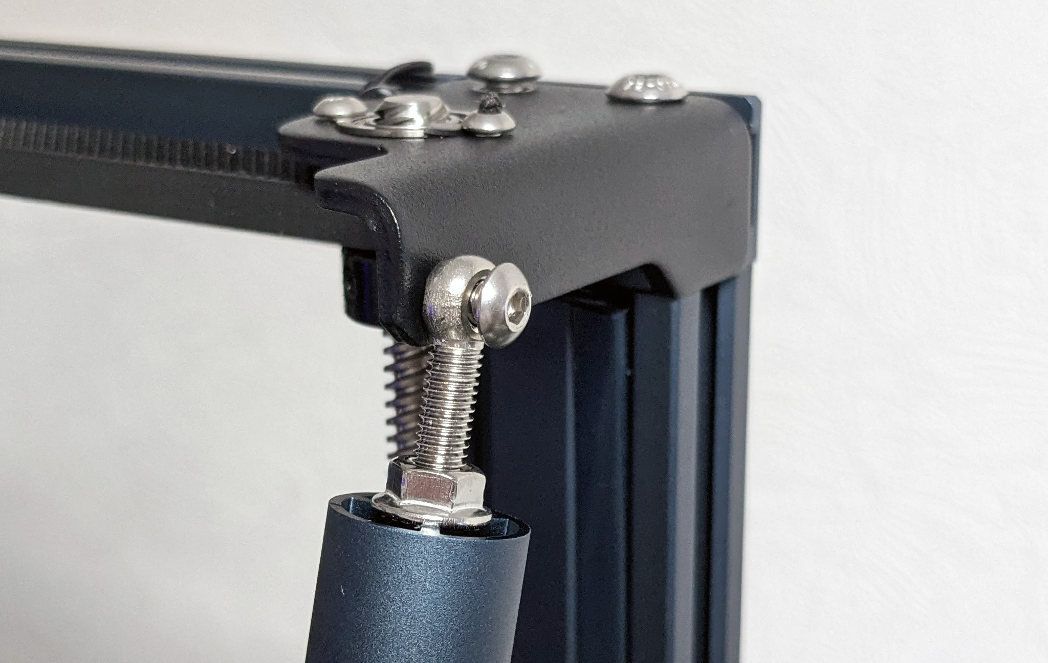
And at the other end there is a somewhat hidden thread.
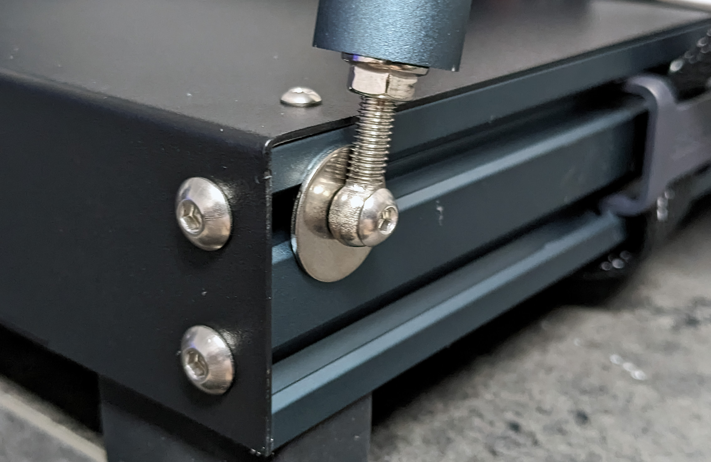
Reinforced in this way, the structure really does look much more solid and turning it back and forth is also somewhat easier.
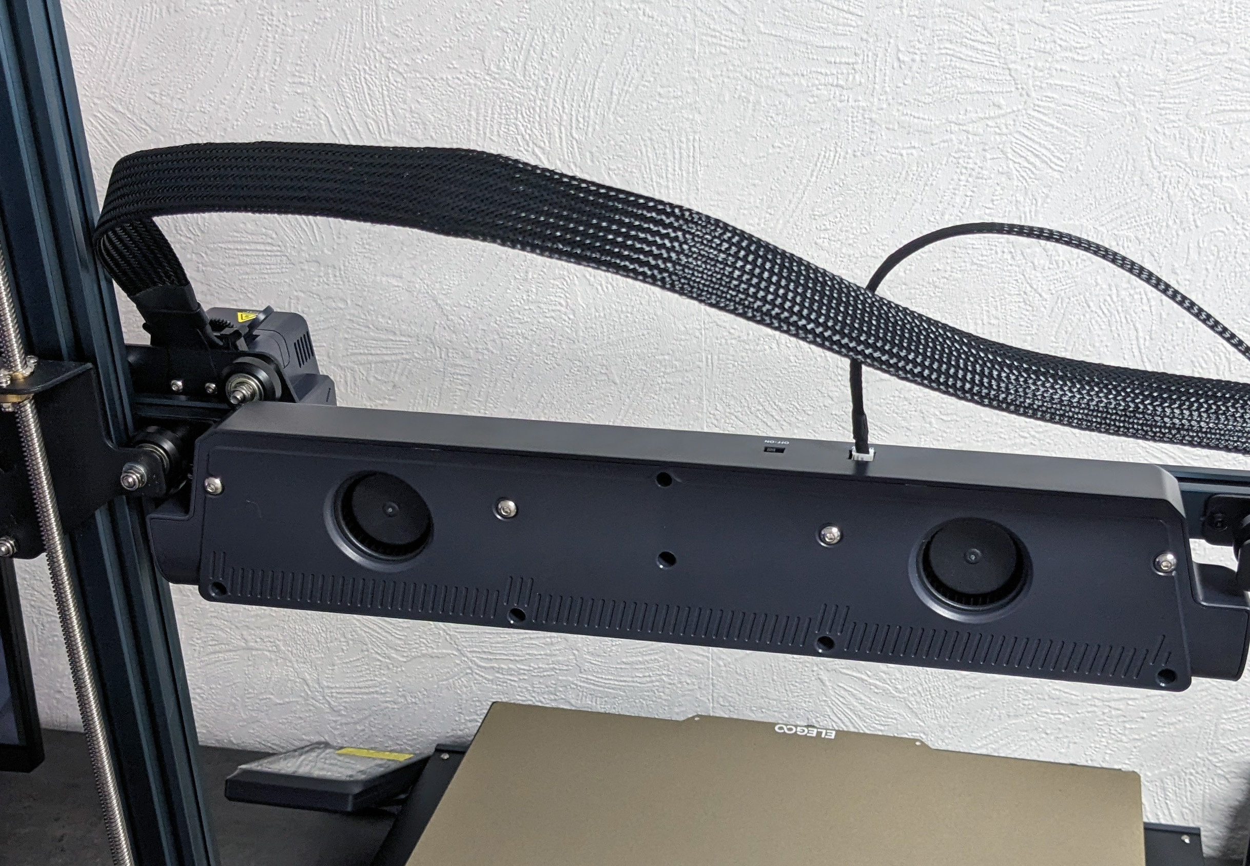
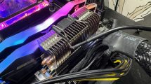
One of the hallmarks of the Neptune series of 3D printers is the large external cooling system, which is also used here. Just bigger again.
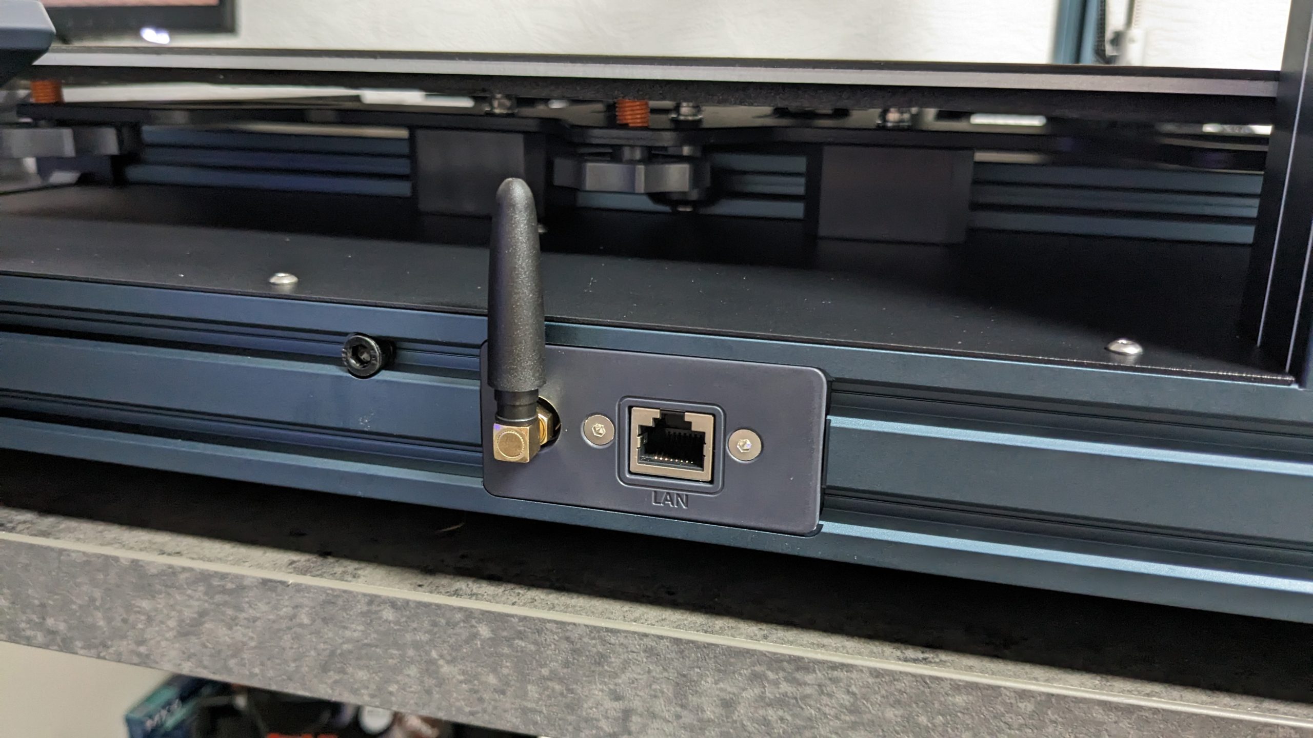
But now let’s move on to the little things, such as the WLAN antenna right next to the LAN connection. The lack of WLAN was a problem for many buyers of the normal Neptune 4, but now it has been retrofitted.
Just connect all the cables and you’re done.
The Neptune 4 Max is really unwieldy and also heavy, so the assembly is also somewhat cumbersome. Everything can be done on your own, but don’t underestimate the bulkiness and weight.


21 Antworten
Kommentar
Lade neue Kommentare
Mitglied
Moderator
Urgestein
Veteran
Moderator
Veteran
Moderator
Veteran
Neuling
Urgestein
Moderator
Urgestein
Urgestein
Urgestein
Moderator
Urgestein
Moderator
Urgestein
Urgestein
Alle Kommentare lesen unter igor´sLAB Community →