


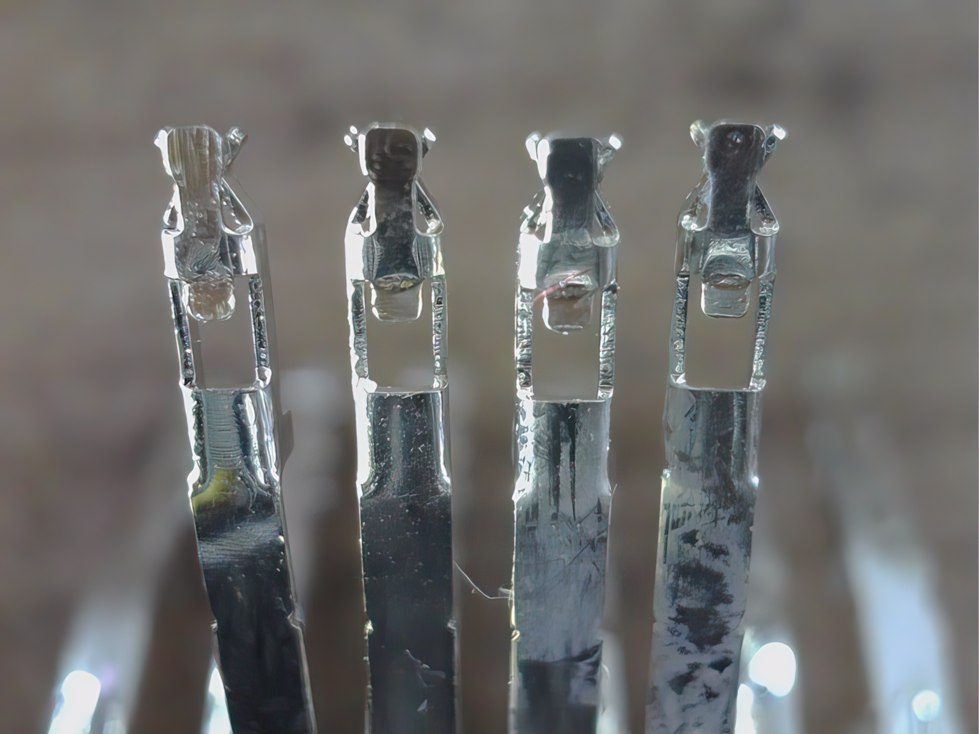
The most important thing: contacts in the connectors of the adapters and the terminal
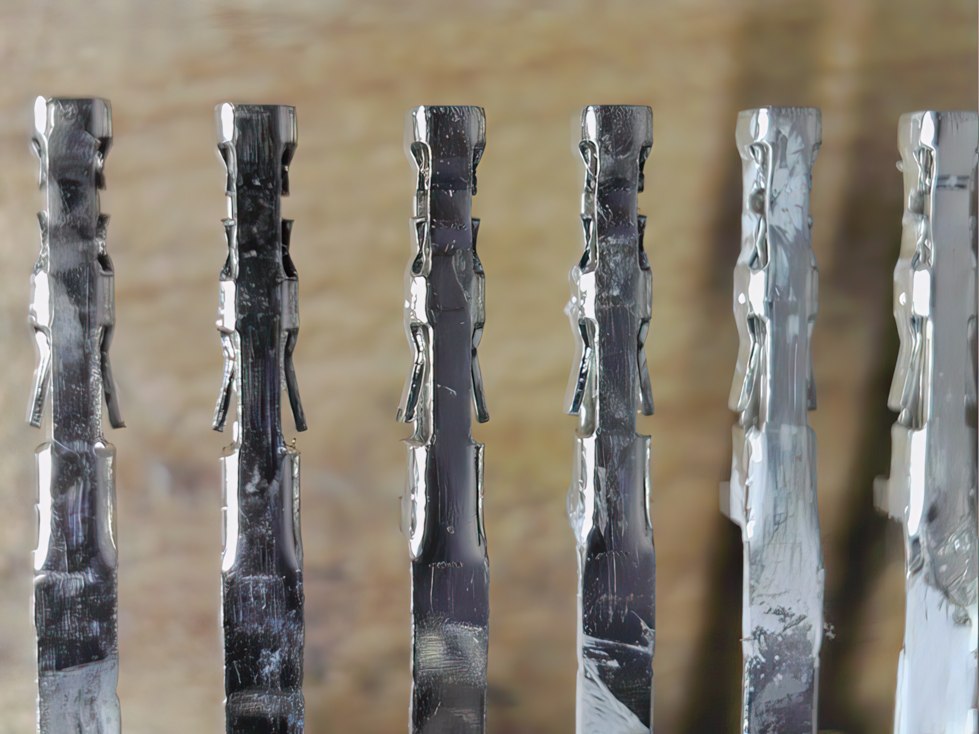
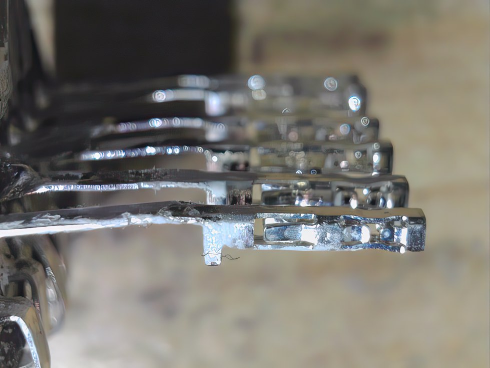
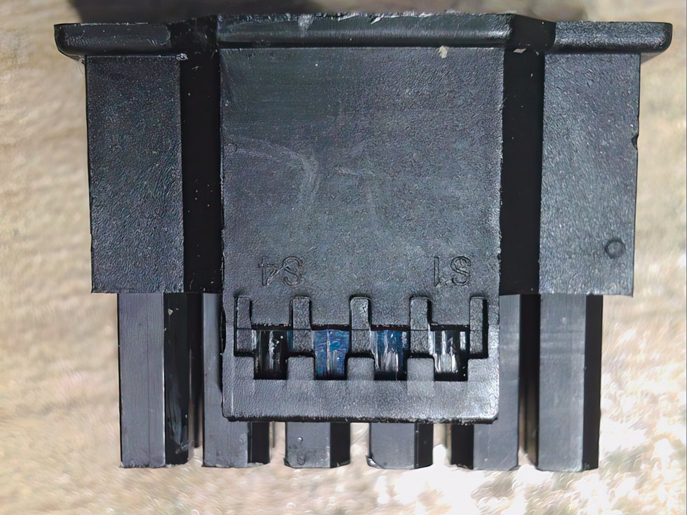
Before we look at the undamaged specimens, I destroyed one of the prototypes for you to show you the inner workings of such a terminal. The twelve contacts used for the power supply are simply slotted and have a “4- Spring” design. I won’t say “Tulip” design in the following either, because it probably sounded too poetic to the standardizers. Too bad, because it was actually the more beautiful term…
The ATX 3.0 specification states “Thermoplastic Glass Fiber Filled, UL94V-0” as the material for the terminal that houses the contacts. Glass-filled plastic (polymer) is a moldable and highly durable composite material. It usually consists of short glass fibers in a matrix of a special polymer material adapted to the application. It can be used by injection molding or compression molding and obtain a component that electrically, thermally and chemically meets the requirements.
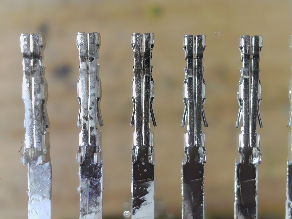
CableMod’s product already uses the new iteration of plugs and sockets, whose sense pins are slightly set back so that there is only an OK signal when the plug is engaged, i.e. inserted far enough. This also deprives certain YouTubers of the chance to generate profitable content again with completely incorrectly inserted plugs on purpose and to portray third parties as stupid. I think this is a very important feature, but it’s not everything.
The sockets, if soldered perfectly, sit directly and cleanly on the adapter’s PCB. With this, the physical peculiarities of the plug contacts and the terminal are also clarified and we can now turn to the rest of the adapter construction.
Internal structure: circuit board, bridges, pad and cover
The heart of the adapter is the built-in circuit board. In the end, I was able to convince CableMod not to go with the normal 35 μm copper thickness boards (1 oz / ft2) and soldered-on voltage rails, but to go straight for the ones with double the copper thickness of 70 μm (2 oz / ft2). Since IPC-4562 specifies that the base copper (i.e. before processing) may be a maximum of 10% less than specified, it is not at least 31.31 µm, but twice that. After the actual processing, a final copper thickness (IPC-A- 600J class 2) of at least 55.7 µm remains instead of the 24.9 µm of normal blanks. That would be a bit thin in the long run and for overclocking fanatics. Better safe than sorry, and even better.
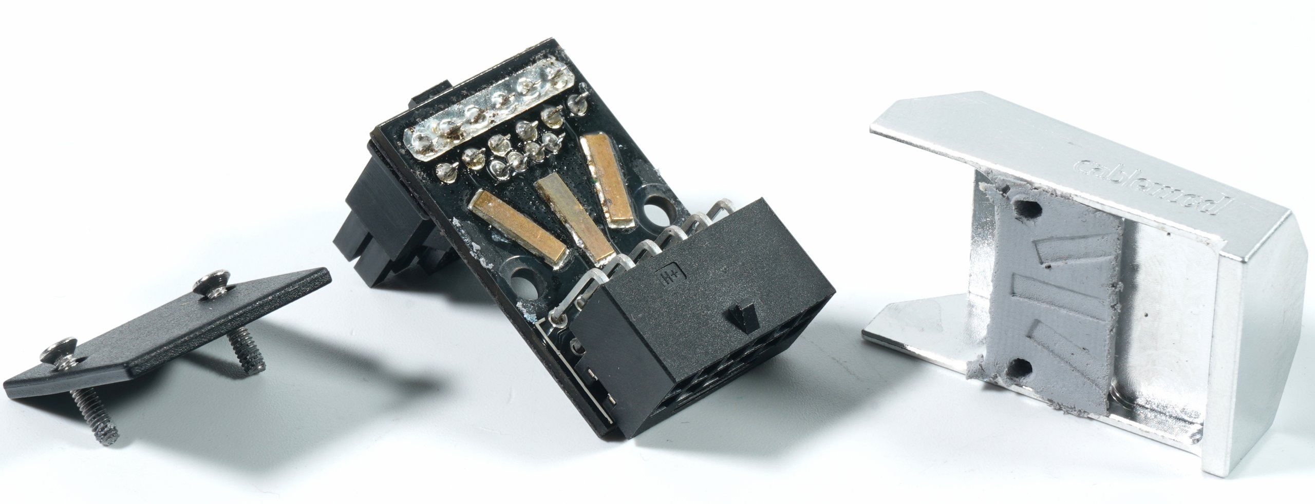
We can also see the three additional copper bridges that reinforce the three 12V strands on the board (3 x 2 pins) as a precaution. It is therefore necessary to know that two pins are electrically combined in each case. This is not only for layout reasons, but also for safety reasons, in case one of the six 12V strings should fail externally (which of course one does not hope for). The cover is made of cast light metal, which has been finished inside with a CNC milling machine to shape it.
Aluminum is a good heat conductor and we will see in a moment how useful it is to thermally bond the PCB and especially the 12 volt bridges directly to the solid case using a good, non-oiling and 1.5 mm thick thermal conduction pad. However, anyone who touches the case with their fingers after using the graphics card for a longer period of time should be careful, because the surface temperature also roughly corresponds to the temperature of the connectors and PCB including the three bridges inside. By the way, this is not a flaw, but a deliberately constructed and calculated feature. Only you have to know that (manual and sticker).
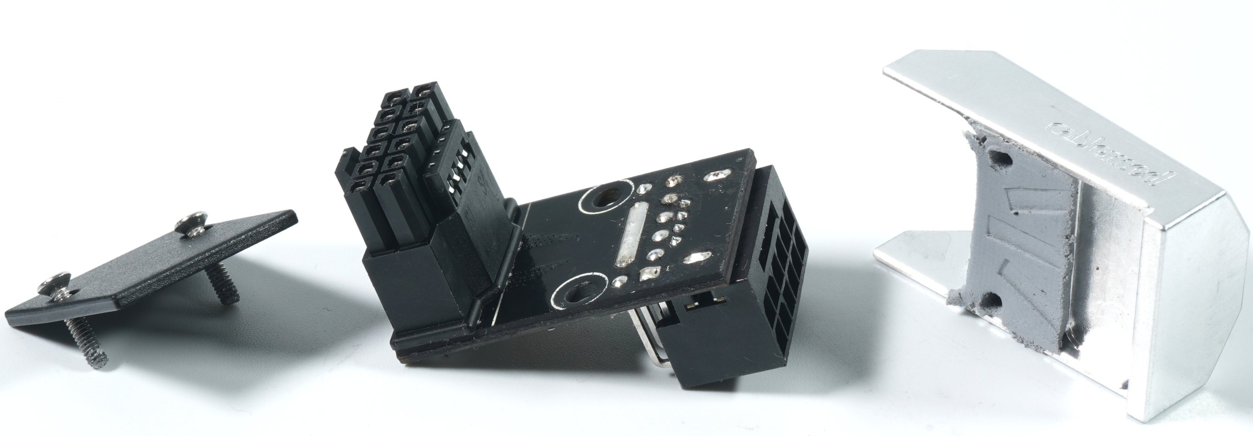
Since the board as a whole can get quite hot (especially with air-cooled cards), CableMod uses polycarbonate instead of ABS for the base plate, i.e. the cover on the card side (which also carries the screws in the picture above). This is an engineering thermoplastic, which in our case is characterized by high heat resistance and good impact strength. Theoretically, this is also available in transparent, but I’m sure no one wants that.
This also clarifies the adapter plugs, whereby the 180° adapter hardly differs from the 90° adapter. Therefore I save the redundant description, because the second connector has been soldered only standing and not lying. The rest remains more or less the same. But how does the part perform thermally and electrically now? Let’s move on to the measurements and the radiometric images. Turn the page again please!


568 Antworten
Kommentar
Lade neue Kommentare
Urgestein
1
Urgestein
Mitglied
Veteran
Urgestein
Mitglied
Urgestein
1
Urgestein
Veteran
Urgestein
Veteran
Urgestein
Urgestein
1
Veteran
Mitglied
Mitglied
Alle Kommentare lesen unter igor´sLAB Community →