


So now we would have reached the power supply and want to deal with the problems that can await us on the secondary side of a modern power supply. However, since I am not writing a power supply article, but a graphics card article, I have to pre-sort the content of the product. In addition to the actual working principle, I am therefore only interested in the secondary side and in particular the task and the placement of the so-called secondary capacitors and the eternal discussion about the design of the rails. For this purpose, I now use – with some intent – a digital 860-watt power supply of the upper middle class and have rounded the measured voltage values slightly to keep the graphics a little clearer.
12 volts are not equal to 12 volts!
A current ATX power supply is based on the principle of a switching power supply, which in itself is not a bad thing, as long as the voltage generated in the switching processes is sufficiently smoothed afterwards. If one looks at the 12-volt line provided in the power supply with a suitable oscillograph, then the expected constant DC voltage of 12 volts becomes a kind of alternating voltage mixture, the mean value of which is of course exactly within the framework of the ATX specifications. But only the average!
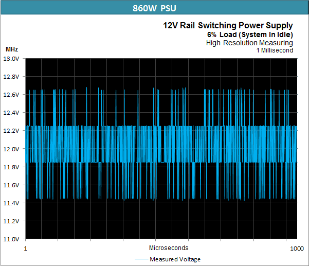
Now let’s look at the almost loadless state of a digital power supply that operates at a slightly lower switching frequency. The smoothing is quite acceptable, even if we see here with higher dissolved measurement that there are no constant 12 volts available, even if the average value for the entire millisecond is quite exactly 12 volts. In the end, the whole thing is nothing more than a residual ripple.
But what happens when peak loads now hit the already “pulsating” secondary side? We can see in the following graph that even in this situation the ATX specifications are still being adhered to – at least as long as the mean is concerned. If we look at the measured millisecond, we end up with an average of about 11.85 volts.
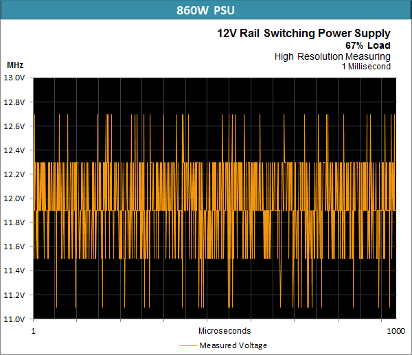
The pulse-like charged capacitors of the secondary side therefore meet rather wild spikes, whose frequency can be almost twice as high as the switching frequency of the power supply. Often enough, it can happen that the next current peak hits a capacitor before it could even be fully charged again! We recognize this unfortunate encounter by the brief dips in tension down to approx. 11.15 volts.
In a rather whimsical test of two simpler power supplies with and without cable management, which were actually quite identical except for the KM board, as well as a rather nasty graphics card, which generates a lot of spikes, I came to a surprising conclusion at the time: I could see that the polymer capacitors additionally used in the modular power supply were able to cushion the tips quite neatly at the beginning quite neatly at the beginning. , if they are really well placed. On the one hand, the solids are much more nimble than the electrolytic capacitors and on the other hand, the required capacity can be much lower due to the short duration of the extreme peaks to still have an effect.
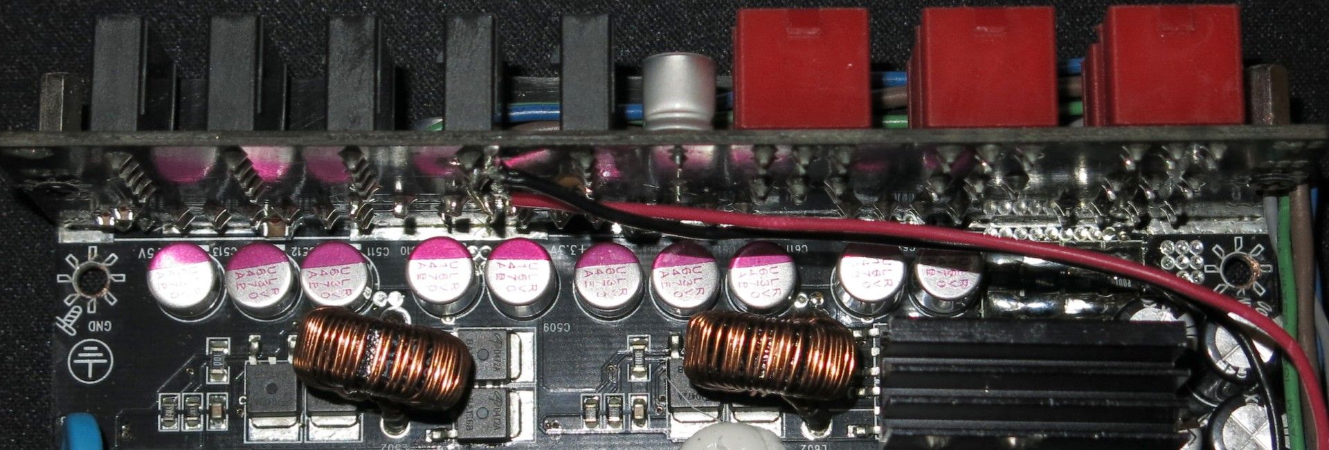
This should certainly have a positive effect on the durability of the actual secondary capacitors (pictured below), even if it is usually only an indirect consequence. For many power supplies, these polymer capacitors are primarily used to prevent, for example, the interactions between the main transformer and the vertically standing board occurring during the separation of the main and cable management boards. However, this side effect, which we observed and is very useful, is always welcome, even if it was certainly not thought of in this way with every power supply. Which would also make the arc to the actual electrolytic capacitor quite elegantly, about which there is still far too much ambiguity.
Low ESR, Low Impedance and Ripple
First of all, let us take stock. So what does a good secondary capacitor have to be able to do? It is designed to ensure that the power supply can continuously deliver high currents and also to ensure that load fluctuations can be absorbed. So far, so theoretically. But Elko (electrolytic capacitor) is not the same as Elko. And it is precisely at this point that it becomes interesting when we talk about the data sheet-related quality and the usefulness of the capacitor selection, which do not necessarily have to coincide!
Let’s go a step further now and wonder what such an Elko – also in terms of our wild graphics cards – should be able to do? For reasons of durability, it must first have the lowest possible internal loss resistance (ESR = Equivalent Series Resistance). This is why these so-called low-ESR versions are often found on the output side in power supplies or on motherboards in the area of VRM.
However, our measurements of power consumption, where the intervals of load changes sporadically follow each other even faster than the switching power supply can recharge the capacitors at all, make us think a little. Many manufacturers are now switching – certainly not without good reason – to very special low-impedance capacitors, where low internal resistances at high frequencies are involved, which standard Elkos do not offer to perfection. So much for expediency. But a little more later on.
Not only the capacity or the manufacturer’s imprint determine the optimal functionality of the secondary capacitors, but above all a very good high-frequency behavior (low impedance at approx. 100 KHz), a high speed when charging and of course also good Ripple values. I was able to find out again and again by evaluating the measurement protocols, where I also monitored the PowerGood signal, what happens when power supply deficits occur here.
As a result of these short-term voltage drops, it may happen that e.g. a chip installed on the motherboard for voltage monitoring on the corresponding pin sets the flag for the PowerGood signal to Low, so that the motherboard switches off the power supply and not the UVP or OCP/OPP installed in the power supply, because the required trigger values have not yet been reached!
The general problem with the protection circuits
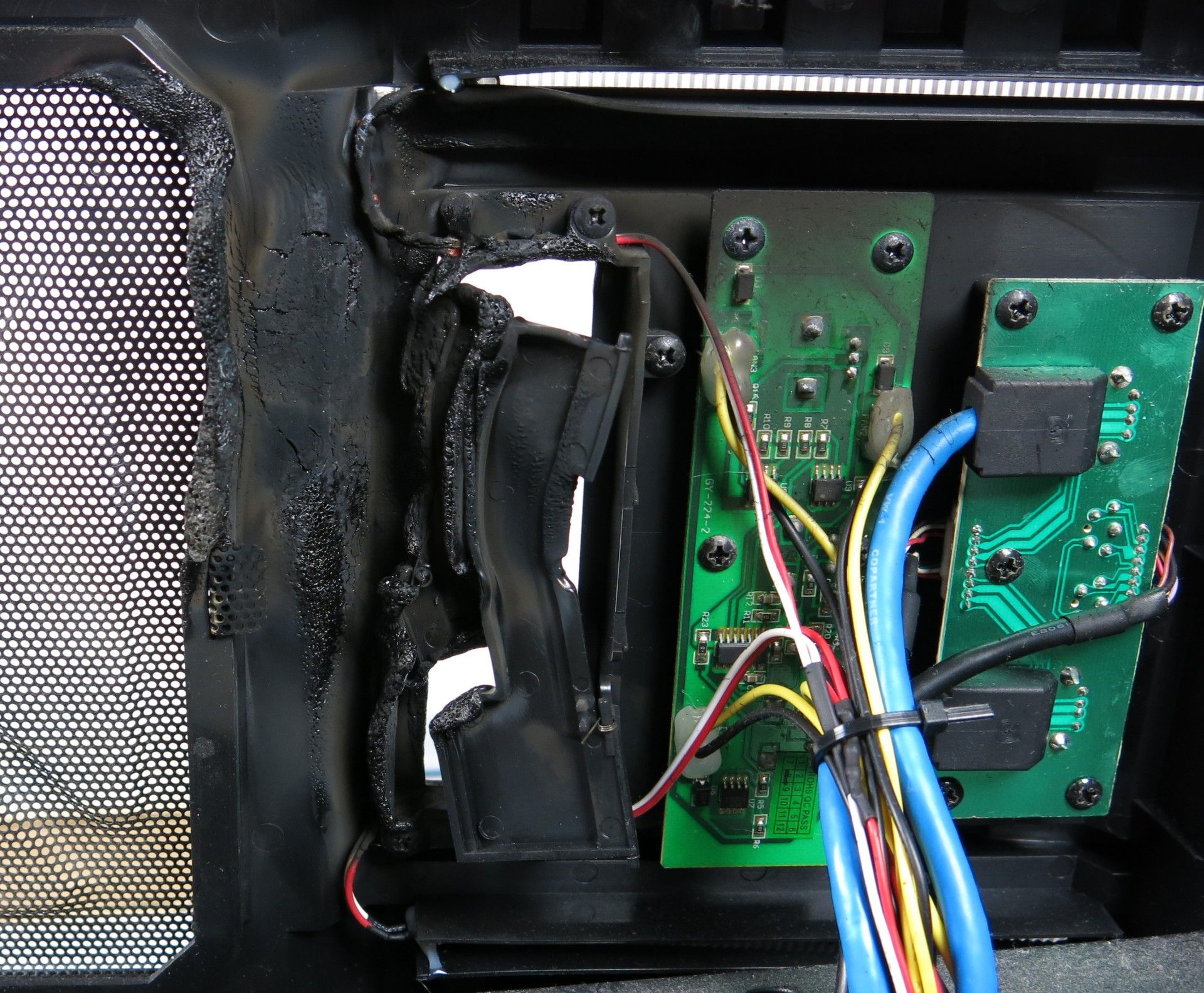
If there are shutdowns, even though the nominal load as an average value has not yet been reached, then the supervisor chips of the power supplies are either not appropriately chosen for this purpose (in the case of low-cost power supplies) or the response threshold and delay is much too low or. chosen too short. From the point of view of the power supply manufacturers, this is a tightrope walk, especially for very potent single-rail power supplies. Because what happens when, for example, so that a single-rail power supply is short-circuited and the cables on the SATA strand are far too thin to allow the required current to be passed for the response of the protective circuits, the following pictures show:
Looking for salvation in multi-rail circuits alone would surely also have jumped too short, as the current limits do not meet the requirements of the current graphics cards. We could plead for a PCI Express connector on 25 amps, as it could easily supply a cable with two 8-pin plugs. If you still need more, you have to use two rails with a single 8-pin plug. What is unfavorable, however, is that many supervisor chips that realize the OCP (overcurrent protection) in the power supplies can only secure up to 4 channels in total. This is not enough at the back and front if you want to secure the CPU and motherboard, as well as the entire drive connections separately. This is precisely where the digital power supplies, which offer a fairly flexible definition of the OCP per output, should take effect.
- Rule number one: Never oversize power supplies pointlessly! Always keep an eye on the total power required when choosing a single-rail power supply! In most cases, manufacturers offer up to 20 percent overload in the tips, which should not be exploited, but should never be left out of sight when relying on the protective circuits.
- Rule number two: Check multi-rail power supplies beforehand for the maximum load of the rails AND your own requirements! For example, if you if you want to operate a high-end card with 250 watts and more safely, you should use two separately monitored rails, which then also requires two individual PCI Express connection cables. With double plugs you usually can’t get any further. So pay attention to the cable assembly!
- Rule number three: Digital power supplies are a real asset to the market, but the quality of the regulation is important. Then it is especially important to have a suitable capacitor assembly of the secondary side, in order to be able to cushion all load peaks sufficiently.


Kommentieren