With up to three 8-pin connectors for current high-end graphics cards, the result is a cable-connector tangle that is slowly but surely reaching the limits of what is acceptable and sensible. The old 6+2 Molex connectors in this form are now technically simply obsolete. The 12-pin Microfit connector on NVIDIA’s Founders Edition was ultimately just a transition and owed to the “clear design” of the cards – it does not define a new standard, however, but remains a proprietary stopgap solution.
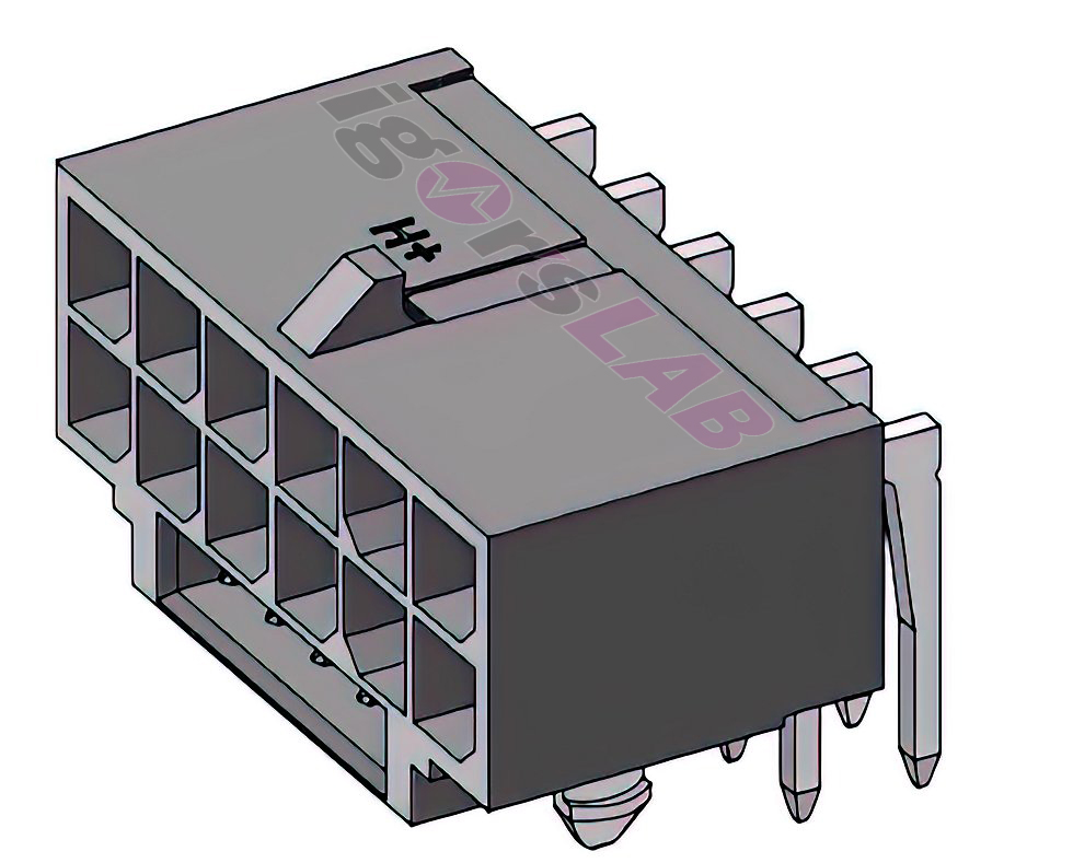
The 16-pin Microfit connector for the upcoming GeForce RTX 3090 Ti* that has been rumored on some websites does exist in the Molex universe, but it certainly won’t be standard on the whole cards. What NVIDIA will eventually put on the Founders Edition is still a secret, but that there will be a completely new plug is set and certain. Besides the power supply manufacturers I contacted, several graphics card manufacturers have already expressed some relief that the PCI SIG has also defined a new “High Power Connector” (H+) as standard within the specification for the new PCIe 5.0 standard. I have colored this new connector as a drawing for you myself:
The PCI Express 12VHPWR connector
Now let’s get into the details of the new power connection and cable assignment. This connector design was specifically defined to support cards with up to 600 watts of power consumption. This marks a new milestone, because in the end a current 8-pin connector is just a simple 6-pin connector, whose two sense pins should also only ensure that only those connectors are accepted, whose cables have been designed accordingly powerful.
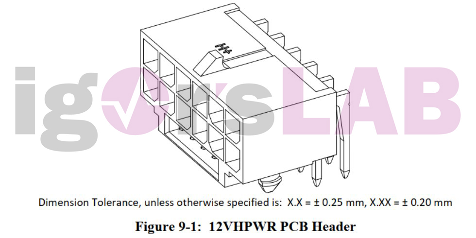
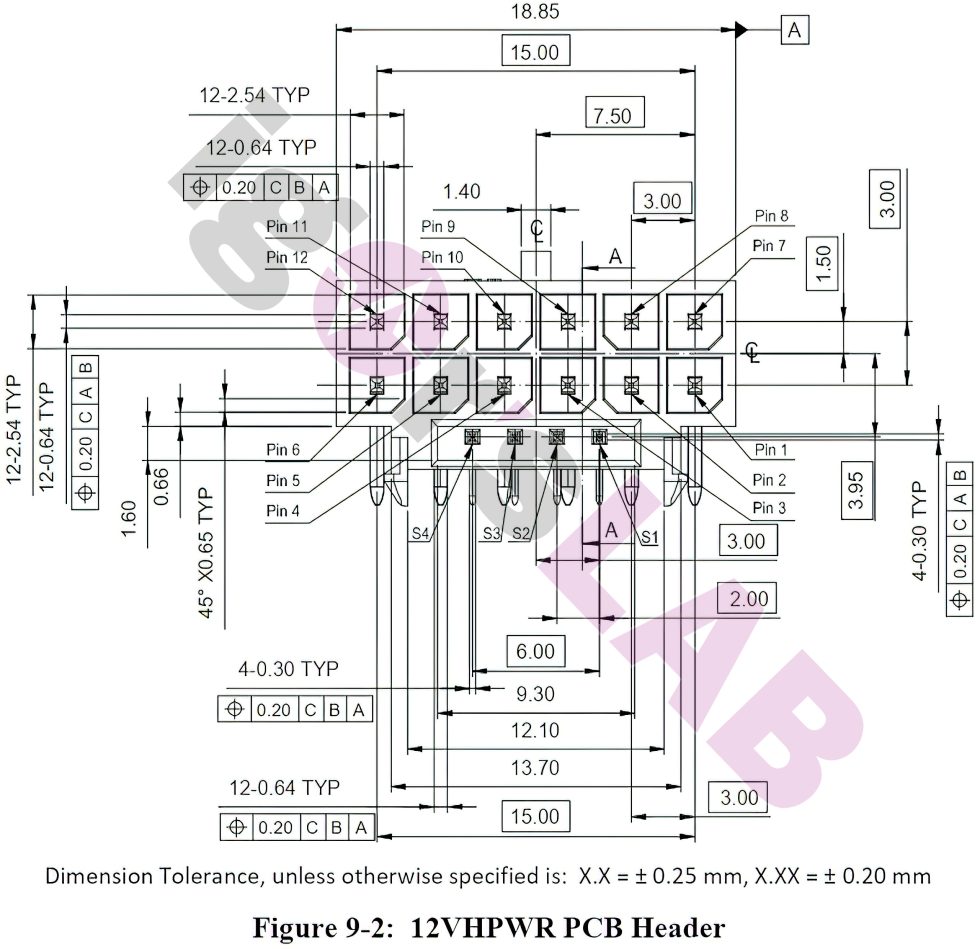
The new 12VHPWR connector therefore does not fit the PCI Express 2×3 and 2×4 Auxiliary Power connectors. The power supply pins of the 12VHPWR connector have a spacing of only 3.0 mm, while the contacts in the older 2×3 connector (6 pin) and 2×4 connector (6+2 pin) have a larger spacing of 4.2 mm. Figure 9-1 shows the unplugged 12VHPWR add-in card connector with through-hole. Twelve large contacts carry the power rail (2×6) and the four smaller contacts below are for the sideband signals.
Now let’s take a look at the technical drawing. We now also see why this new plug can supply so much more current without burning out right away. The 12VHPWR power connector provides up to 55A of continuous current to power the add-in card via a 12V power rail with a maximum power of 600W. The specifications to achieve this plug power are quite high. Let’s look at the drawing first:
The PCI SIG specifies a pin current capability (excluding sideband contacts) of 9.2 A per pin/position with a limit of 30 °C T-rise above ambient temperature at + 12 VDC with all twelve contacts energized. This results in 55.2 amps in one direction for the 12 volt power rail, or an even 662.4 watts. Of course, tolerances and safety deductions are still taken into account here in the total of just over 11 percent, so that in the end 600 watts can still be safely guaranteed
The connector body shall have a labeled or stamped H+ sign to indicate 9.2 A per pin (or greater) support. The approximate location of the mark on the 12VHPWR (R/A) right angle PCB strip can be seen in the drawing at the top. And to ensure that nothing slips out unintentionally, the inserted plug also has a locking mechanism that must be able to withstand at least 45.00 N when the plug is pulled axially.
What does all this mean for the graphics cards? The effort for sockets and plugs will be reduced enormously. In the future, a single, standardized plug will suffice for all cards here, as long as they need an additional supply connection and do not exceed a power consumption of 600 watts. It will significantly simplify the board layout and mechanical design, and this step is also long overdue. NVIDIA is the first to move forward here and will probably also push through the specifications for PCIe 5.0. However, it is still unclear whether the rumored RTX 3090 Ti will also support PCIe 5.0 on the data connector.
Bad times for cable modders?
The availability of the individual components should certainly be available for the circle of enthusiasts in the foreseeable future. However, according to one manufacturer, the processing is somewhat more difficult than with the simple Molex connectors. As a customer you will also have to pay attention to the correct cable cross-sections, but not only. With regard to the current carrying capacity of its individual cores, other factors come into play in addition to the pure cable cross-section.
In addition to the material used, the variants with different numbers of individual strands are also of interest here. The more individual strands are used, the thinner the cross-section of the individual conductors. This makes the cable much more flexible and therefore easier to lay. However, this also increases the electrical resistance and in turn reduces the maximum current carrying capacity. Below AWG 16 with a diameter of 1.29 mm (corresponds to a cross-section of approx. 1.31 mm²) I would not actually install anything. The 20 amperes of continuous load capacity possible here may seem completely overdimensioned at first glance, but you’ll definitely appreciate it in terms of efficiency. AWG 18 would also work if necessary, but then the material has to be really good. Cheap alloys are already ruled out here.
Let’s be surprised by the market, but the higher requirements (also with regard to the 4 additional signal lines) will separate the wheat from the chaff and many a hobby modder will probably prefer to look for another pastime or buy additional equipment.











14 Antworten
Kommentar
Lade neue Kommentare
Urgestein
Urgestein
Urgestein
Urgestein
Urgestein
Veteran
1
Urgestein
Veteran
Urgestein
Urgestein
Mitglied
Alle Kommentare lesen unter igor´sLAB Community →