


Such a sensor bar is neither mysterious nor difficult to recreate. In the meantime, various finished replicas are also available online for between 8 and 30 euros, but many tested products are not suitable for meaningful operation either due to underperformance or short running time. In addition, it is possible to better adapt a self-construction to the specific needs. Due to the more flexible use, we will build a cordless sensor bar that does not need an external power supply. Therefore, only two of the four possible infrared diodes are used to get by without battery replacement for as long as possible.
Material and tools:
- 2 powerful infrared diodes, 1.3 volts, min. 100 mA
- 1 to 2 battery holders
- 1.2 volt battery(s), size AA (R6), 2000 to 2700 mAh
- 1 simple on-off toggle switch (optional)
- Housing, wire, soldering iron (25 watts), fine solder and flat pliers
Cost of our sensor bar without batteries: 4.92 Euro. The next graphic shows the schematic without pre-resistance:
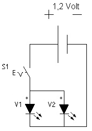
The right LED:
For simplicity, we have deliberately selected diodes with 1.3 volt voltage for our project, as we can safely connect these diodes directly to the 1.2 volt battery without any pre-resistance. In addition, an output of at least 120 to 200 mW should be achieved to ensure safe detection even in large rooms at appropriate distances. The diodes are operated in parallel. If other diodes or voltage sources are used, then a suitable resistance must be used in any case! The calculation is very simple if the supply voltage, diode voltage and the maximum current of the diode are known.
Resistance = Voltage / Current
For example, if we use the 5 volt line of the USB port, our LEDs result in a voltage difference of 3.7 volts (5 volts – 1.3 volts). Since the diodes tolerate a current of up to 100 mA, the following calculation results from the
Resistance = 3.7 Volt / 0.1 Ampére = 37 Ohm
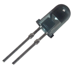
Infrared LED, the long connection is Plus
Attention: When soldering the voltage supply to the LED, the two connecting flags must be held with a flat pliers in order to dissipate the heat. Shortening of the connections should only be reserved for experienced hobbyists. The lower the melting point of the soldering tin used and the lower the power of the soldering iron, the safer the attachment of the soldering points.
Matching batteries:
Only batteries should be used as a power supply, as the running time is higher and also the environment and wallet are relieved. In addition, the slightly lower voltage allows direct connection without pre-resistance. In our solution, we have connected two batteries in parallel to double the running time. Since the current flow and the capacity of the batteries are known, the runtime can also be easily calculated:
Runtime = storage capacity / current flow
In our example with two batteries of 2700 mAh this results: runtime = 5400 mAh / 200 mA = 27 hours.
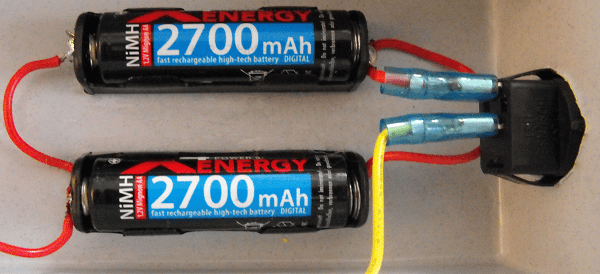
We see two parallel 2700 mAh batteries in the battery holder and the optional but useful switch. In principle, it does not matter which of the poles you provide with a switch. But a switch is more convenient than constantly removing and inserting the batteries.
Housing:
In this case, function and price went before beauty, as the goal was set to stay cheaper than the simplest Far Eastern junk products and still get decent performance. Because the limit was set at 5 euros and a flying wiring just looks ugly, a simple and cheap household box was used. The picture shows the finished sensor bar in use
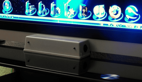
Depending on the room and application location or location, the distance between the LEDs should be Distance between Wiimote and sensor bar is between 28 cm (large room or auditorium), 22 cm (normal living room) or 15 cm (PC workstation at the desk). Here we first experimented and then decided on the 22 cm solution in the home area. Since you don't see with your own eye whether the diodes are working properly, a little trick helps. It is easy to check whether the LED is working with a digital camera or a photo phone, as the camera's sensors respond to the infrared light.


Kommentieren