


Board layout and components
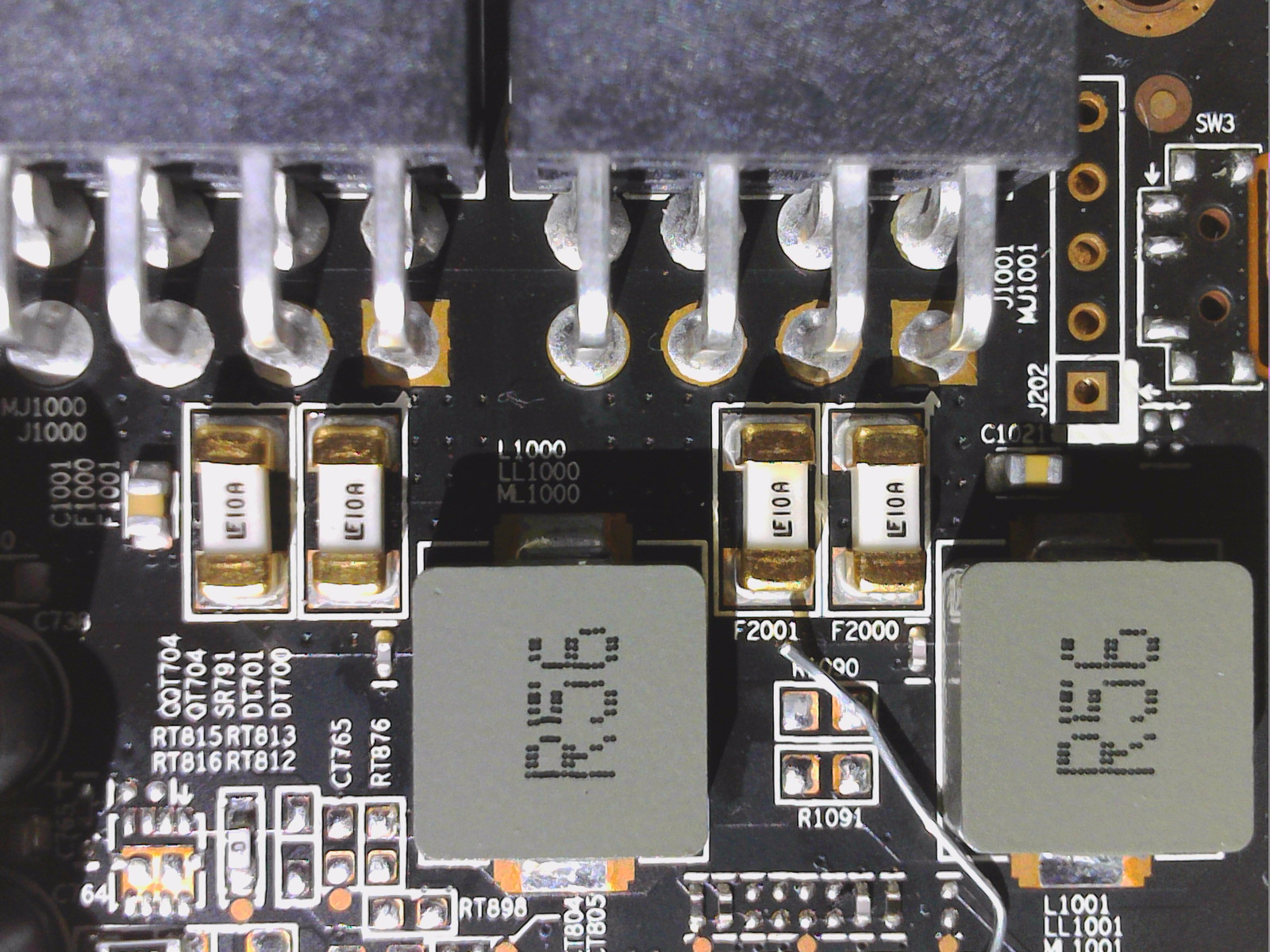
Once again, Sapphire has almost outdone itself with the PCB. Well equalized hotspots and a very thoughtful design with proper filtering after the PCIe ports and fuses, should on the one hand mitigate the load peaks on the power supply and on the other hand also increase the security of the overall system. Nobody really needs annoying RF waves from the graphics card. The 12V rails are fused with two 10 amp fuses per 8-pin input and one at the PEG.
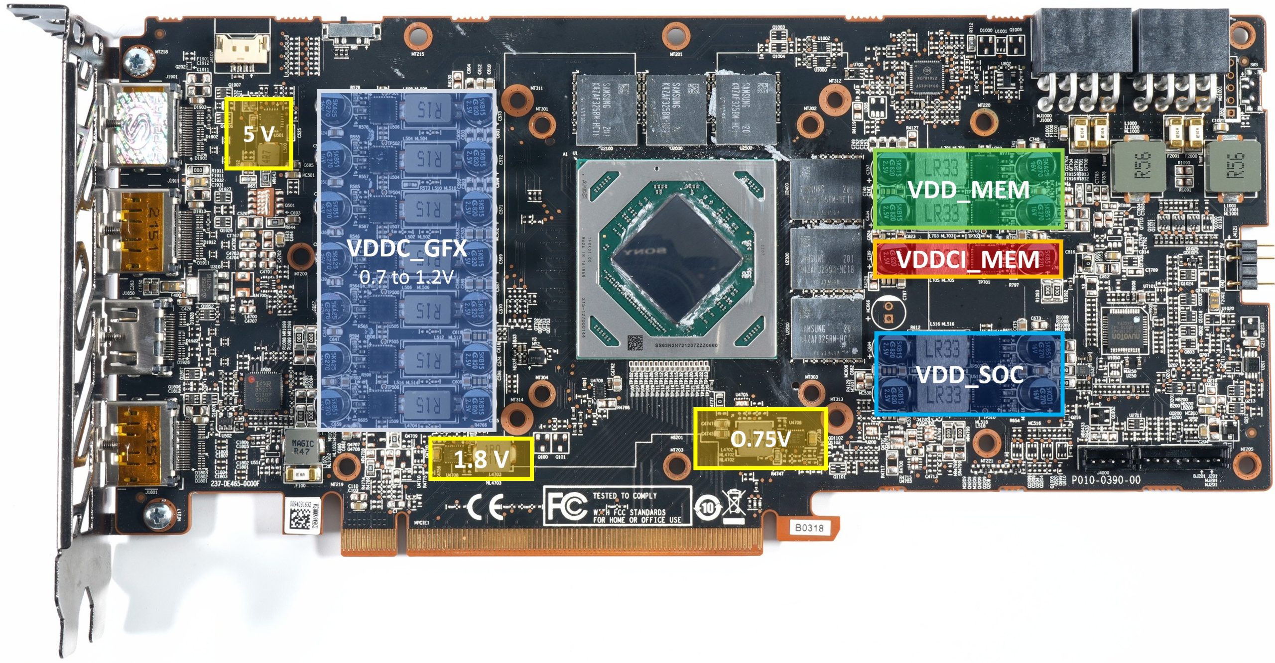
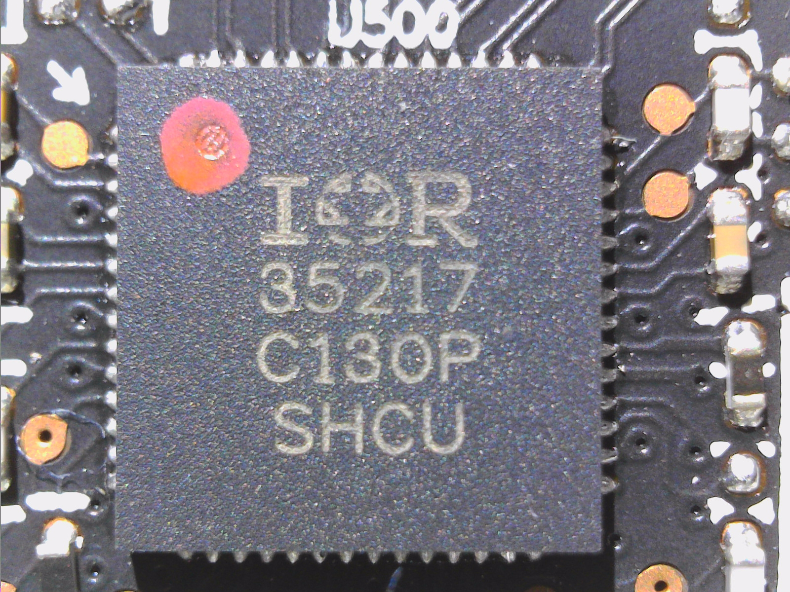
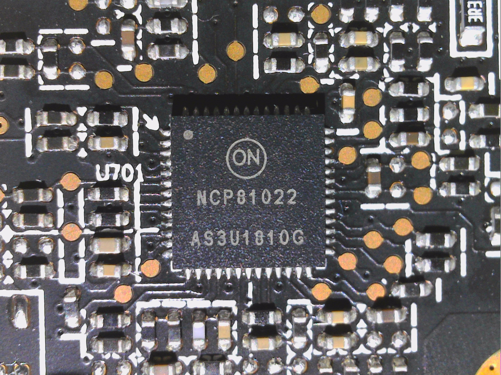
With an IR35217 from International Rectifier, one relies, like AMD, on a practical PWM controller, which drives the 7 phases for VDDC_GFX. Very good qualities are used for almost all important active components and the coils. A correct decision. In parallel, International Rectifier’s IR35217 also generates other partial voltage for VDDC_SOC. The 2 phases for VDDIO_MEM are handled by an inexpensive NCP 81022 from OnSemi.
In addition, we find another phase for VDDCI, so that in total there are 12 phases for the various main voltages, all of which work with one SIC649A from Vishay per phase as a Smart Power Stage. The IC contains a synchronous buck-gate driver IC in a co-package with Schottky diode, as well as the high-side and low-side MOSFETs. The combination of gate driver and MOSFET (DrMOS) enables higher efficiency at the low output voltages for the GPU and the desired DCR.
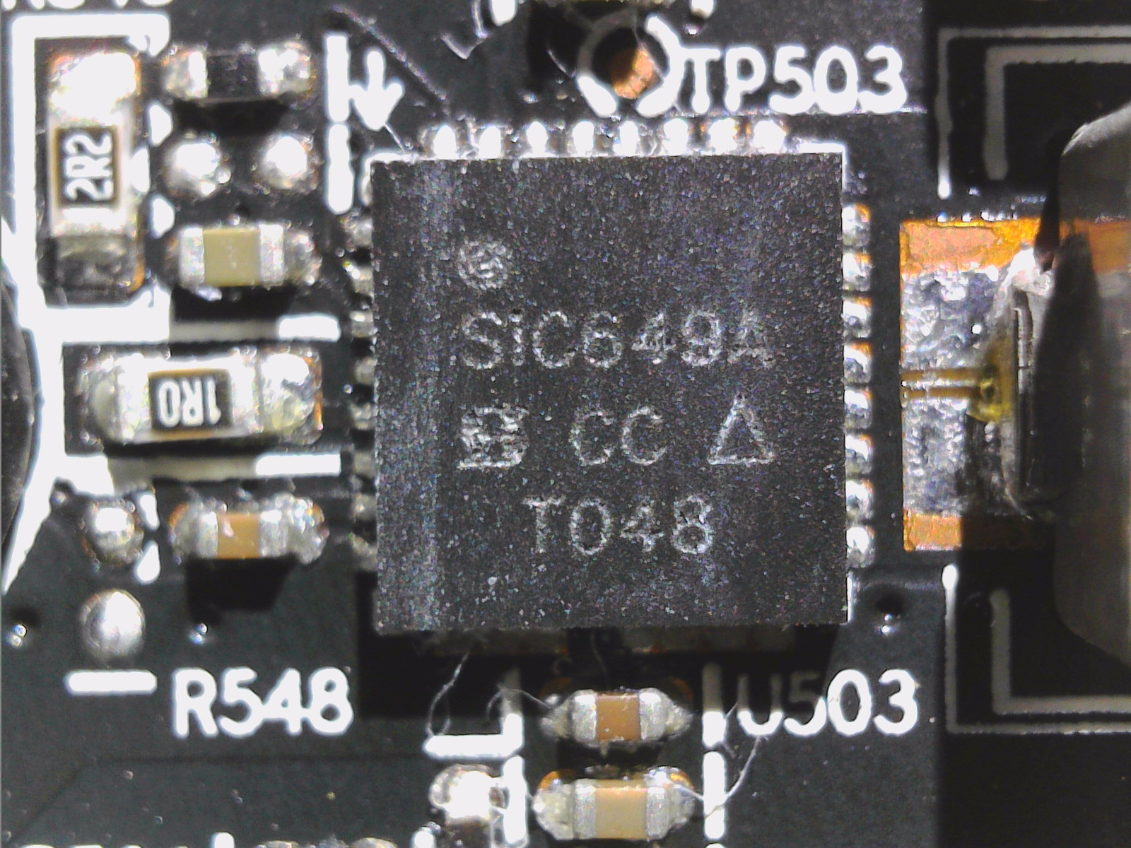
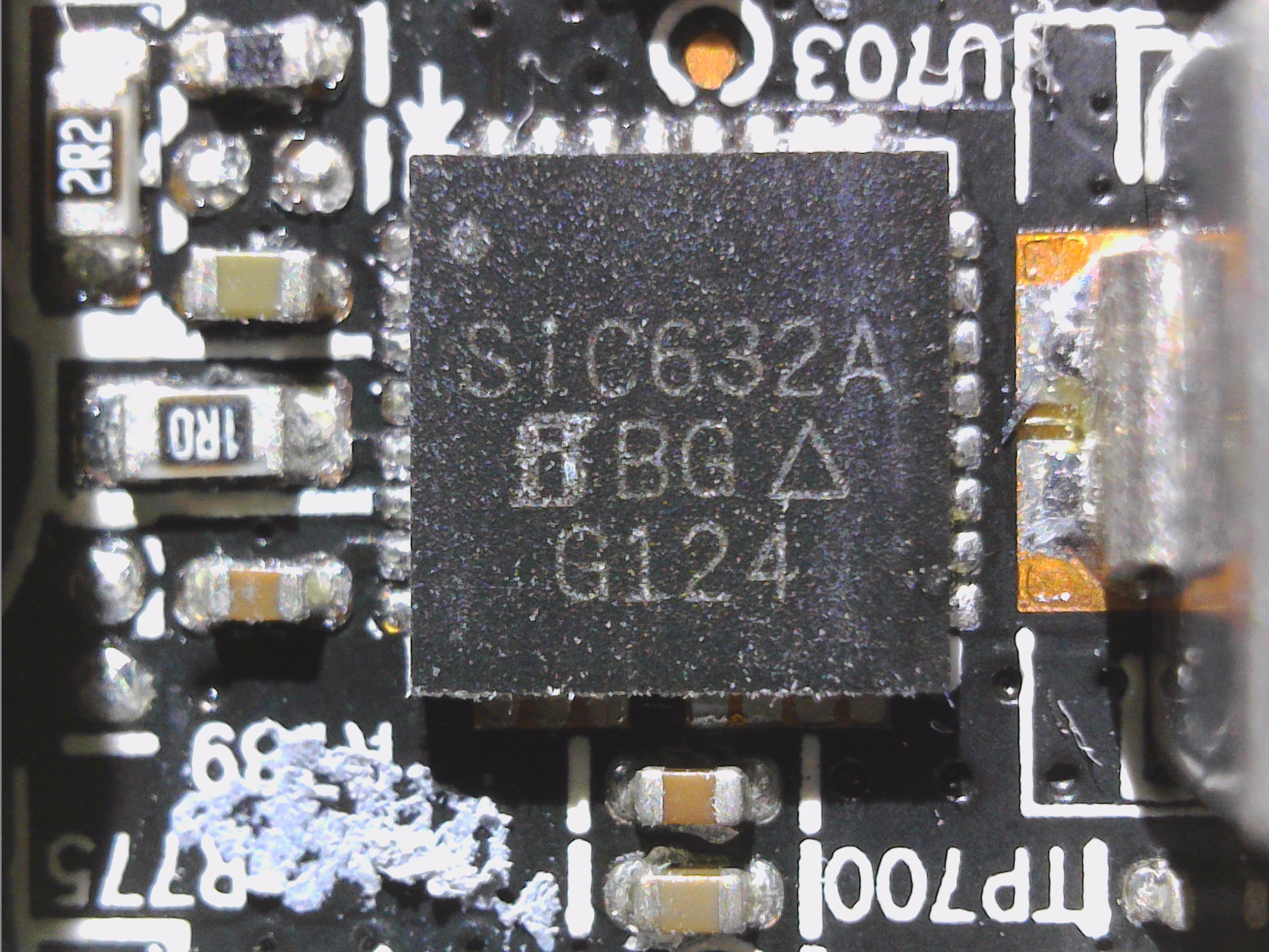
The internal MOSFET current measurement algorithm with temperature compensation achieves higher current measurement accuracy compared to the best inductor DCR sensor methods. Protection includes cycle-by-cycle overcurrent protection with programmable threshold, VCC/VDRV UVLO protection, phase fault detection, IC temperature detection, and thermal shutdown. The TDA21472 also features automatic bootstrap capacitor refill to prevent over-discharge.
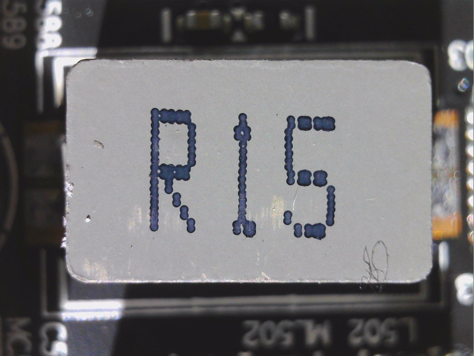
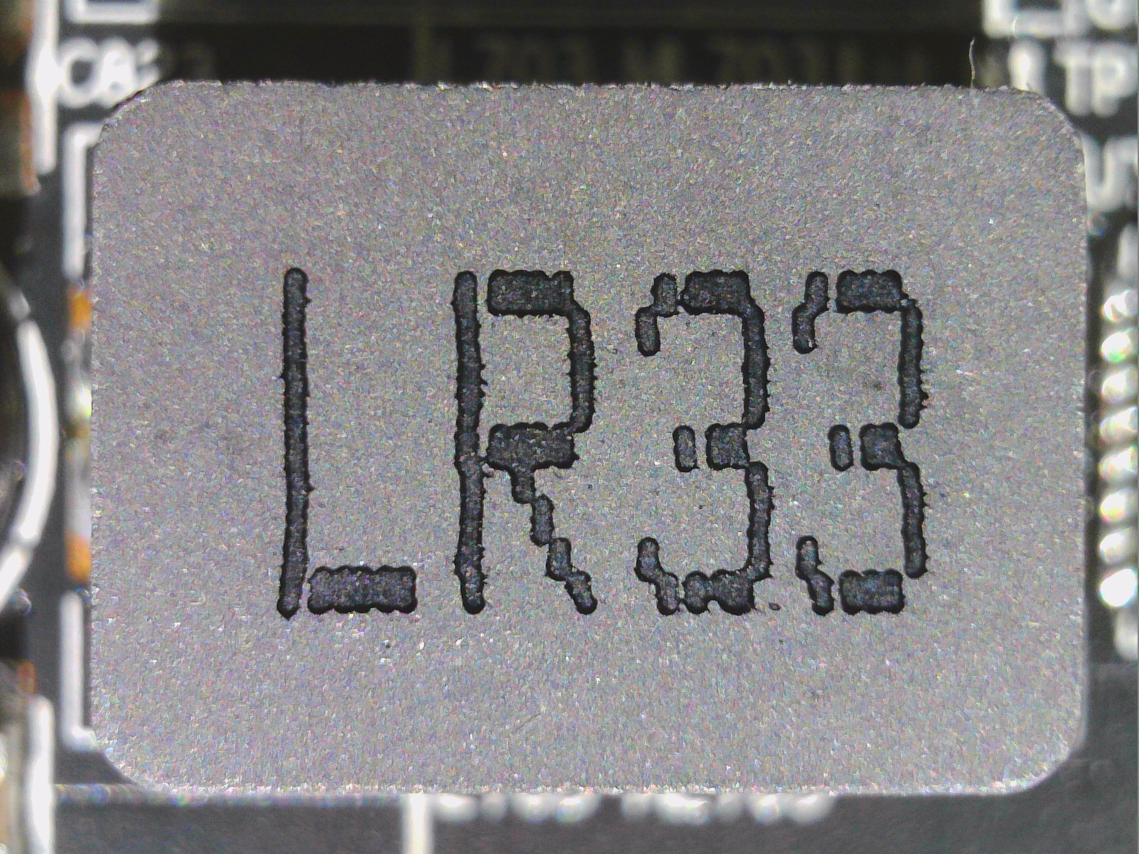
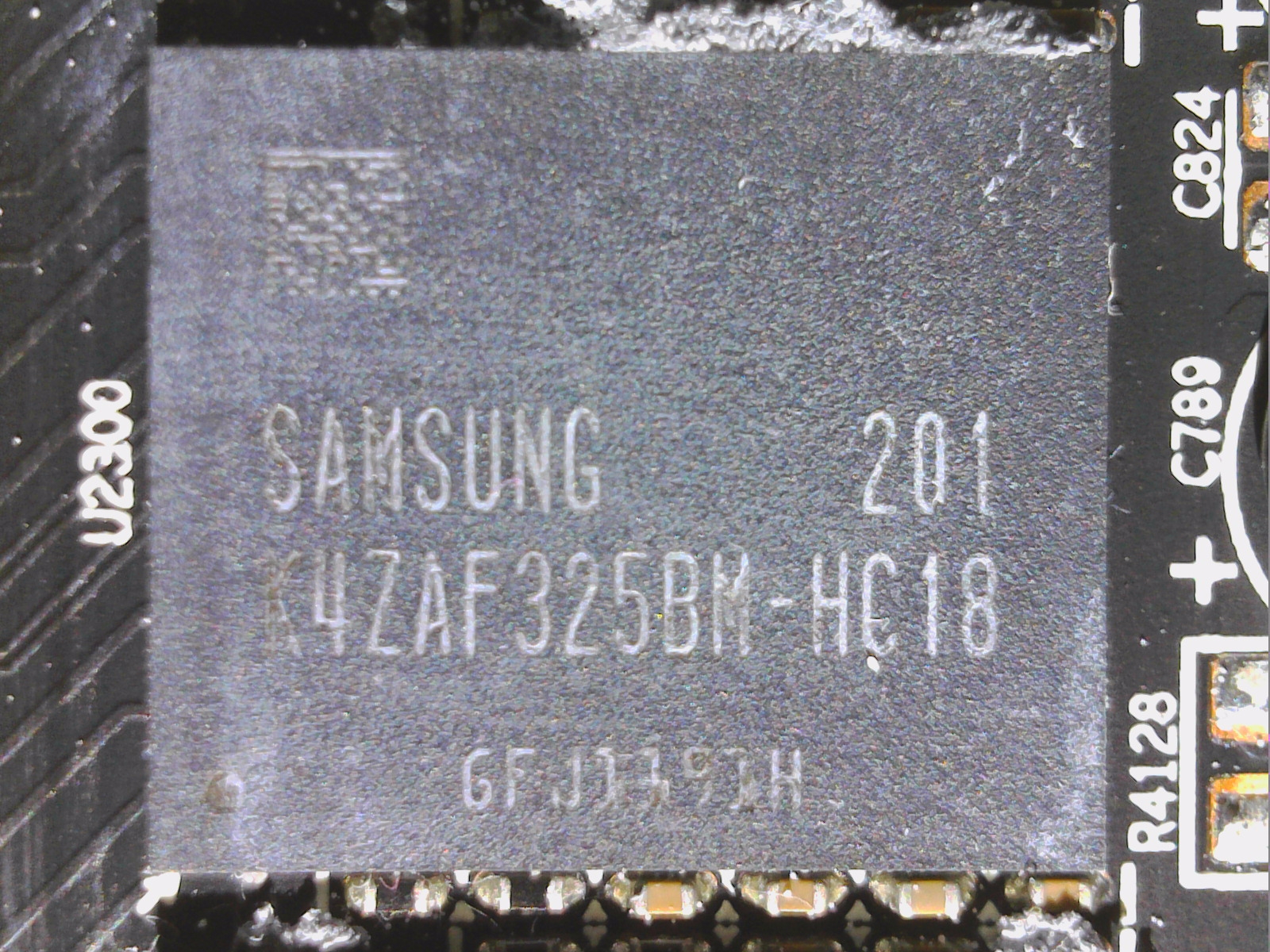
The coils used with 150 and 330 mH are quite decent and even buzz less than those on the reference card. Sapphire installs a total of 6 GDDR6 memory modules from Samsung with 18 Gbps. The back is quite tidy and you won’t find any SP or POS caps below the BGA. in general, everything looks very high-quality in large parts and otherwise at least very purposefully equipped. Instead of elaborate design stunts, the game relies on solid home cooking, which can really please. At the top there is still the connection for the aRGB diodes of the Nitro panel of the backplate
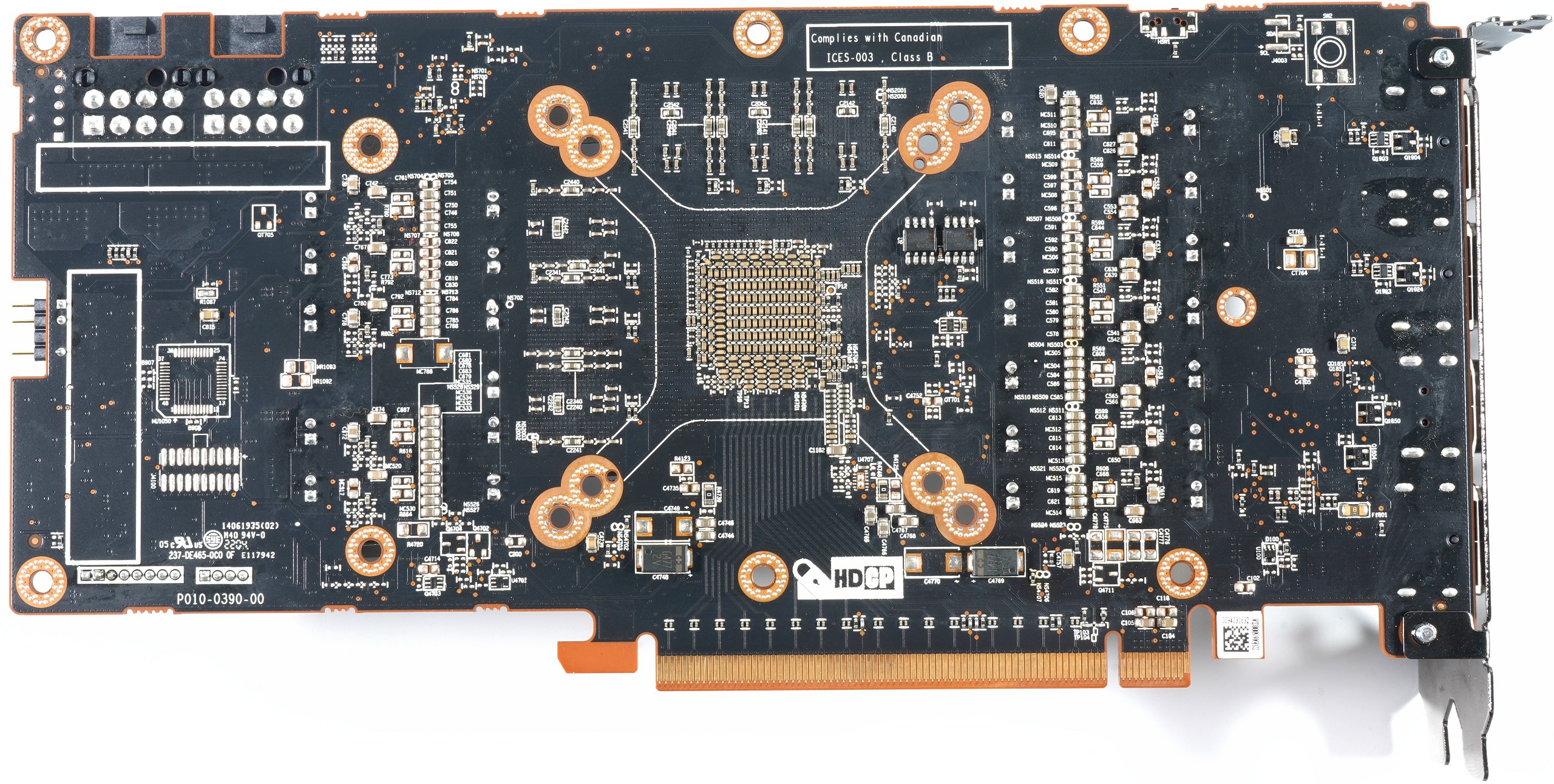
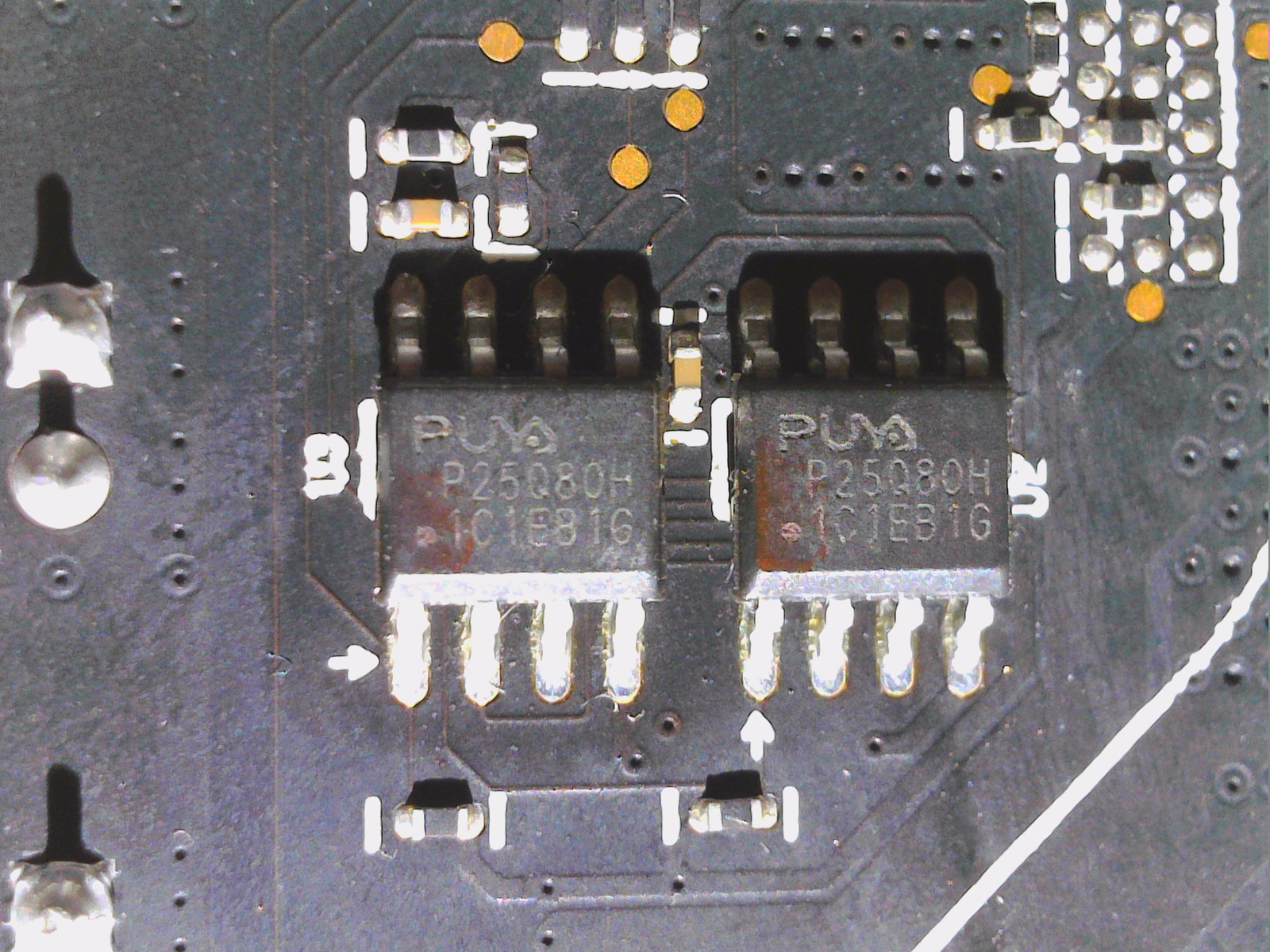
On the backside we see the chip for the dual BIOS and at the end of the board a Preci-Dip connector for the connection of the digital aRGB control. Another MCU from Nuvoton is located on the front for control and BIOS switching via software.
Cooler and backplate
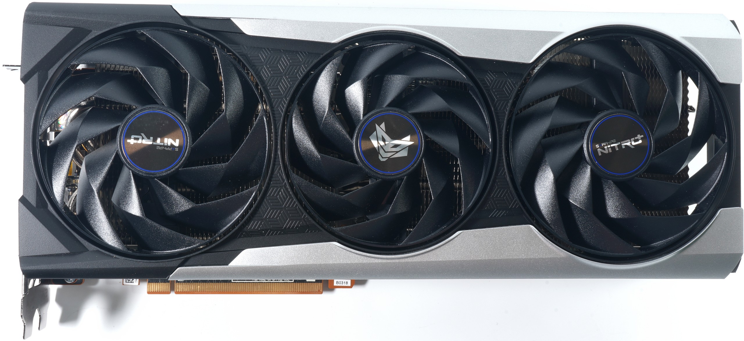
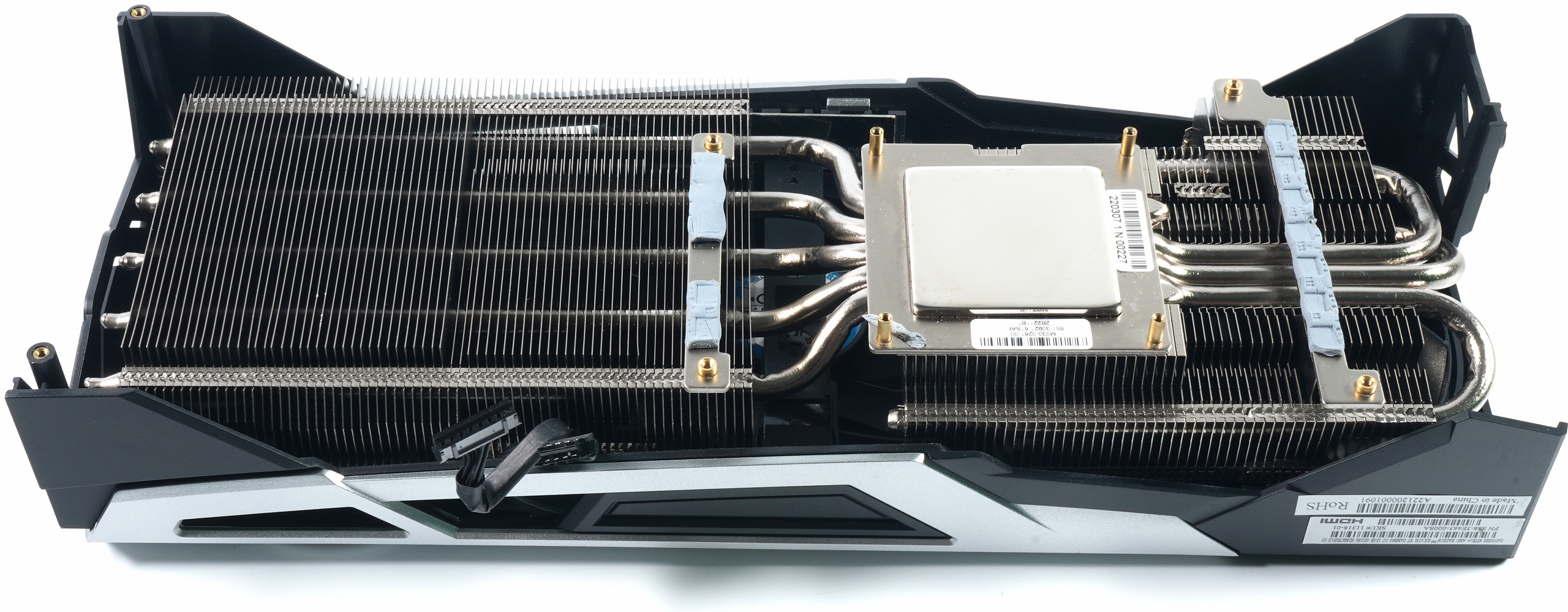
Sapphire relies on two 10 cm fans (9.5 cm rotor blade) and a 9 cm fan (8.7 cm rotor blade) in the center of the cooler, each with 9 rotor blades and an interesting rotor blade geometry. The design of the impellers is very reminiscent of special fans for very much airflow with intended vortices. Even though it is a 2.5-slot design, the very large gap of almost 2 cm between the cover and the actual fin heatsink is surprising here. This distance does not increase the cooling surface, but it ensures a much better and, above all, more even distribution of the airflow to all areas with fewer dead areas below the drives, because the distance between the fan and the cooler is greatly increased. And the metal part even becomes lighter as a result.
The cooler is divided into the rather massive and very long main cooler with five 6 mm heatpipes made of nickel-plated copper composite material, which were soldered to the heatsink flattened behind it. Three of the heat pipes are even recirculated to better supply the GPU-side cooler area with waste heat. The actual cooler is not directly connected to the frame of the cover, but is only enclosed by it and can move freely. This takes out any stresses that could be caused by GPU packages of different heights because the rest of the board is screwed tightly to the cover’s frame. The cooler itself is only held by the four screws including the retaining clip on the GPU socket and the four screws of the VRM heatsinks. Good decision!
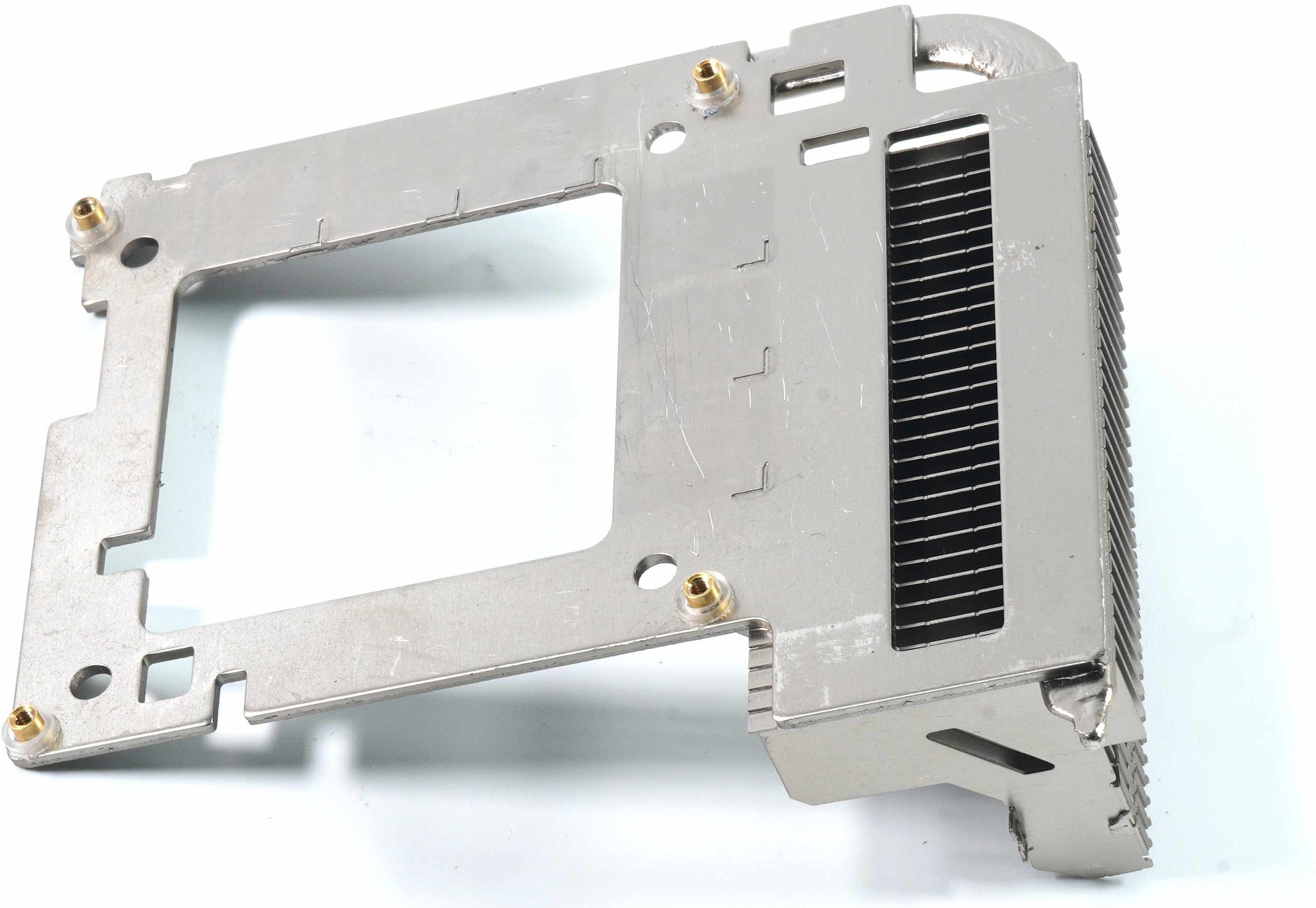
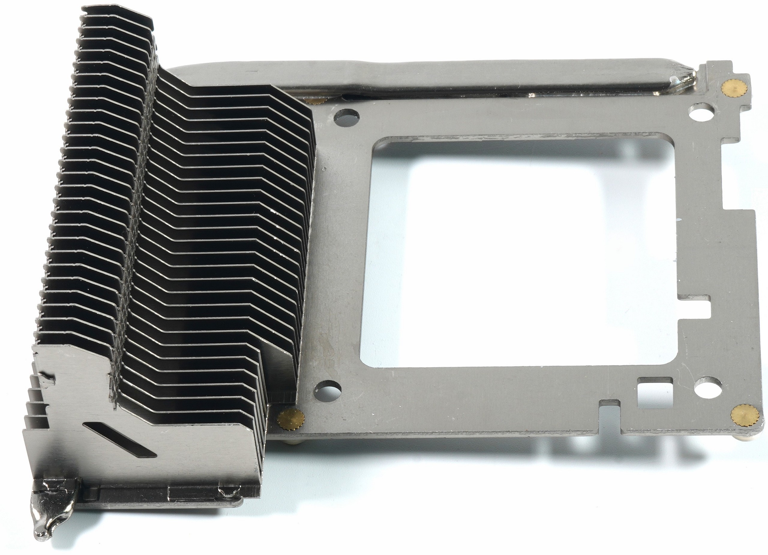
The picture below shows the separate RAM cooler with heatpipe, which is firmly screwed to the board. This takes the mechanical stresses off the RAM and also stabilizes the board. This does not make disassembling the card any easier, because one of the backplate screws sits directly underneath it. If you want to remove the backplate, you not only have to detach the PCB from the slot panel, but also all screws from the upper side of the board. Tricky, but you get used to everything by now.
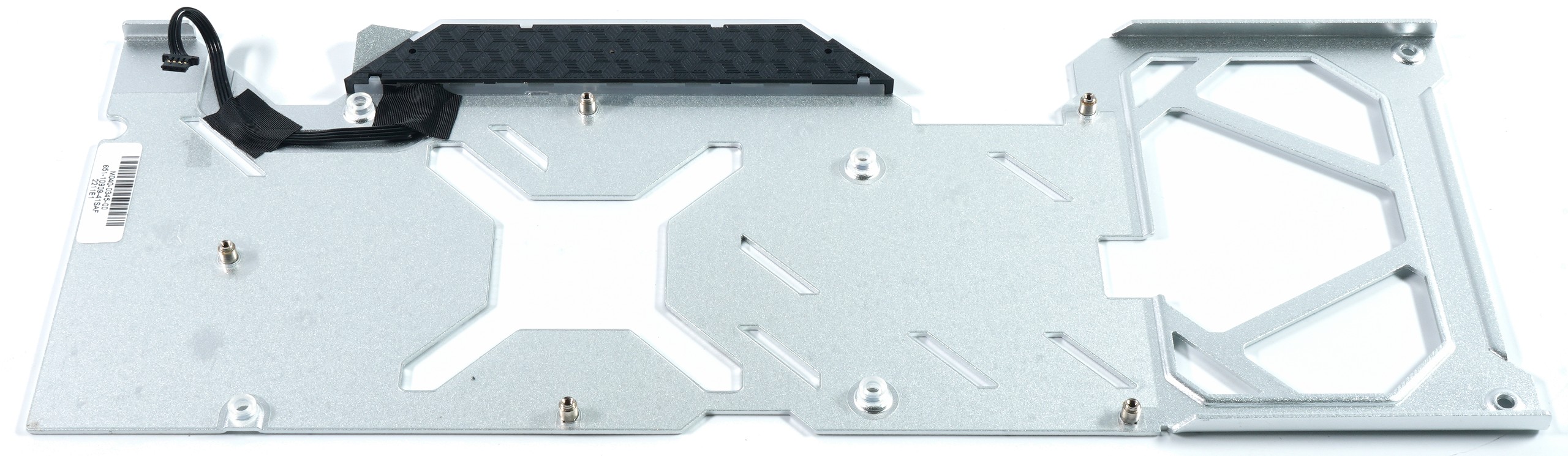
The backplate made of light metal is another part of the stabilization and also an optical eye-catcher with the translucent light field of the logo. The use of thermal pads is not provided for and one trusts in the qualities of the actual cooler. However, one could be divided here and insert pads afterwards. It certainly won’t do any harm.

- 1 - Introduction, Unboxing, Technical Details
- 2 - Teardown: PCB, Voltage Converters and Cooler
- 3 - Gaming Performance
- 4 - Gaming Power Consumption and Efficiency
- 5 - Power Consumption, Load Peaks and PSU Recommendation
- 6 - Temperatures and Clock Rates
- 7 - Fan Curves and Noise
- 8 - Summary and Conclusion


35 Antworten
Kommentar
Lade neue Kommentare
Veteran
Veteran
Mitglied
1
Veteran
Veteran
Urgestein
Urgestein
Urgestein
Veteran
Mitglied
Veteran
Mitglied
Mitglied
1
Veteran
Veteran
Alle Kommentare lesen unter igor´sLAB Community →