


The structure
For this little article, it’s pretty easy to get this system working, so let’s take a look at the simplified schematic:

At the bottom left we see the socket into which the 5V power supply is plugged by means of a 5.5 cm hollow plug. In the middle of the socket +5V is led, the sheath accommodates the negative pole. On the right side we see the used microcontroller, the ESP 8266. This wire is connected to the positive pole of the socket on [VIN] and this wire then goes in parallel to the [+5V] of the WS2812B LED strip. We proceed in the same way with the negative pole. This goes to [GND] on the microcontroller and in parallel to [GND] from the LED strip.
The pin [D4] of the ESP is connected to [DIN] of the LED strip and then it is done. Here again the pinning in the overview:
|
ESP8266 |
5.5 cm Hollow bush |
|
D4 on DIN |
Minus pole to GND Microcontroller and GND to LED strip Positive pole on VIN microcontroller and +5V on LED strip |
Once we have this setup we can turn on the power by plugging in the 5V power supply, now the LED on the microcontroller should light up. After that we disconnect the power supply again and connect the microcontroller with a micro USB cable to a USB port on our PC, please make sure that you really use a USB data cable and not a USB charging cable. The latter is missing the data lines D+ and D-.
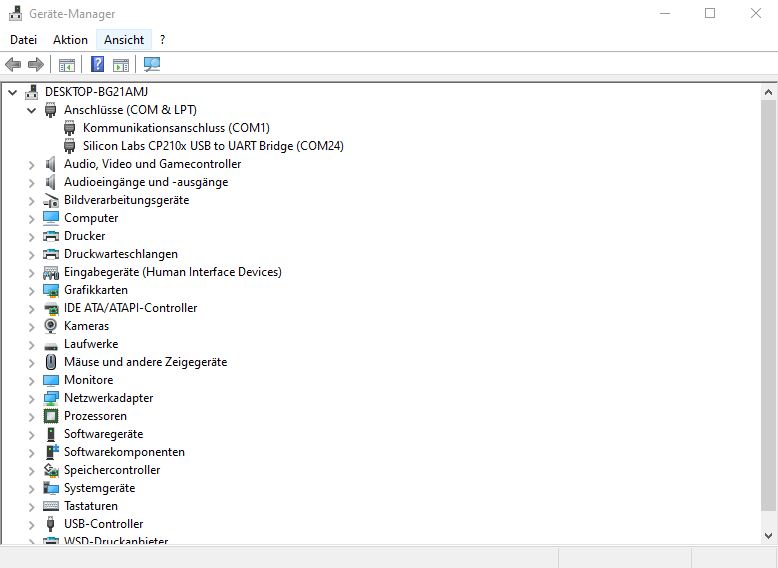
After the microcontroller is connected to the PC, you should find an entry in the Device Manager in the Control Panel under “Ports (COM & LPT)”, which is e.g. “Silicon Labs CP210x USB to UART Bridge (COM24)”. Attention: Depending on the board (Node MCU or generic) there may be other entries, the only important thing in this context is that a new device has appeared there.
The installation
The next step is to install the ESP Home Flasher on the computer (Windows) and download the appropriate firmware from the WLED site. Linux and other operating systems please check Github for their installation instructions.
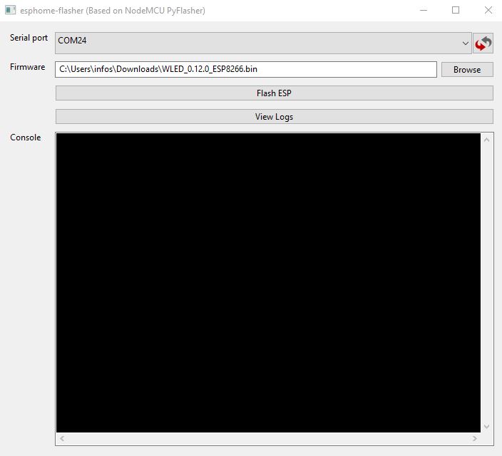
After the downloads we start the ESP Home Flasher and select the COM port where the ESP8266 is located. We bring the firmware, which we have also downloaded, into the software via the “Browse” button. Press the button “Flash ESP” and the firmware will be written. It is worth mentioning here that the flash process may take longer if another program was already running on the controller.
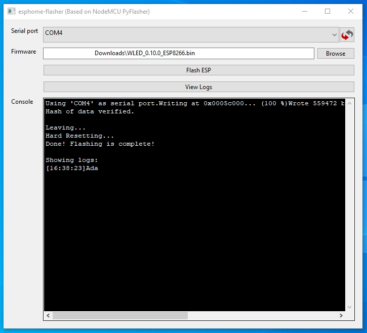
If you see this message, the flash process has been completed successfully.


5 Antworten
Kommentar
Lade neue Kommentare
Mitglied
Veteran
Mitglied
1
1
Alle Kommentare lesen unter igor´sLAB Community →