


What hasn’t there been in the last few weeks in terms of noise in all media. There was even talk of a VRM disaster or a TIM gate (thermal paste instead of solder), but if you take a closer look, the whole thing is nothing more than a long causal chain, in which an extremely hot-headed CPU marks the actual starting point. But what are we writing one, in principle there are even three of them. But one after the other, because we try to keep it as easy to understand as possible.
A short review at the beginning can’t hurt, so we’ll just briefly summarize the two core points, which are often discussed in the current discussions and according to which we’ve also structured our test:
(1) Skylake-X is already barely coolable out-of-the-box in normal operation, since the power consumption is already extremely high in individual situations and the thermal paste additionally prevents an optimal and appropriate heat dissipation.
(2) There is hardly any overclocking leeway left for the normal user and many motherboards are said to already limit the CPU inappropriately by themselves due to design flaws, such as insufficient cooling of the external voltage converters. Extreme overclockers can hardly do anything with the current hardware.
The whole thing is then usually spiced with far too much polemic, which, however, hardly does justice to the or perhaps even the actual problems of the potential buyers.
Test setup and measurement methods
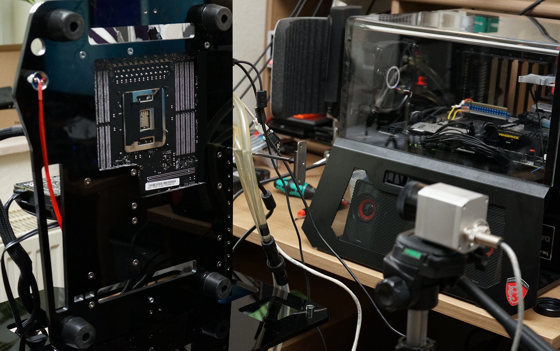
Therefore, we’ll grab one of the simpler motherboards for the Socket 2066, build a new benchtable for vertical operation and test what’s up (or maybe not). On the one hand, we’ll look at the sensor values of the respective areas, as well as their origin, and on the other hand, we’ll check the heating of the board in the area around the socket and voltage converter for plausibility through our non-contact measurements with the infrared thermal imaging camera.
In addition, we can even document the heating up and through, as well as show the process in special time-lapse videos. We are also interested in whether other components could be negatively affected by the resulting hotspots or the heat transfer in the motherboard.
For the safe reading of the sensors and the smoothest possible operation of the test setup, we naturally use the latest BIOS for our motherboard, as well as HWinfo in the currently latest beta version from v5.53-3190 (click on beta version when downloading!). After a closer inspection, a check with the manufacturer and also hints from the forum, we have corrected or deepened some details in the following.
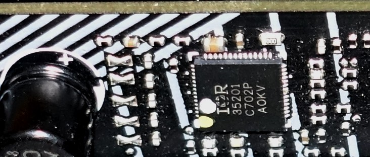
The board has a total of 5 1 phases for the CPU power supply, which are provided and controlled by an IR35201 from International Rectifier. This multi-phase buck controller supports Intel’s VR12 and quite obviously VR13 as well. If you suspect more voltage converter circuits for Vccin based on the coils, you’re absolutely right, because the so-called doubling allows two circuits per phase with five phases and thus also relieves the individual VRMs and equalizes the hotspots in terms of area. We will come back to this chip and its data like voltages and currents later.
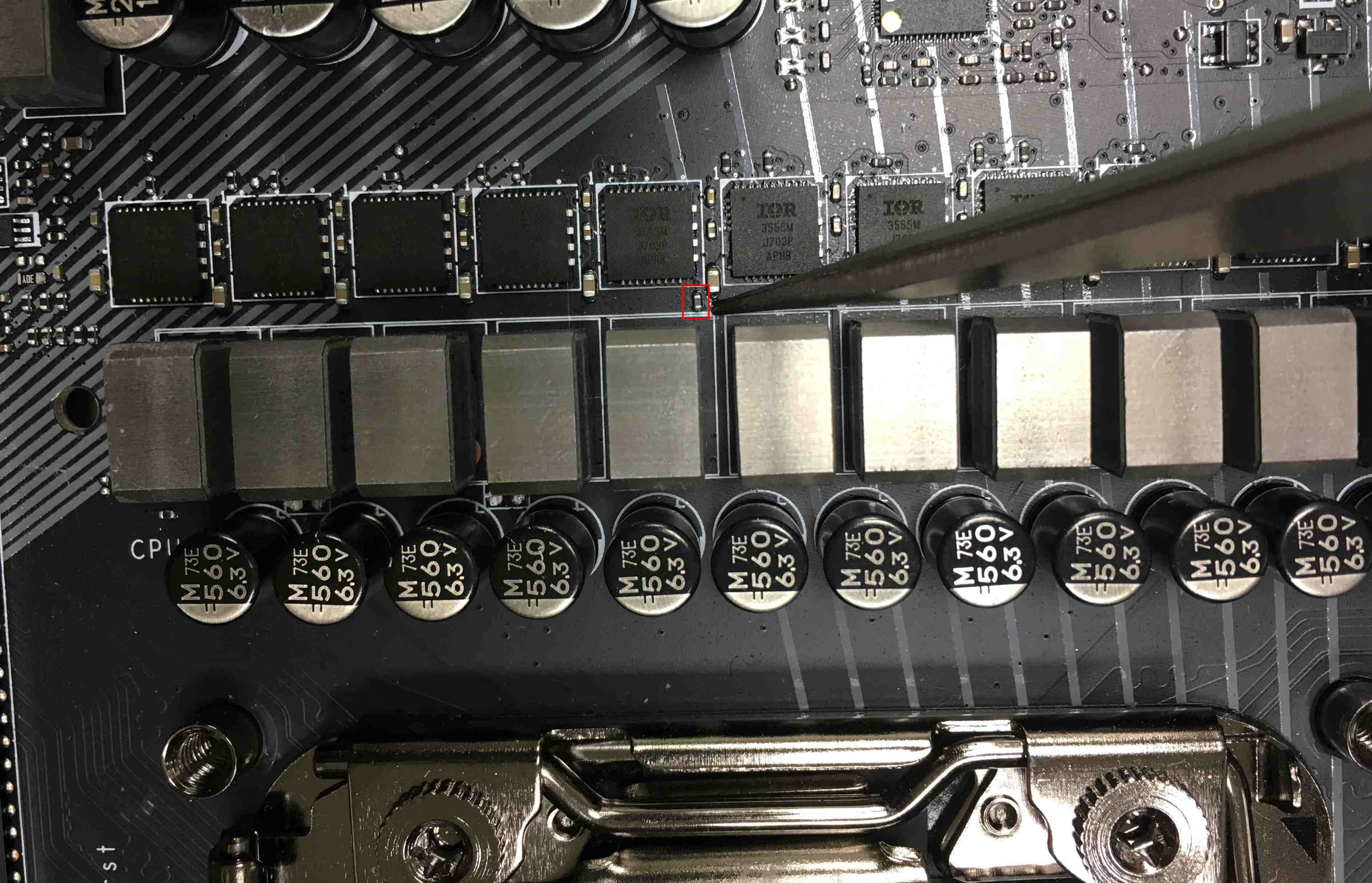
One IR3555 from International Rectifier is used as a voltage converter for each control circuit. These highly integrated power stage chips combine the necessary gate drivers, synchronous MOSFETs for the high and low side, and the Schottky diode in one package. In contrast to most of the usual MOSFETs, they also have integrated analog temperature sensors. But how else can you accurately determine the temperatures of these voltage converters if you can’t use a suitable IR camera?
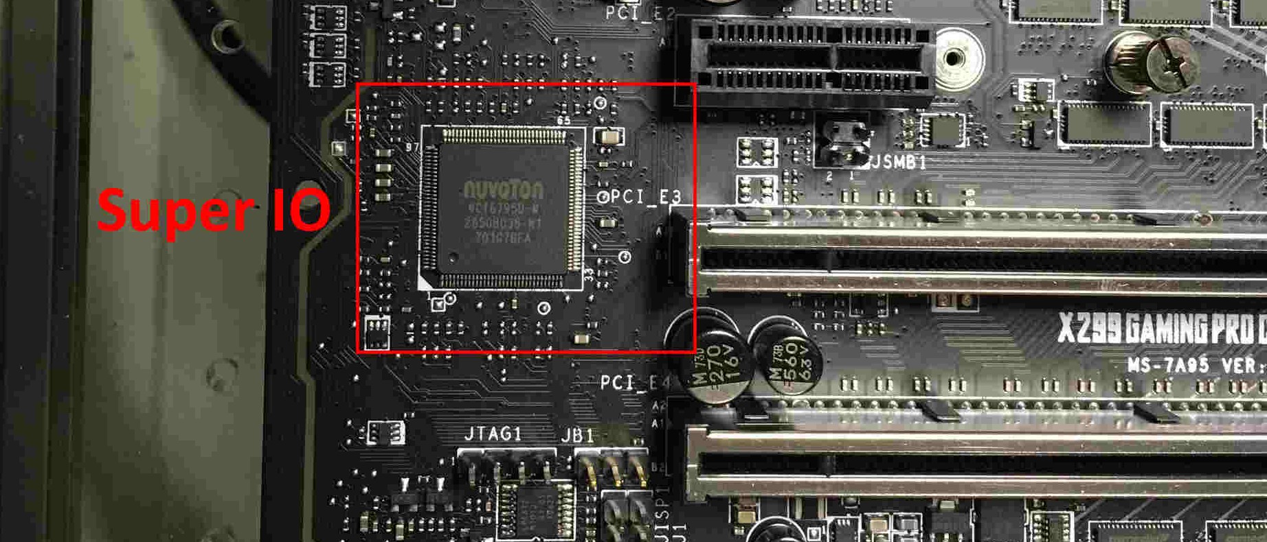
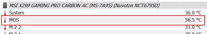
MSI uses the Nuvoton NC6795D as a so-called Super IO chip on the tested motherboard, which can record and provide a variety of sensor values. This also includes the temperature value of the voltage converters, which is determined by means of a thermistor placed centrally between the power stage chips (picture below). We have therefore chosen the measuring point for our video acquisition on the back exactly below this thermistor.
Furthermore, we also check the temperatures of the coils and capacitors of these voltage converter circuits, as well as the board temperatures up to the CPU in the further course.

Forced downclocking and emergency shutdown
In order to better understand the further tests, as well as the problems that occurred and were often discussed far too polemically in forums, we need to know that the motherboard manufacturers use some safety mechanisms. This includes, for example, that our test board clocks the Skylake-X down to 1.2 GHz at exactly 105°C measured temperature at the thermistor (HWinfo under line MOS, Nuvoton NCT6795D) and maintains this state until the temperature has dropped below 90°C. Only then does it return to full throttle.
This makes sense when you know that the flash point for the used PCB material (FR4) is significantly higher, but the recommendations for a maximum temperature in continuous operation are only between 95 and 105°C, because especially multilayer PCBs could otherwise be affected by dry-out (drying out), bending and possible hairline cracks of the conductor paths. This is to be welcomed, because graphics card manufacturers usually have the (unnecessarily) better nerves in this problem zone.
If you use Intel’s Extreme Tuning Utility (XTU), this downclocking is displayed as Thermal Throttling: Yes in yellow. But what about status indicators like Motherboard VR throttling? We also have to add a small supplement at this point, which concerns the values read out by HWInfo. What is far less known is that the IR35201 also returns temperature values. These values for VR T1 and VR T2 are significantly higher and at first glance also quite contradictory to those of the external sensor.
At first it was obvious that here, as so often, only a kind of chip temperature of the controller is output. This would be similar to what was supposedly displayed as voltage converter temperatures VRM1 and VRM2 on graphics cards with these PWM controllers in various tools (AMD cards usually used these controllers). The chip almost always measured itself there. However, with the combination of IR35201 and IR3555 that occurs here, it can be assumed that the voltage values output by the IR3555 and in relation to the temperature inside are also used
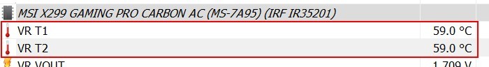
An upper limit of 125°C is set for these values, before the XTU yellow warns of motherboard VR throttling: yes and the CPU is also clocked down to 1.2 GHz. Above 135°C, the motherboard is even simply shut down without warning because the generated voltages could otherwise drift dangerously outside the specifications and damage the hardware.

But the CPU also protects itself. Based on various integrated digital temperature sensors (DTS), the temperatures of the computing cores and the package are determined. These are calculation values whose accuracy increases with rising temperatures. Everything below 40°C can actually be forgotten, but from about 80°C, i.e. the range where it really matters, it becomes quite accurate. However, we can also see that both the temperatures of the cores and the package can lead to a thermally induced throttling of the clock.
The package temperatures in particular also include the power loss of the IVR, i.e. the voltage converters integrated in the CPU for providing the individual partial voltages of a CPU. Here, especially with high overclocking and manual voltage boost, unexpected limit overruns can quickly occur, which not every tool can immediately detect with certainty. Then the CPU throttles without the user being able to see the cause. There will be more about the IVR in a moment. First, however, we will summarize once again:
Fact Sheet #1
A clock reduction of the CPU can be triggered by too high core or package temperatures inside the CPU (which is most known), as well as by the Super-IO chip because of too high VRM temperatures or the PWM controller because of too high, own chip temperature and the danger of an unstable voltage supply. However, the fact that the PWM controller can supply VRM temperatures is an urban legend.
The test system in detail
We have summarized all hardware components, measuring devices and tools in a table:
| Test system and measuring devices | |
|---|---|
| Hardware: |
Intel Core i9-7900X MSI X299 Gaming Pro Carbon AC 4x 4 GB G.Skill RipJaws IV DDR4-2600 Nvidia Quadro P6000 (workstation) 1x 1 TByte Toshiba OCZ RD400 (M.2, System SSD) |
| Cooling: |
Alphacool Ice Age 2000 Chiller Alphacool Ice Block XPX Alphacool Polar Bear 240 (AiO) Noctua NH-D15 (air) Thermal Grizzly Kryonaut (for cooler replacement) |
| Monitor: | Eizo EV3237-BK |
| Power consumption: |
Direct DC measurement via shunts (voltage drop) Direct DC voltage measurement at the measuring points Non-contact DC measurement at EPS supply connection 2x Rohde & Schwarz HMO 3054, 500 MHz multichannel oscilloscope with memory function |
| Thermography: |
Optris PI640, infrared camera PI Connect evaluation software with profiles Still images and radiometric videos |


1 Antwort
Kommentar
Lade neue Kommentare
Urgestein
Alle Kommentare lesen unter igor´sLAB Community →