


Load spikes that can cause even nominally adequate power supplies to suddenly shut down are all the rage right now, especially since the launch of NVIDIA’s current Ampere generation. It is also undisputed that this leads to the creation of legends and, of course, the accessories industry. But is there any point at all in placing a capacitor between the 12 volt cables and ground outside the graphics card, i.e. just after the 8-pin sockets? Yep, but leaning more towards no. Since the whole thing can be measured and explained, I just went for it.
Test design and methodology
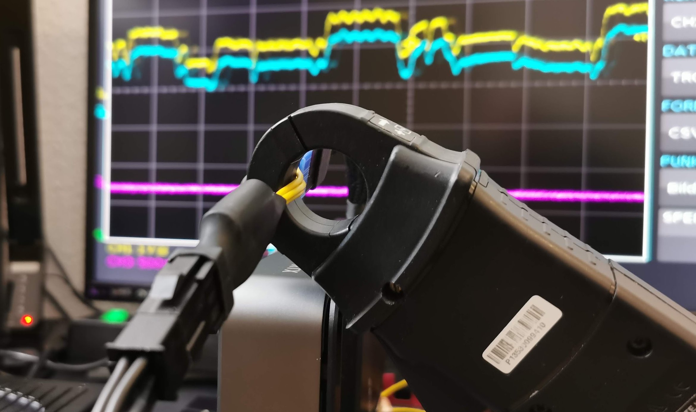
The test setup for this is relatively simple, because on the one hand I measure the flowing currents directly at the graphics card, so just behind the connector. In the following measurements we always see these values as a blue curve. In the picture we see one of my capacitor adapters and when measuring without adapter the clamp sets at the same position, but then directly on the PCIe connector cable.
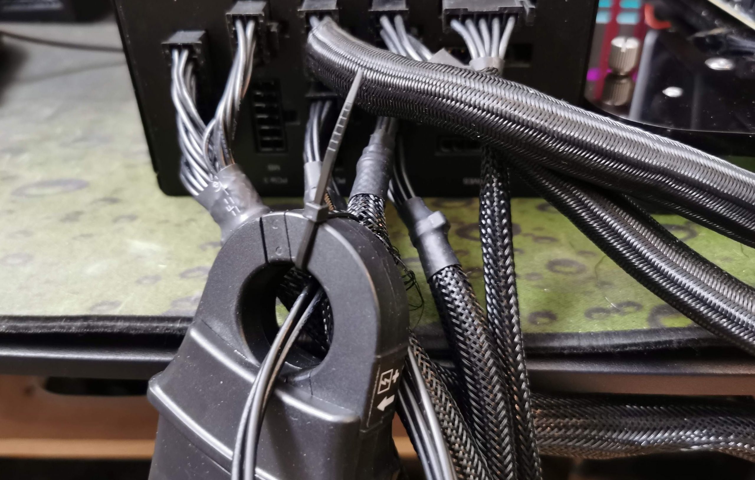
At the same time I measure the currents also directly at the power supply, i.e. just before the connection socket at the fully modular power supply. A be quiet! Straight Power with 1000 Watt nominal power and pleasantly low ripple. These values are later represented by the yellow curve. The red curve, which also appears in the curve diagrams, represents the difference between the flowing currents (blue minus yellow ), so it is a kind of loss curve.
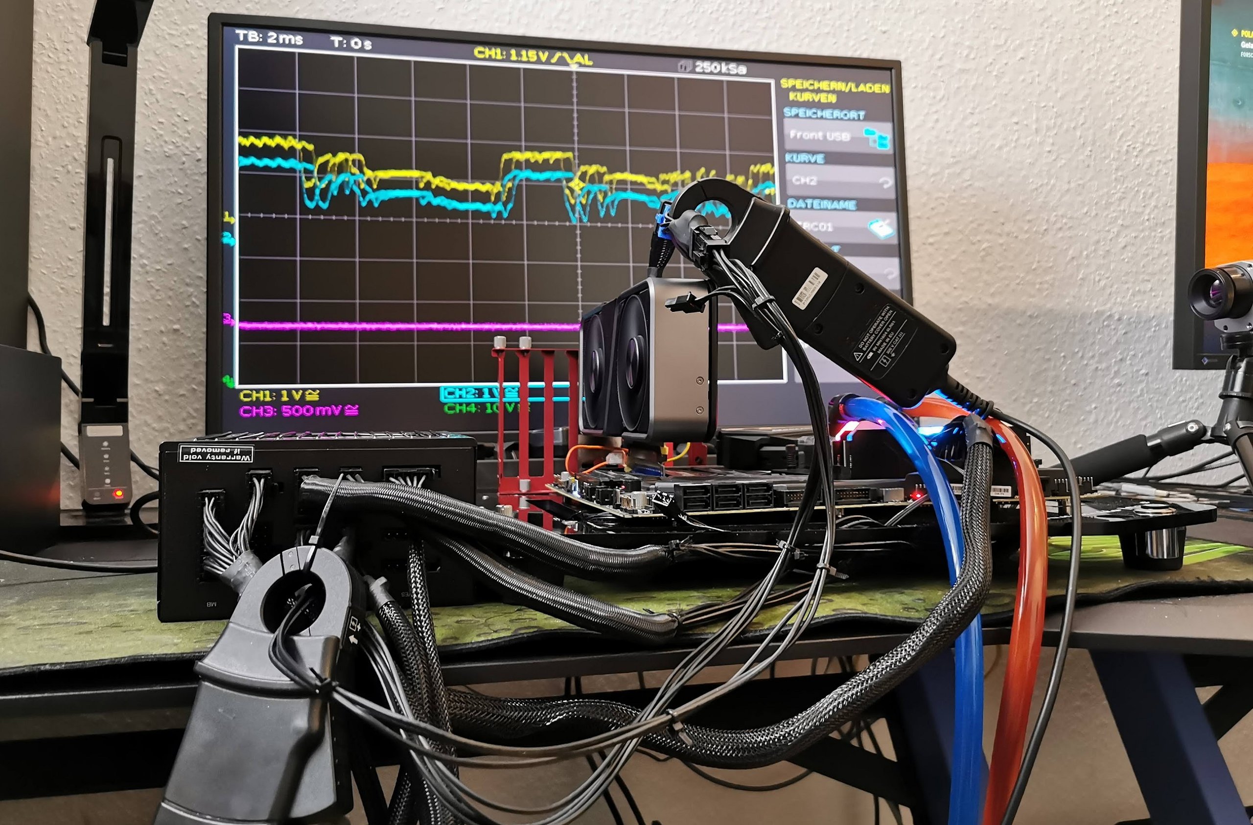
The following picture shows the test setup in one piece. The purple curve here is the operating voltage, which I measure directly at the graphics card to check. However, you can already see from the picture that there are no voltage fluctuations even in the microsecond range and the slight fringes represent the normal ripple that you always find. Exactly for this reason I have listed the respective power in watts as a product of current and voltage in the graphs, also for better comprehensibility, and not only the currents. This should be easier for the general public to understand.
For the test, I’m intentionally using a model with only a single 8-pin power connector in the form of the GeForce RTX 3070 Founders Edition, because it does make measuring in the above setup much easier. However, even with this card, not all phases of the GPU power supply (NVVDD) hang from the external PCIe connector. but a whopping 5.5 amps (i.e. the maximum allowed by the PCI SIG as a standard) also flow through the motherboard slot! Just under 66 watts of the total power consumption of 225 watts therefore doesn’t go through the connected PCIe cable, which is a little less than a third. Nevertheless, there is still a fair amount of current flowing through the cable.
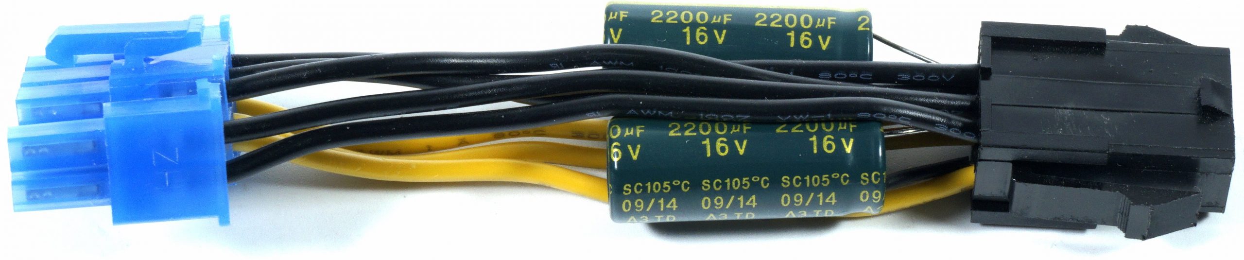
I experimented with different intervals, capacitances, and capacitor types: aluminum electrolytic vs. aluminum polymer capacitors and capacitances from 160 to 4400 μF, and measurement intervals from 100 ms to 6 ms (which then gives a resolution of 200 up to 10 μS for 6000 measurement points). However, with an average current flow of 12.7 amps at the power supply (and a power rating of just under 153 watts), all capacitances below 1000 μF were nearly ineffective, no matter what type of capacitor was used. From 1000 μF I only used electrolytic capacitors and in the end it was even a whopping 4400 μF via the intermediate station with 2200 μF, in order to still be able to visually represent significant differences at all!
By the way, the suggestion for this series of measurements and first experiences resulted from my visit to the development department of FSP in Taiwan, when it was exactly about the then emerging topic of the more and more load-peak-happy graphics cards. So we can see that the topic is not new, just much more important now than it was back then. At this point I deliberately refrain from explaining the differences in capacitor types in more detail, because these have proved to be rather unimportant for the current experiment. as well as other details that would irritate rather than enlighten the general public.
Input filtering on graphics cards, output filtering on the power supply and the connection cable
The so-called input filtering is actually more of an output filtering, which helps to suppress the high-frequency influences of the with 300 to 500 KHz quite fast switching voltage converters on the rest of the system. While NVIDIA still relies on one coil per rail/socket (low-pass) as a simple longitudinal choke in the base design kit of the reference, it is a real LC filter (see picture below) with coil (low-pass) and one or two capacitors (aluminum polymer, high-pass) in AMD’s case since Big Navi. So this is nothing else than a kind of second order low pass. So against the occurring maximum load peaks this all helps only conditionally, even if it may well mean some curve cosmetics. Well, a little.
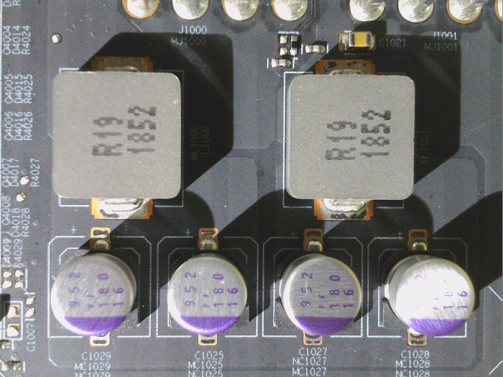
By the way, the direction of the LC filter can always be nicely recognized by the side of the coils on which the capacitors are arranged, if only one side was provided with it. On the picture above you can see that the direction of the filter goes from the direction of the VRM to the sockets (soldering eyes on top). And exactly now the question arises, what a capacitor positioned at the output side (thus still behind the socket) should actually bring. It is already a normal 1st order low-pass filter and would only be extended to a pi-filter in the end, which in our case doesn’t help at all.
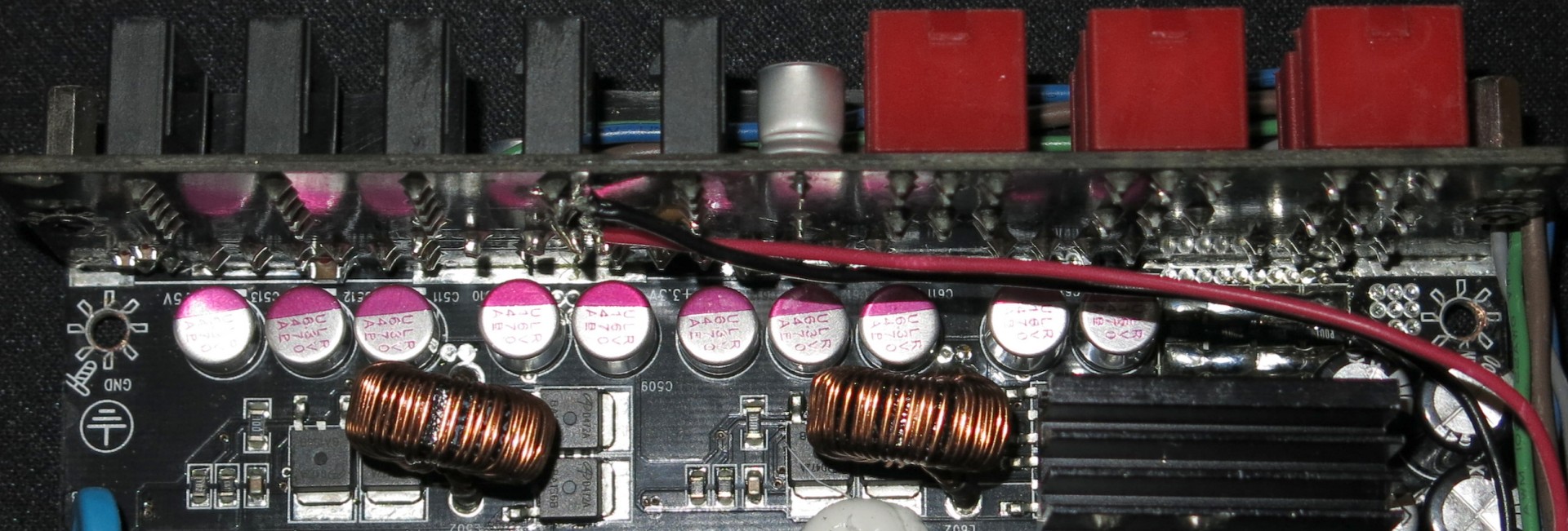
On the power supply side, every better power supply with modular cable management has one or the other solid on (or just in front of) the connector board anyway (picture below), but this is primarily to block the stray influences of the main transformer in the direction of the output to the graphics card. Because cables and circuit boards also act like antennas. So on the secondary side, everything is buffered and populated. That’s exactly where I measure the yellow curve.
There is also a neat PCIe connector cable between the two components. The lower the resistance (cross-section, copper quality, length), the less we will still be able to detect influences and line losses. Thus equipped, we can now go to work and measure the two extreme cases. Once completely without “filter” and once with a combination of two large electrolytic capacitors to be able to measure anything at all. As then…. please scroll on!


26 Antworten
Kommentar
Lade neue Kommentare
Urgestein
1
Urgestein
Urgestein
Veteran
Urgestein
Urgestein
Veteran
1
Neuling
1
Mitglied
1
Urgestein
Veteran
1
Urgestein
Mitglied
1
Alle Kommentare lesen unter igor´sLAB Community →