


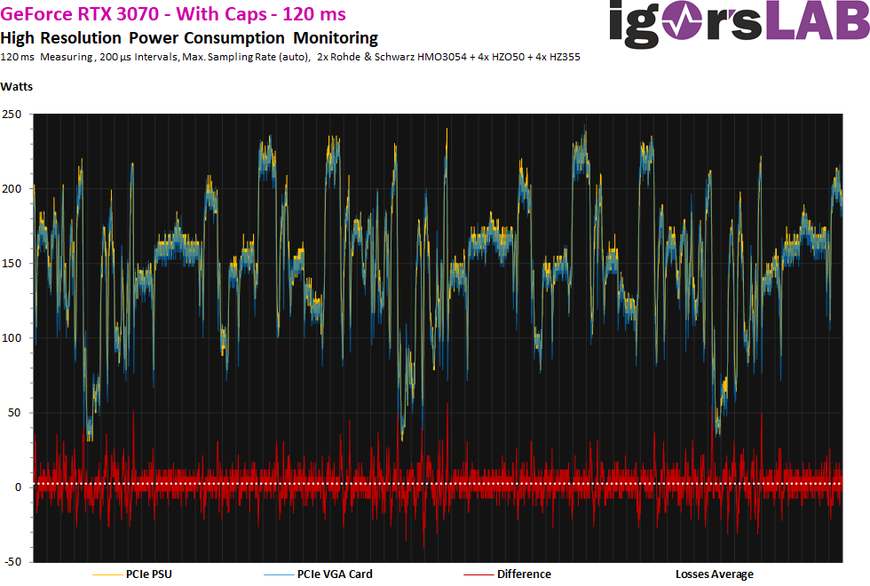
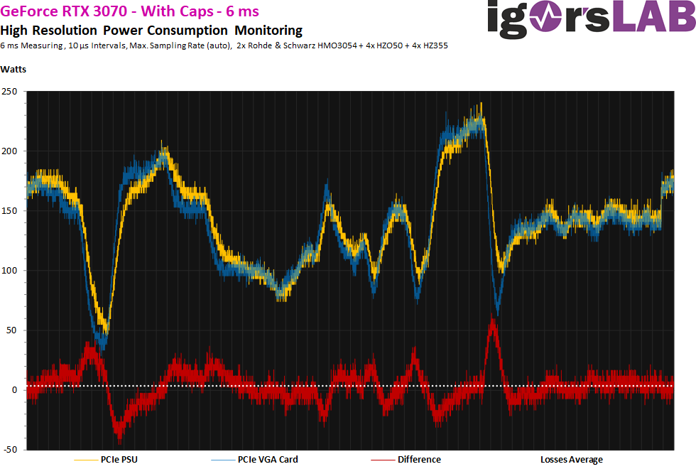
This is getting really interesting! We now use the adapter with the large capacitors and position the clamps at the respective line ends with a measurement duration of 120 ms as well. Here the curves on the timeline no longer lie neatly on top of each other and not only the deflection differs! This is the result of the capacitor (ripple currents) and the conduction loss due to the ohmic resistance of the cable. On average, I now measure almost 3 watts as the average value for the difference (red curve), almost double! The excursions with up to 50 watts include again also the residual ripple of the power supply, but it has really “cheated” something to it.
What is increasing here is the reactive power. Capacitors also only smooth out a voltage, but unfortunately not a current. For this, however, the current is always running ahead and if one is correct, the blue curve should then also shift to the left later in the offset to the yellow curve. So let’s be surprised. By the way, the load peaks here are again 245 to almost 258 watts with an average of about 154 watts at the socket. So nothing has improved there, because there are spikes as usual.
For a better understanding of the relevance, I would also like to note that we are generally moving in such short measurement intervals here, all of which do not yet have any influence on the protective circuits of the power supplies! So it is pure theory, which makes the sense of such a capacitor solution even more questionable. But I do not want to anticipate the conclusion, because there are very well differences in the measurements.
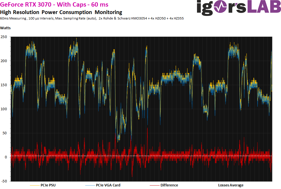
Even halving the measurement interval does not provide any new insights for the time being….
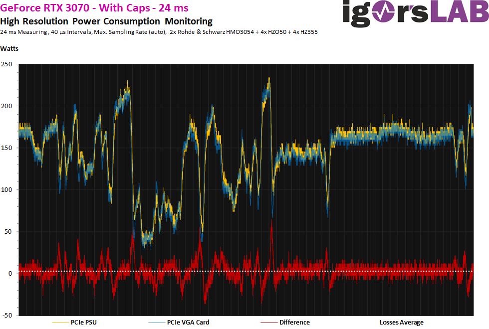
… only if one resolves even higher, one can already see a slight phase shift. But again, that’s not really enough to make a strong statement.
Now, at 12 ms, we can see more clearly and also the difference of both curves on the time axis. So the current at the card is a tad ahead of the current at the power supply!
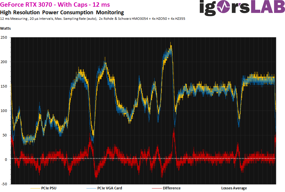
The last curve now shows very vividly that the capacitors are discharged exactly when the blue curve is above the yellow curve and are then charged again in the opposite case. The red curve represents the direction of the charge and discharge cycles very nicely. Higher values represent the charging cycle and vice versa discharging. Unfortunately, it also shows that the discharge does not start at the spikes, but much earlier, and thus one can hardly eliminate these spikes.
Faster capacitors would obviously improve the charging performance significantly, no question. But their capacities are then simply too small to be able to exert any significant influence at all. Dog-tail principle and you would need a whole battery of fast SP caps or MLCC to be able to move anything at all.


26 Antworten
Kommentar
Lade neue Kommentare
Urgestein
1
Urgestein
Urgestein
Veteran
Urgestein
Urgestein
Veteran
1
Neuling
1
Mitglied
1
Urgestein
Veteran
1
Urgestein
Mitglied
1
Alle Kommentare lesen unter igor´sLAB Community →