


Armor race and first attempts to walk with a single oscilloscope
If the VR controllers let the graphics cards switch so quickly, what really does it do except for the power connectors of the graphics cards? How hard is the power supply via the motherboard and where are the external PCI Express supply connections really required? I had designed the system for these measurements with a view to as small intervals as possible, which made the use of a very good (and unfortunately also very expensive) multi-channel memory oscillograph with memory function indispensable.
The basis was a 500 MHz multi-channel oscilloscope (HAMEG HMO 3054), which allows the joint storage of four channels and a meaningful remote control via Ethernet. In addition, there are several high-resolution AC/DC current pliers adapters (HZO 50), which can still be used without any problems for these high frequency ranges and which can be used mainly without area switching (full-range).
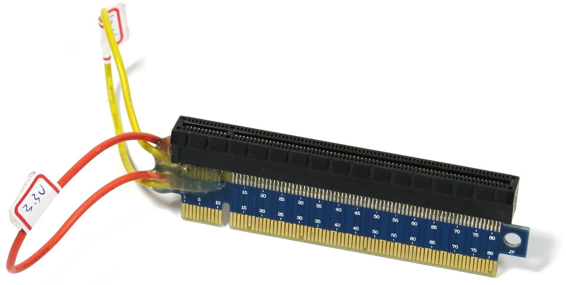
Another important tool is a special riser card with loops, which must also have extremely short signal paths, so that even modern third-generation PCIe cards run with them without any problems. This adapter is then plugby between the motherboard and the graphics card. Anyone who now thinks that the two tension rails looped through to the graphics card slot can simply measure the 24-pin connection of the motherboard will be disappointed. Because the motherboard uses here from the same source. Without a suitable Riser-Card nothing went and so there were again craft lessons and a lot of tuition money included.
After solving this small tinkering task, the strategic partnership with industry (HAMEG, Rohde & Schwarz) is now coming into play, because without usable laboratory technology and years of experience, despite all the ambitions, one quickly runs into the void. The interim result, as we know it from the reviews of the last few months, was certainly a first, encouraging success. Only four channels are at first glance still pure luxury, but when you drown the whole thing, you are about to face the next problem and wonder.
If one measures the currents for the two motherboard lines (3.3 and 12 volts) and the external PCIe power connection, only one channel remains to measure at least one of the voltages. Since most of the load happens on the PCI Express connection, I measured the voltage of the 12-volt rail there, determined the values for 3.3 by means of a multimeter and later used it as a fixed value.
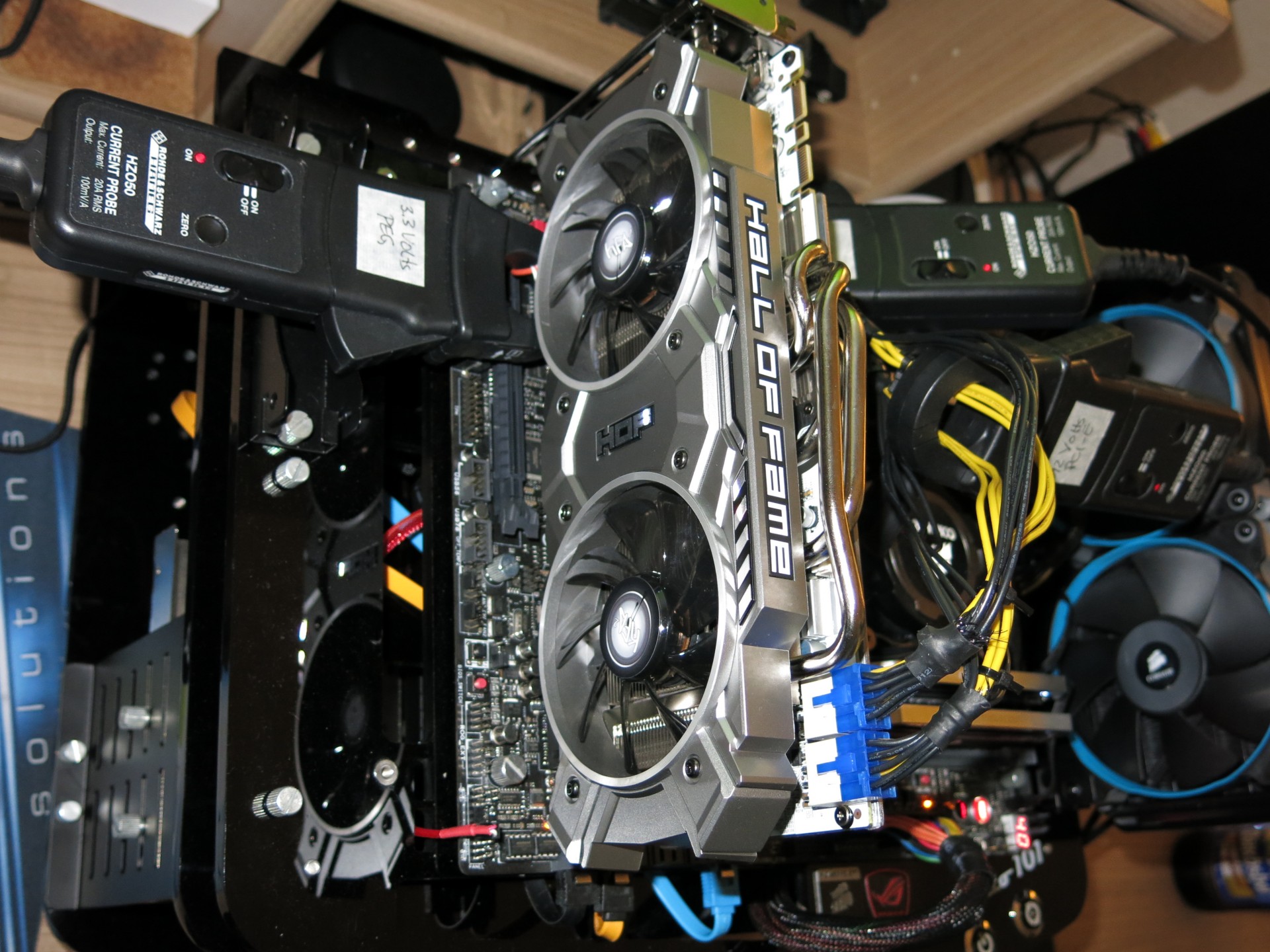
But at the latest with graphics cards such as the Radeon R9 295X2 and some board-partner self-designs, you notice that this is all just a lazy compromise: you can't easily combine the PCIe connectors into a single channel, if you want to different phases of the graphic card supply. Sometimes the currents flow in very short spikes into reverse richtug, which I would not have suspected.
The measurement with a single four-channel memory oscilloscope, three suitable current pliers adapters and a probe is at least around worlds better than things like socket measurement, pliers or current pliers adapters and multimeters, but unfortunately still inaccurate. And now?
4-point measurement and a double lottery
Did I write up arms race? The whole thing – if you really want to do it seriously – is already a little bad. If you really want to measure all four maximum supply rails per graphics card, you would need eight analog channels on the oscilloscope. You have to be able to measure both voltage and current in real time in parallel for each of the four individual rails and also save it! If you work with predetermined fixed values for the tensions, you can not only lie wrong again, but also do it, as we will see in a moment.
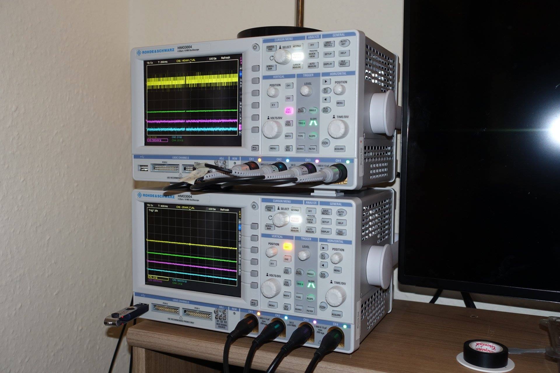
This is exactly where I had to start and, together with our measurement technology partner, i was looking for a workable solution. This in turn consists in measuring and recording with two such oscilloscopes in parallel (master-slave). This works quite perfectly in the middle of the day, so that I am able to use almost any breathing or coughing fit of the graphics cards (and other measuring objects such as motherboards) are plausible and resilient.
In the end result, I can now measure currents and voltages simultaneously in resolutions of up to one microsecond, depending on the task at hand. These intervals should, of course, be better adapted to the specific task, so as not to drown in the emerging flood of data. For example, if I resolve graphics cards in the 1-minute charts with one millisecond, the measured values in between in the microsecond range are already summarized as a useful mean in the oscilloscope.
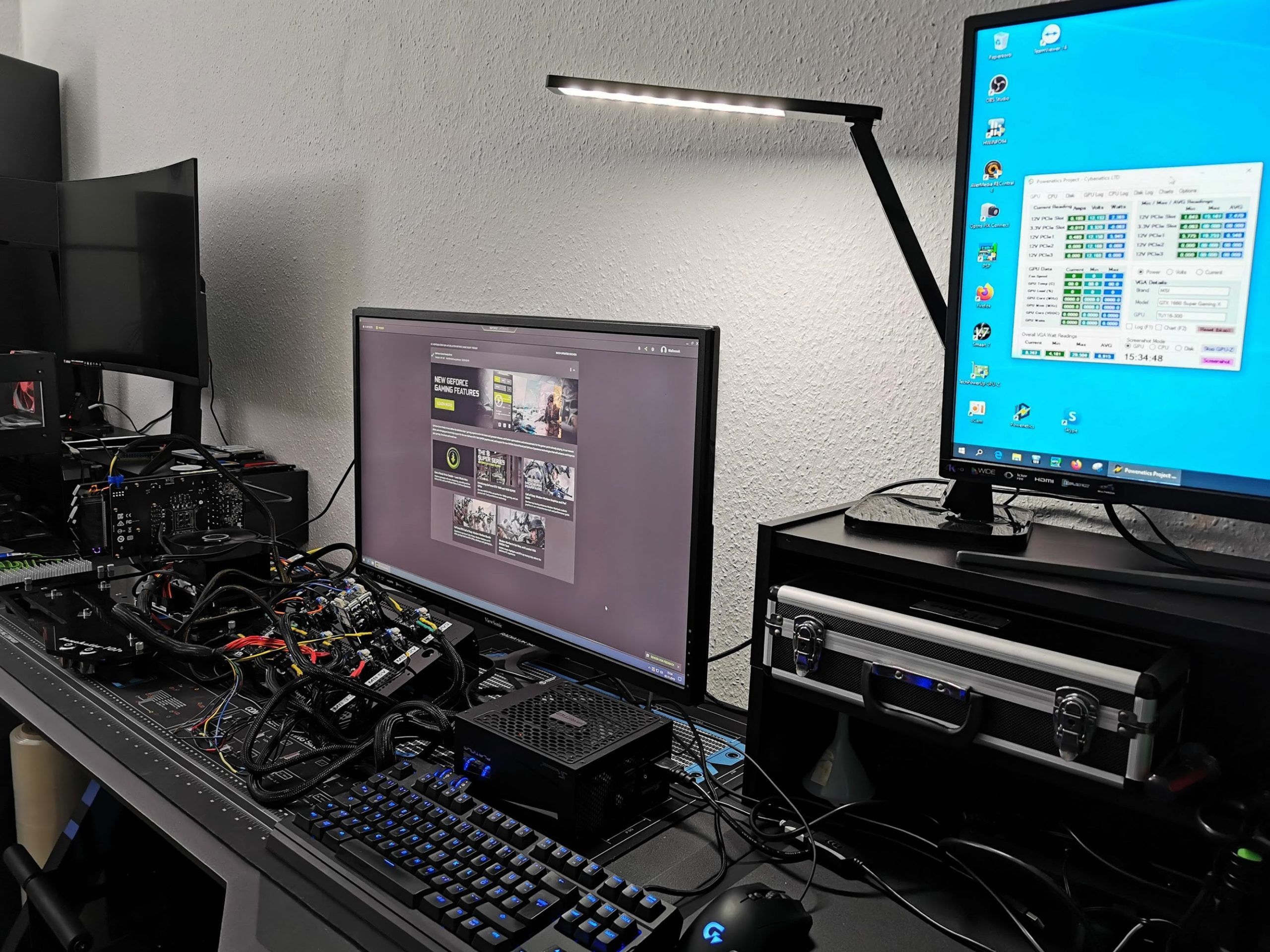
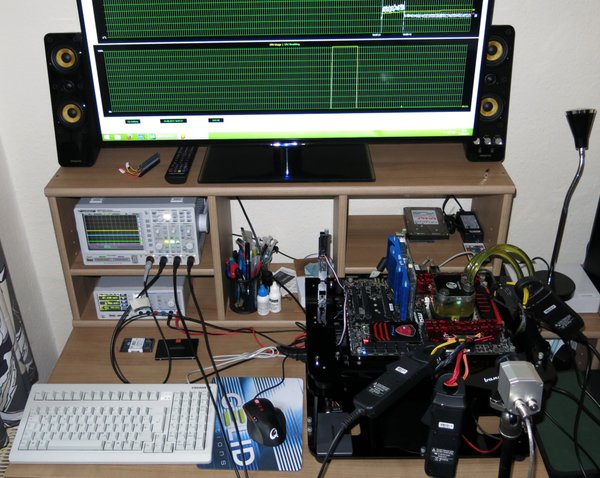
The current system for power acceptance measurement and graphics card analysis I had already shown on page 1 as a further picture with the oscillographs, here is again the description of the components in table form.
| Power Consumption: |
Scope measuring: MCU-based measuring |
|---|---|
| Thermal Imager: |
1x Optris PI640 + 2x Xi400 Thermal Imagers Pix Connect Software Type K Class 1 thermal sensors (up to 4 channels) |
| Acoustics: |
NTI Audio M2211 (with calibration file) Steinberg UR12 (with phantom power for the microphones) Creative X7, Smaart v.7 Own anechoic chamber, 3.5 x 1.8 x 2.2 m (LxTxH) Axial measurements, perpendicular to the center of the sound source(s), measuring distance 50 cm Noise emission in dBA (slow) as RTA measurement Frequency spectrum as graphic |
We can now see on the next page how all this looks in detail and what can be derived from such values. Keep friends, because now it's getting really exciting for the first time!
- 1 - Einführung und Projektvorhaben
- 2 - Grafikkarten und die Tricks mit der Leistungsaufnahme
- 3 - Leistungsaufnahme-Messung: Benötigte Technik
- 4 - Leistungsaufnahme-Messung: Praktische Umsetzung
- 5 - Radeon R9 295X als Netzteil-Killer? Myth busted!
- 6 - AWG was? Kabelsalat und Gegrilltes vom Chefkoch
- 7 - Schalten und Walten - Wir schauen ins Netzteil
- 8 - Bad caps, good caps? Die Mär vom japanischen Drachen.
- 9 - Zusammenfassung und Fazit


Kommentieren