Today it’s about non-existing coolers for unavailable RAM, so once again pure unicorn cinema for all who are only missing the RAM for the new Intel system with DDR5 modules. The fact that the parts want to be well cooled, and even have to be, is beyond question, especially when overclocking. Because what is quite often installed ex works is not always optimal, but I’ll get to that in a moment. In times of shortage like these, you like to take what you can get anyway, even if the refrigeration is no good at first. You can quickly make manual corrections. Really?
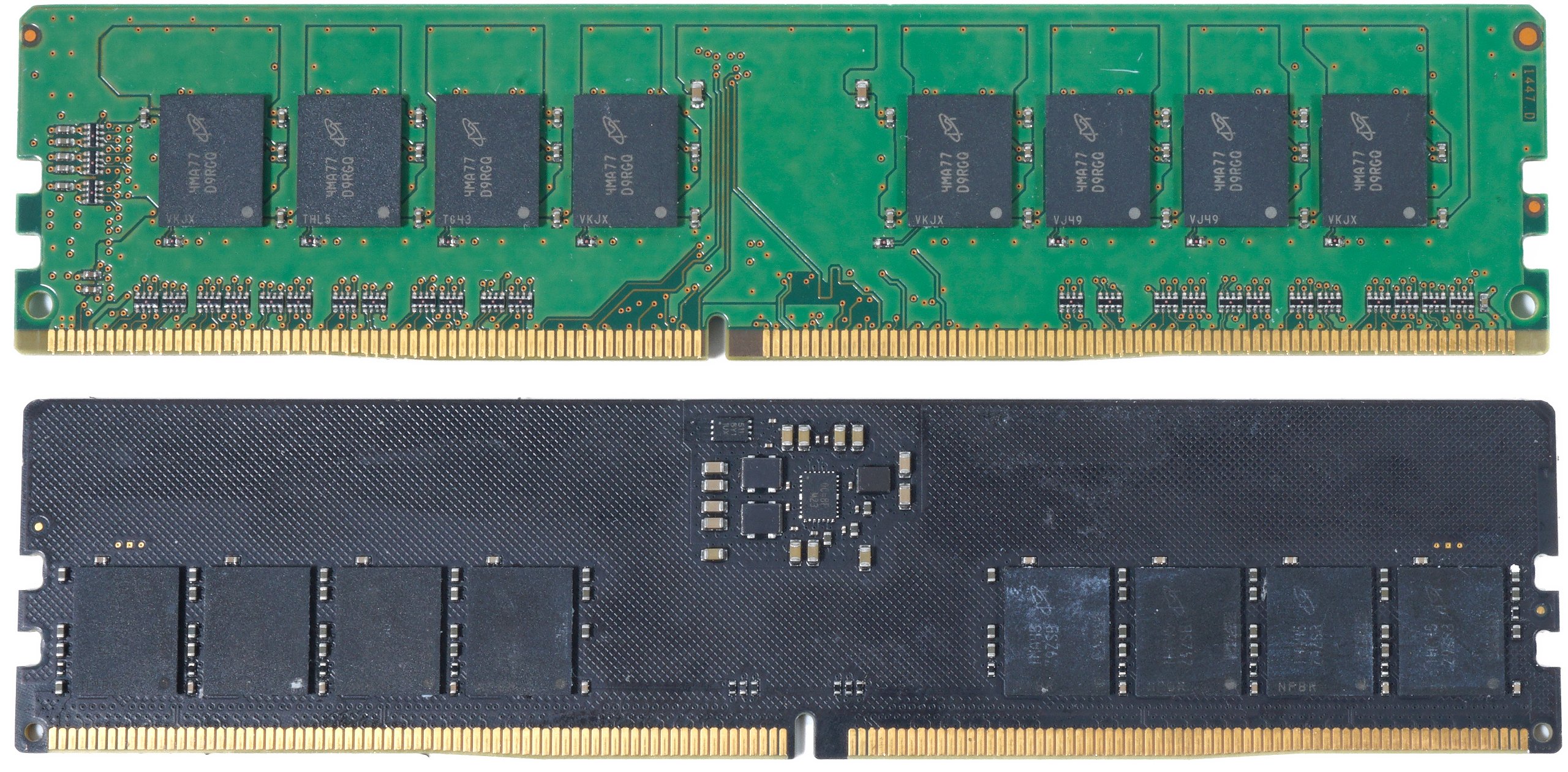
Let’s first compare two modules with the usual standard dimensions, which are very similar for DDR4 and DDR5. Height and length are at least identical, but you can already see here that the modules and the rest of the electronics are placed completely different. In the picture below you can see a normal, single-sided 8 GB DDR5 memory module, where a total of eight individual RAM modules with 1 GB each are used and are located in the bottom row.
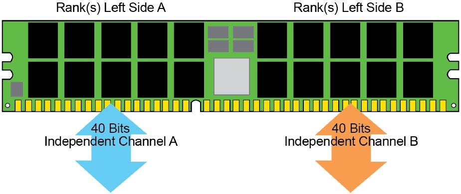
The maximum configuration of the front side with up to 20 modules (theory) is shown in the next picture. 16 modules are of course more realistic in the consumer area, but there is also the good server RAM with register module and ECC. We see that the top row of modules is almost flush with the edge of the PCB. Here we are already in the range of a millimeter and you have to consider that the modules do not have an underfill, but only lie hollow on the solder beads.
Thicker coolers, which already exert too much pressure on the top edge, could quickly cause the modules to tear off. Not really a nice outlook and a mental exercise for the manufacturers of third-party or water coolers.
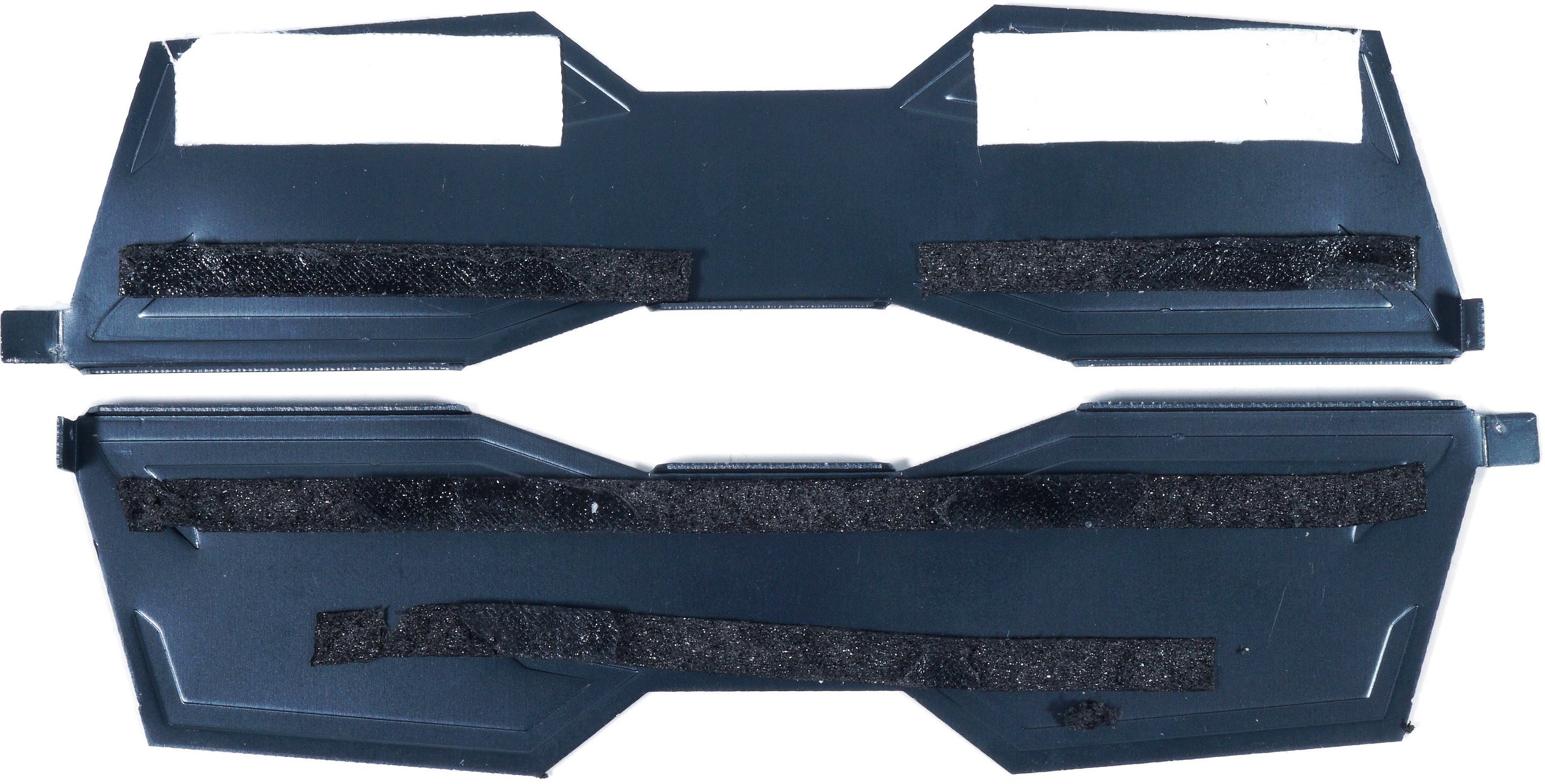
But let’s get back to what I found with my Extreme memory from OCPC. Here, it’s a rather thin aluminum heatsink, which was also fixed with pretty nasty adhesive strips almost undetachable. The only thing that helped was 4 plastic spatulas to clamp it and the good old hot air gun from the modding box. After more than 30 minutes of careful demolition, I was able to expose and remove the PCB with reasonably little residue. You can also see that here only the eight modules are thermally connected to the heatspreader with 2 strips of thermal pad each. The beading of the heaspreader is also not optimal, because there is less pressure on the modules and the pads at this point.
Well, what now? How do you get a cooler to fit, because the current parts don’t fit. What happens if you try it anyway with a lot of courage, what a 3D scan tells you about the height of all the components and what else there is to consider, you can read after the turn of the page!