


I don't want to build the whole thing too theoretically, but I decided to start this first setup seamlessly due to the positive response to the last article "Aqua Computer Flow Meter "High-Flow" in the laboratory test – What can a flow meter for 40 euros?" refine something and make it usable for normal laboratory life with the tests of water cooling components. But I will keep the dust-dry theory as short and general as possible and instead focus on practical examples, which everyone finds in their own water cooling.
What interests me most, however, are the pressure losses caused by the large components such as CPU coolers or GPU water blocks, which almost add up as long as all these components have been serially, i.e. in series. Further pressure losses due to turbulence, bends, connections, angles, etc. I want to neglect at this point, because I use exactly the same hose lengths and quick connectors for the bypass B and the connected component. Compressions, so that with a GPU block you really only get the difference between the cooling block and terminal.
Test system and test conditions
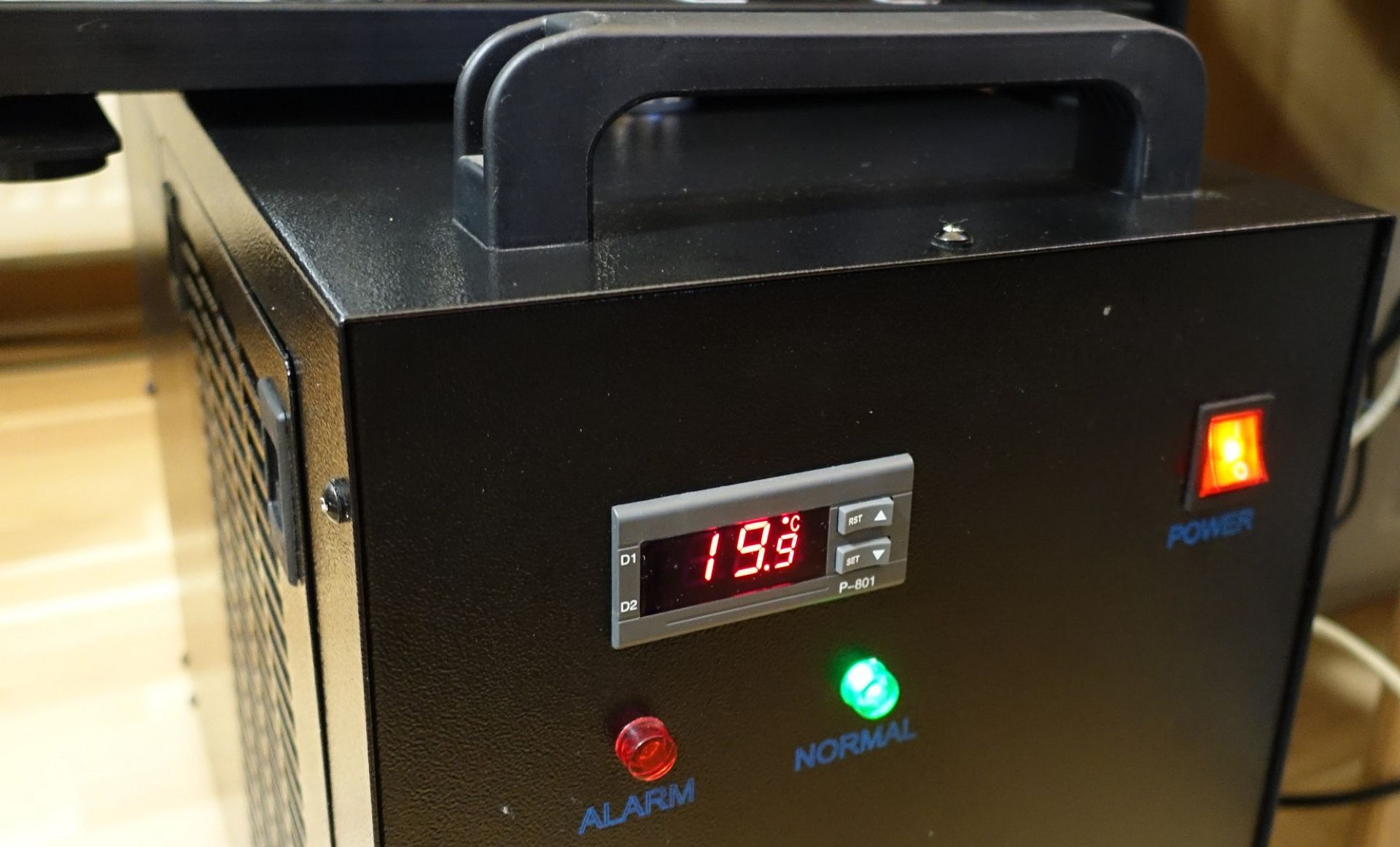
At the heart of the measurement setup are a potent pump that can deliver up to 200 l/h, a large compensating tank in the compressor cooler and an external one with a combined volume of almost 10 liters (here I reduced the amount of water a bit), as well as the compressor cooler itself, whose hysteresis has been adjusted so that the temperature can be kept in advance up to 1000 watts of waste heat supplied between 19.5 and 20.5 °C. Smaller deviations are not feasible, however, the temperature can be measured in the lead-up and thus also a possible delta can be used to correct the collected measured values via a uniform time stamp. Clean distilled water is used, nothing more. Any suspended particles would only distort the measurement.
In order to avoid fluctuations in the volume flow ("flow rate") in the area of the pump, I let them run unregulated at maximum power and redirect the volume flow with the help of bypass A instead. There, a fairly well dosed ball valve is used, which already helps to lower the volume flow in the large circuit through the "short circuit" via the bypass A. As a result, the volume flows are divided between the large and small circuit, so that the pump itself does not get a significant back pressure, which in turn could then push down the speed.
In order to be able to make an initial reference measurement here, the bypass B is first activated via the 2-way switch. With the fairly precise pressure control valve in the return of the large circuit, which relies on a large reduction by a screw thread, I can now adjust its volume flow relatively precisely and above all constantly and without large fluctuations. Even with larger volume flows around 3 l/m (i.e. 180 l/h), the measured fluctuation is only a maximum of 0.01 l/m.
If you are wondering why I did not position the valve in the lead-up, you can give a relatively simple answer. For the volume flow as such, the position in the circuit is rather unimportant, however, turbolenzen are created at the valve, which one wants to avoid as much as possible before an eneflow. In addition, the accumulation of air bubbles in front of the components to be tested can be almost completely excluded. By the way, the whole structure is flat and apart from the components, the hose is largely symmetrical.

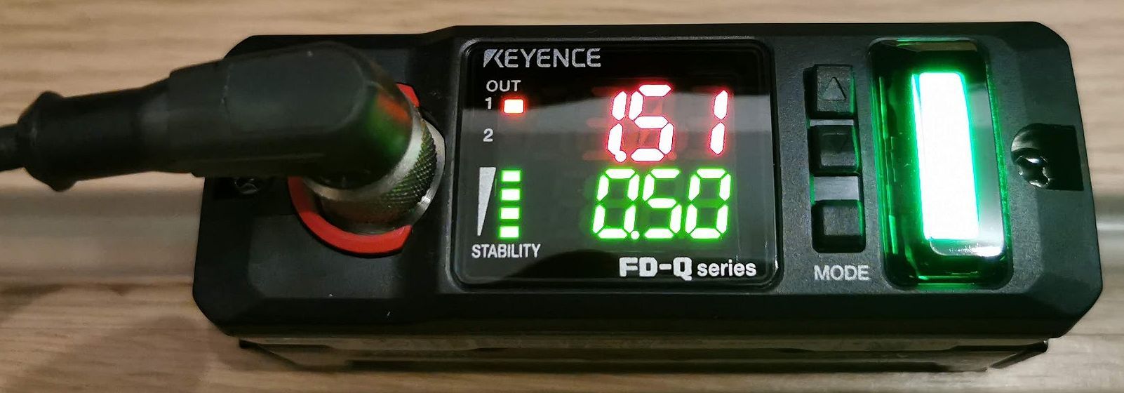
In order to determine the volume flow, I therefore rely on a well-defined measuring structure, which is not "picked apart" in the meantime. The centerpiece is a special, high-precision ultrasonic flow meter in the form of the Keyence FD-Q10C. This clampable flow meter works completely non-contact and does not affect the flow in the circuit. The accuracy far exceeds that of the mechanical solutions, so that here after calibration one gets a real reference value for the current volume flow.
The whole thing is fed via a special 4-pin M12 cable from an external power supply. In order to meet the pipe section used under the terminal exactly, I had the assembled components matched once again in a friendly laboratory in series connection to a calibrated device (M 1). The current volume flow is generally measured in litres per minute (l/m), not per hour. In addition to the limit value determination, the device also offers differential measurements and a freely definable zero point.
Equipped in this way, one can now evaluate one or more components in the measuring circuit and always has the possibility to switch between this circuit and the bypass B in real time for multiple value determination, in order to prevent a possible drift of the volume flow. and, if necessary, to re-regulate something. The measurement results on the second page show how the whole thing can then be applied in practice and what can be gained from it in terms of knowledge.
[table id=4 /]


Kommentieren