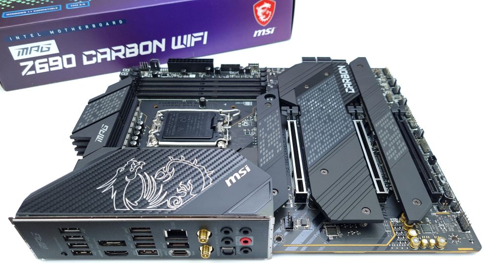
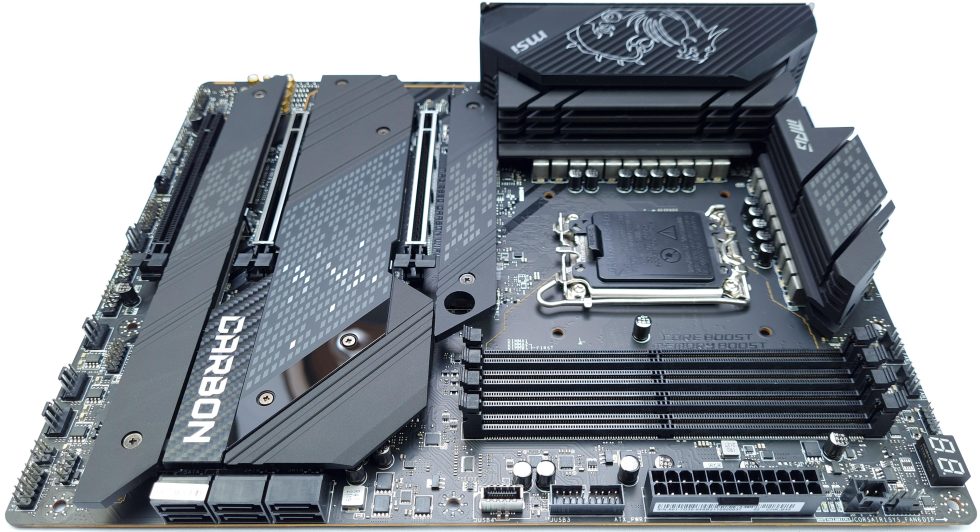
Are you still amazed about the so different power consumption values at the different launch reviews of Intel’s Alder Lake? In the meantime I have the data of a second motherboard model and I could hardly find any deviations to my measurements. The second board is an MSI MAG Z690 Carbon Wifi, which positions itself one price and performance tier lower. The starting point for today’s article, however, is the question of how such possible deviations can occur in the first place.
And this is where it gets interesting. After studying various reviews and changing several BIOS settings (which, by the way, also affect each other), I actually found that there can be several factors that can affect the VCCIA (i.e. what is displayed as Vcore in most tools). If I can write about a well-cooled CPU in my own tests and thus a slightly lower power consumption and others can’t, then in the end actually only the used substructure remains as the cause of the differences. And that’s why today we’re going to (have to) look at voltage regulation and generation, and also look at a couple of experiments that are highly interesting.
The voltage transformers: Switching Regulators
Now it becomes a bit theoretical, but unfortunately I can’t spare you that for a better understanding. But don’t worry, I’ll try to simplify this a bit. Since the primary concern is power efficiency and power supply capability, I will limit myself to this one type of regulator. The most common type of switching regulator in current IA designs is the so-called step down converter. To plan the power supply for an IA design, a motherboard manufacturer must first clarify the intended use and support modes.
In fact, if ACPI power states are to be supported, then some power rails must be on all the time. In addition, if a number of processor versions are to be supported for compatibility reasons, then the voltage regulator must support a wider than normal load range to cover everything.
The CPU core voltage has special requirements that go beyond the normal load range. In most cases, the core voltage of the Intel CPU relies on a so-called load line to specify the regulation and tolerance. This load line defines a slope of the voltage with respect to the current required by the controller. The slope is linear and is usually 2 milliohms. When the CPU is idle, the power requirement is low, but as the CPU load increases, the power requirement increases. However, the required current of the CPU is inherently very dynamic because it changes constantly between the two limits.
I will now describe on the following pages how the measured differences can come about and, above all, how affected users can help themselves. My own experiments with the so called AC/DC Loadline, the LLC (Load Line Calibration), the SVID Offset and the VF curve can surely help to understand the system better and to adjust the motherboard settings to the actual CPU quality. Because I don’t just want to explain, I want to maybe help.
These findings are not new and these mechanisms existed long before Alder Lake, but I am tired (I readily admit) of having to justify myself all the time. However, much of what I describe today has not yet reached the masses because many shy away from theory as a basis for practical optimization. But don’t worry, I’ve broken it down to the point where it doesn’t leave anyone out in the cold. I promise!


40 Antworten
Kommentar
Lade neue Kommentare
Urgestein
Urgestein
1
Mitglied
Neuling
Urgestein
Veteran
Urgestein
Neuling
Urgestein
Veteran
Urgestein
Veteran
Mitglied
Urgestein
Urgestein
Urgestein
Urgestein
Alle Kommentare lesen unter igor´sLAB Community →