


All the errors and confusions about the suddenly occurring value of the memory temperatures of AMD’s current graphics cards understandably lead to uncertainty among many users. Modern memory chips, such as Micron’s GDDR6 modules, allow you to read out the value of the chip temperature Tjunction, which is read out internally for special protection mechanisms (e.g. downclocking), which in itself is a nice addition. But the lack of knowledge about what it is really all about brings some contemporaries into distress and fear.
Definition of Tjunction, Tcase and Tboard
Interestingly Micron is completely silent about the GDDR6 in detail, because even the “Device Thermal Information” attached to the GDDR6 documentation ends with GDDR5. The manufacturer gives for his GDDR5 modules a maximum Tjunction of 100 °C, which seems quite plausible and agrees with the specifications for the maximum “operation temperature” of 95 °C. The maximum Tjunction of the GDDR5 modules is 100 °C, which is not only plausible, but also very high. But exactly at this point the ambiguities begin, what then where and why how warm becomes. Therefore we first have a look at the thermal scheme of a GDDR6 module.
The first interesting thing is PT, the maximum “power” Ptot, which is supplied as electrical energy and almost completely released again as heat (see red arrow). This should be around 2 watts per module, which doesn’t sound much at first, but due to the small structure width and heat density it is a house number. Because even if the memory module may look quite big as a package: the chip itself is rather tiny. You simply need a lot of space for all the connections and you also want to remain downward compatible:
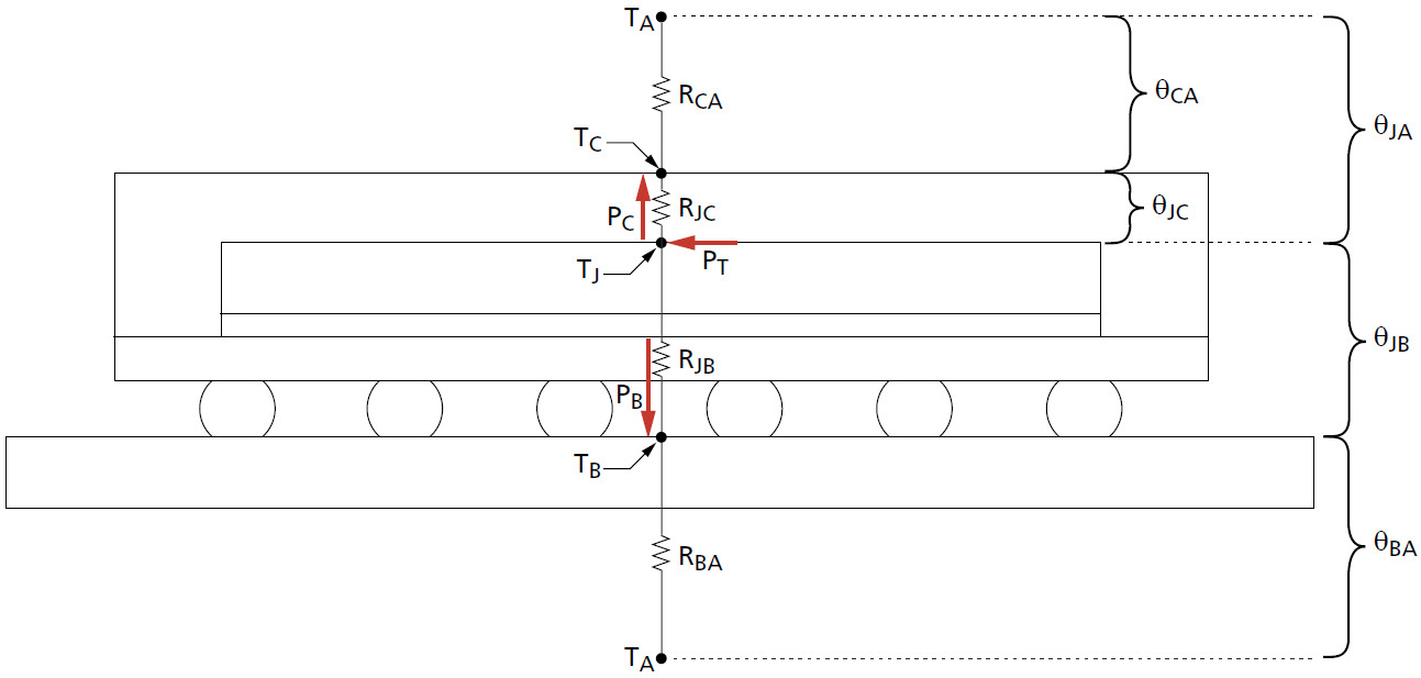
TJ (Tjunction) comes into play at the same place. Maximum chip temperature and maximum power dissipation are directly related. This is exactly the value that AMD outputs in the sensor loop as the storage temperature. I asked AMD myself and learned that it’s not an average value of all modules, but the absolute peak value, i.e. tjunction of the hottest module of a card. Also important are the values, marked with the other two red arrows, i.e. the power dissipation PB via the board and PC, which stands for the dissipated heat Pcase via the top of the case (package).
In addition, there are all thermal resistances of the individual layers and the combination of layers that belong together as a direction value upwards and downwards through the board, as well as the temperatures of the environment (air) TA or Tair at the top and bottom, whereby both can also deviate if a water block comes into play at the top. But more about that will follow later.
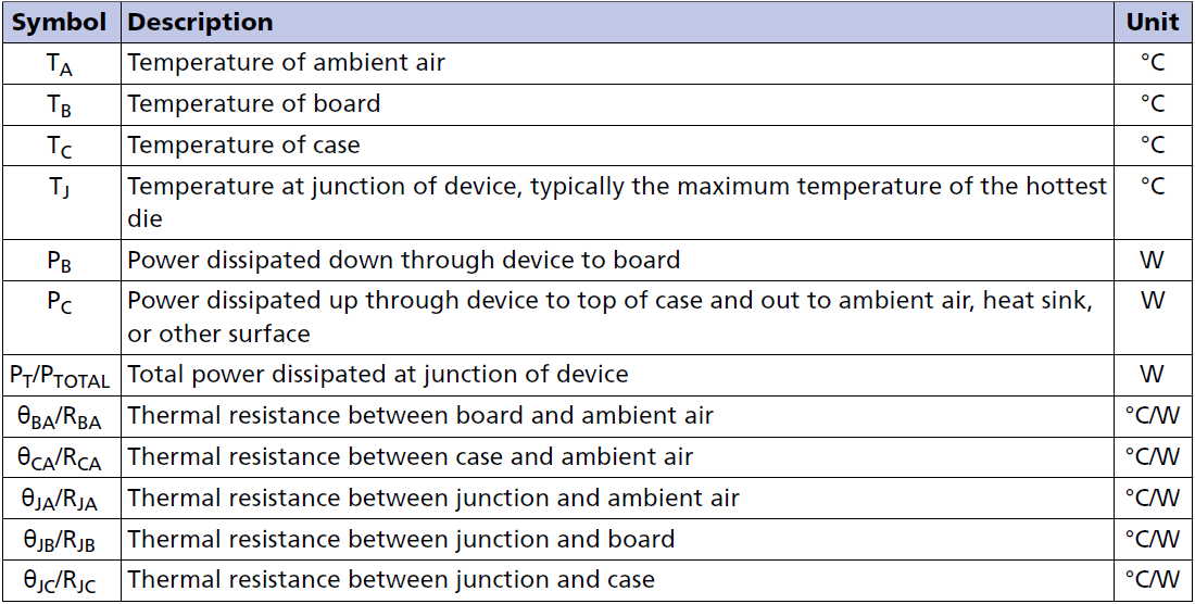
The challenge for a tester like me is on the one hand the very sparse (public) availability of the specifications and on the other hand the lack of the possibility to measure inside a module. Therefore I brought all three factors TJ, TB and TC together once in this basic article, because TB (Tboard) and TC (Tcase) I can measure, although in different ways. But I’ll explain that in a moment.
Test system for all temperatures
For use on the chip, i.e. for Tcase, I use the usual class 1 type K sensors, which are also used in industry, such as PC Partner, MSI or Gigabyte, if you want to measure graphics cards. Since I have a large pile of such sensors, I have measured the required number first of all for the highest possible accuracy and agreement among each other. I used the reference sensor, whose exact temperature behavior is known to me in the range of 20 to 100 degrees. I would see the measuring tolerance despite all care still with approx. 1 degree, which is however completely sufficient for our purposes.
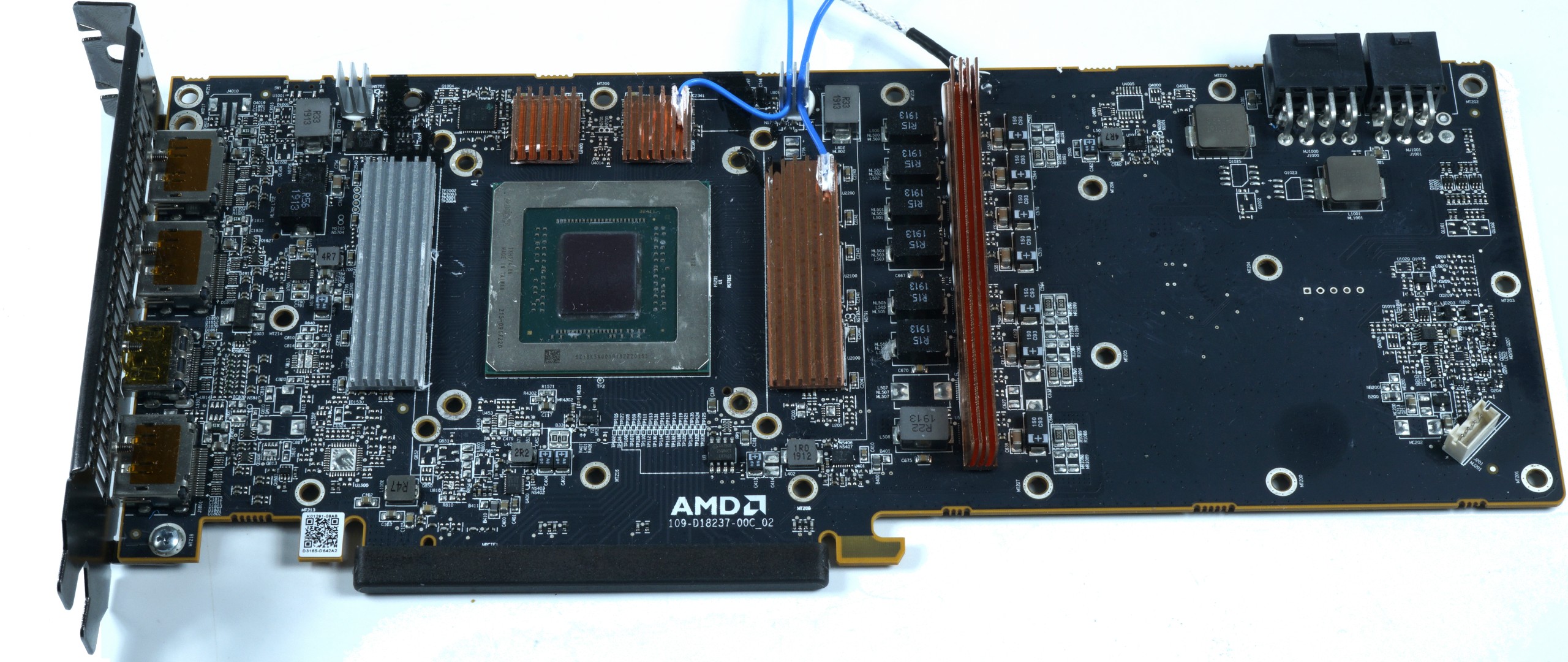
I embedded each of the two sensors for the memory in a copper heatsink and fixed them with thermal glue from above. The third sensor is in the voltage regulator copper block, which I regard as a pure supplementary value when it comes to PCB temperatures. This should not interest us as a control value, because it already leads too far at this point. I fixed the two copper coolers on the outside with thermal adhesive and good thermal conductivity, the inside surface is coated very thinly with thermal paste. The delta from the sensor to the surface of the package is about 1 to 2 degrees in our temperature range. Therefore I have added 2 degrees as offset to the measured values in order to be able to reproduce a result as realistic as possible.
I “tropicalized” the backside of the board with a special and transparent varnish, which is used in the industry to protect environmental factors such as high humidity and whose emissivity was measured at approx. 0.95 and is therefore known. If one were to apply a factor of 1 here, the measured temperature would be significantly lower. The ultra-thin special film attached to the benchtable has a transmission factor of approx. 0.97, which I also take into account in the measurement.
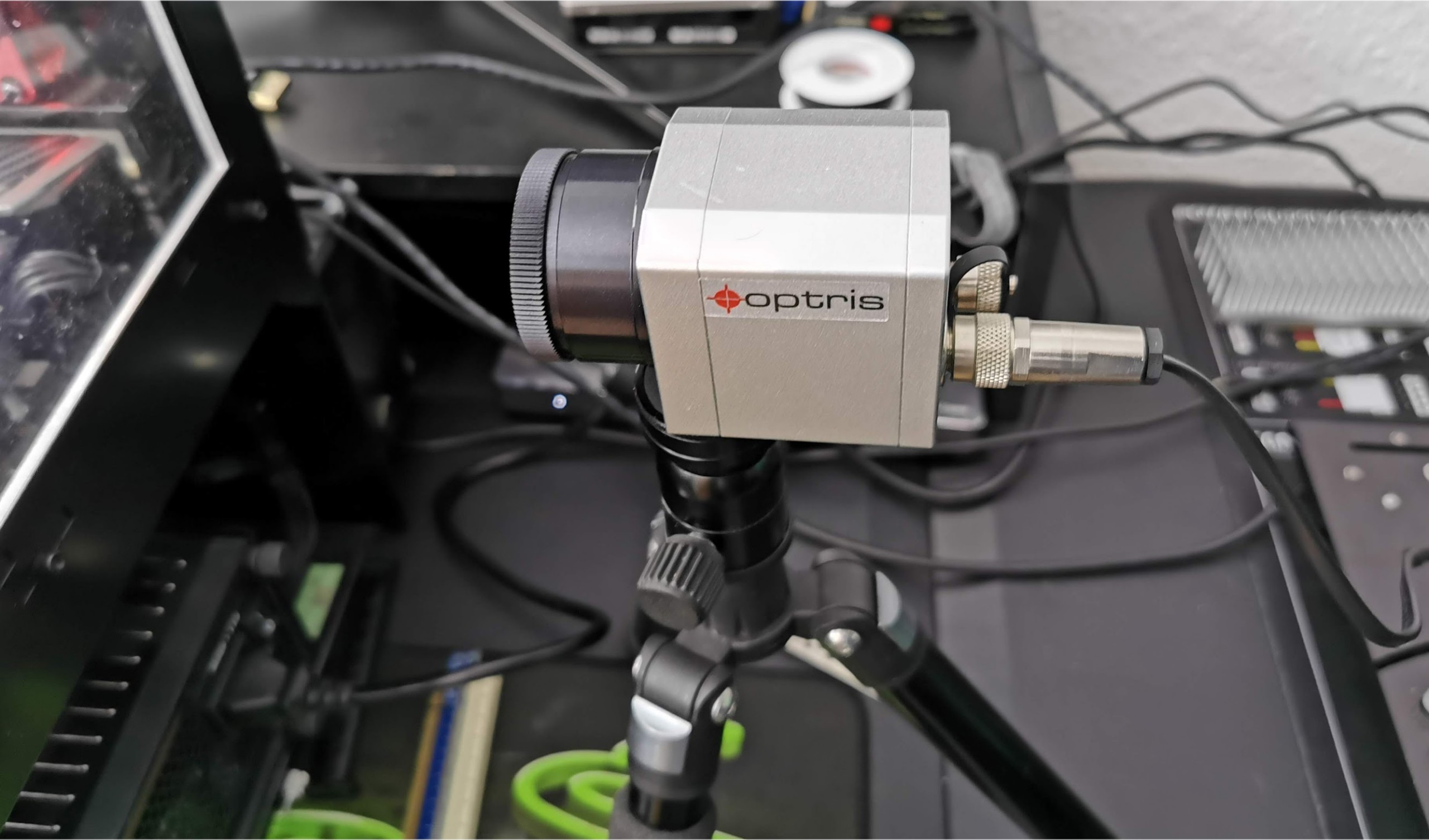
This makes it possible for me to perform a clever temperature analysis of the relevant surfaces with the Optris PI640, as the resolution of the built-in bolometer with 640 x 480 real measuring points is sufficiently high. Measurements are taken at the measuring points corresponding to the front. The 120-mm fans of the Morpheus rotate with approx. 1300 rpm each, which could be reduced significantly, but is in line with our measurement, as other disturbing factors can be safely excluded. And with the approx. 35 dB(A) this is not loud either.
Die Software GPU-Z liefert die passenden Werte im Sensor-Loop für das heißeste Modul-Innere TJ, also Tjunction. Das Delta zwischen den drei Temperaturwerten ändert sich im Temperaturverlauf bei steigender Tjunction recht deutlich und hängt beim Anstieg auch nicht unwesentlich von der verwendete Kühlmethode bzw. der Temperatur des Kühlmediums ab. Gemessen wird auf der Referenzplatine einer Radeon RX 5700 XT, wobei ich für die Luftkühlung auf einen neuen Raijintek Morpheus setze, dessen neue, hybride Heatsinks auf Kupfer bzw. Aluminium man auf dem Bild oben sehen kann. Nach längeren Messungen und eingehender Beratung mit dem Hersteller haben wir den Einsatz von Kupfer auf den beiden relevanten Stellen für sinnvoll erachtet, während der dritte Speicherblock auch locker mit Aluminium auskommt. Den Kunden wird es wohl später beim Endpreis freuen.
| Test System and Equipment |
|
|---|---|
| Hardware: |
Intel Core i9-9900 K MSI MEG Z390 Godlike 2x 8GB KFA2 HoF DDR4 4000 1x 1 TByte Patriot Viper (NVMe System SSD) 1x Seagate FastSSD Portable USB-C Seasonic Prime 1200 Watt Titanium PSU |
| Cooling: |
Alphacool Eisblock XPX 5x Be Quiet! Silent Wings 3 PWM (Closed Case Simulation) Thermal Grizzly Kryonaut |
| Case: |
Lian Li PC-T70 Modi: Open Benchtable, Closed Case |
| Monitor: | Eizo EV3237-BK |
| Power Consumption: |
Non-contact direct current measurement on PCIe slot (riser card) |
| Thermografie: |
1x Optris PI640 + 2x Xi400 Thermal Imagers Pix Connect Software Type K Class 1 thermal sensors (up to 4 channels) |
| Acoustics: |
NTI Audio M2211 (with calibration file) Steinberg UR12 (with phantom power for the microphones) Creative X7, Smaart v.7 Own anechoic chamber, 3.5 x 1.8 x 2.2 m (LxTxH) Axial measurements, perpendicular to the centre of the sound source(s), measuring distance 50 cm Noise emission in dBA (slow) as RTA measurement Frequency spectrum as graphic |
| OS: | Windows 10 Pro (1903, all Updates) |


Kommentieren