Many trust the manufacturer's specifications in terms of accuracy when it comes to flow measurements for their own custom loop, but without being able to verify it in any way. If there is any information on accuracy, upper and lower limits or the measuring methods. Since I can now take fairly reliable measurements with an ultrasonic measuring device, I got one of the better and more expensive sensors from the trade and measured it exactly.
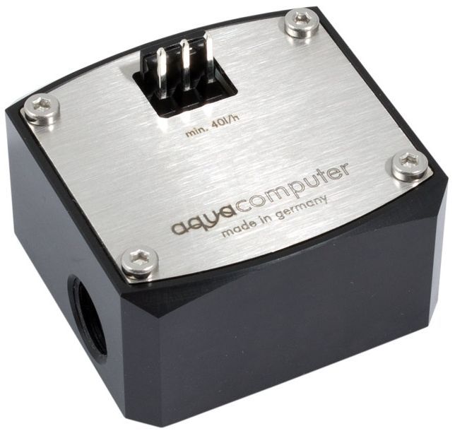
Aqua Computer relies on an Acetal body with the usual 1/4" connectors, a stainless steel cover and a gyro (with 2 magnets on the vane) for flow measurement, and Digmessa Hall sensors to determine the number of revolutions. This means that the device belongs to the so-called vane wheel or Turbine flow sensors. On the credit side of this principle are the good repeatability and sensitivity in response, a comparatively simple design at a reasonable price, the compact design and the very large measuring capacity.
However, there are also disadvantages, because these sensors are very sensitive to foreign bodies (susceptible to constipation), require regular maintenance due to high sash wheel speeds (axial wear) or replacement of the vane wheel after a certain number of operating hours. With 169 pulses per litre, the sensor is already relatively high-resolution. The manufacturer writes on the homepage from a range from 40 l/h to 1500 l/h, i.e. a maximum of 25 liters per minute, which is rather utopian for normal home use. Other documents assume a maximum of 600 l/h, which seems rather plausible.
The specified tolerance of +/2 percent (i.e. actually four) is still to be tested. The 3-pin connection on the top is used for the 5V power supply, the ground connection and the output of the speedometer signal. For the test of the Aqua Computer "High-Flow" I use one of the devices specified as compatible in the form of the Aqua Computer aquaero 6 Pro, so still the model with the real buttons, which I connected to the 12-V molex of a mobile Phobya power supply.

Test system and test conditions
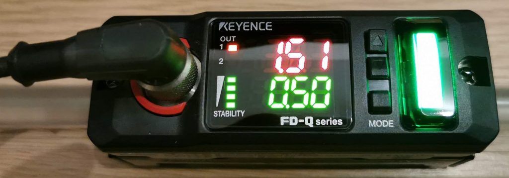
Since I also want to measure (and compare) flow meters in the future (but not only), I rely on a well-defined measurement structure, which is not "picked apart" in the meantime. The centerpiece is a special, high-precision ultrasonic flow meter in the form of the Keyence FD-Q10C. This clampable flow meter works completely non-contact and does not affect the flow in the circuit. The accuracy far exceeds that of the mechanical solutions, so that here after calibration one gets a real reference value for the current volume flow.
The whole thing is fed via a special 4-pin M12 cable from an external power supply. In order to meet the pipe section used under the clamp exactly, I had the assembled components matched once again in a friendly laboratory in a series circuit to a calibrated device. The current volume flow is generally measured in litres per minute (l/m), not per hour. In addition to the limit value determination, the device also offers differential measurements and a freely definable zero point.
The trick in generating the flow volume in my measurement setup is not to regulate the pump, but to run constantly at a fixed speed. Thus, the characteristics of their behaviour remain even under back pressure. I can achieve the reduction of the volume in the measuring circuit by two methods. First, a bypass is opened in front of the measuring circuit until the volume is slightly above the required value. Only then is a very precise valve (with screw reduction) in series closed to the extent that the exact value of the FD-Q10C is reached.
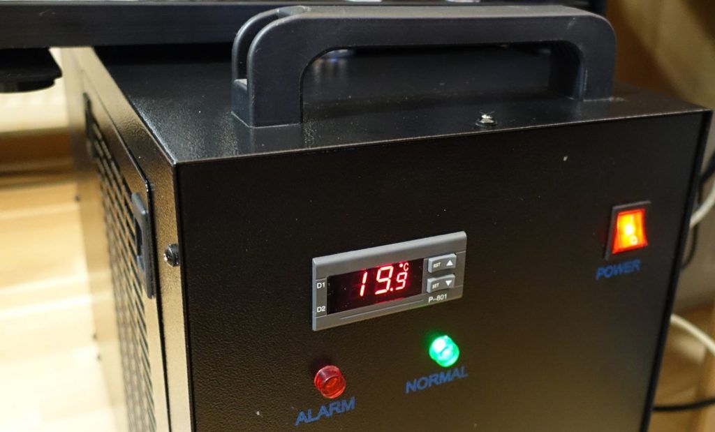
The inaccuracy here is approx. 0.01 l/m to the measured value. Since the pump gets as little back pressure as possible due to the bypass and a total of 12 litres of water, which also have a constant 20 °C water temperature over the entire test period due to the chiller, ensure a good balance, the fluctuations of the flow to a minimum. I measure the instantaneous volume flow with the keyence at 0.5-second intervals and a slight hysteresis for smoothing.








Kommentieren