binary. I use hexdump instead of cat.sollte in hex bzw binary sein.
Du verwendest einen veralteten Browser. Es ist möglich, dass diese oder andere Internetseiten nicht korrekt angezeigt werden.
Du solltest ein Update durchführen oder einen alternativen Browser verwenden.
Du solltest ein Update durchführen oder einen alternativen Browser verwenden.
AMD RED BIOS EDITOR und MorePowerTool - BIOS-Einträge anpassen, optimieren und noch stabiler übertakten | Navi unlimited
- Themenstarter Igor Wallossek
- Beginndatum
Hex is just another way to look at binary data. 4 bits (binary digits) are one digit in hexadecimal.
To your question, i can't give you a complete answer. But i can give you some data here..
the offset of this byte is 0x67F
this one would be at offset 0x734
Update:
Beide Bytes sind (noch) nicht im MPT inbegriffen, werde ich mal auf die Liste setzen. Wenn ihr schon damit experimentieren wollt, Hexeditor (ich kann HxD empfehlen) nutzen, .mpt-Datei laden und dort aufs Offset nochmal 0x100 dazu zählen. Speichern, ins MPT laden und in die Registry schreiben oder Registry-Datei erstellen. Alle nicht im MPT anwählbaren Daten bleiben selbstverständlich erhalten.
To your question, i can't give you a complete answer. But i can give you some data here..
Code
:
uint8_t GfxclkSource; // 0 = PLL, 1 = DFLL
Code
:
uint8_t dBtcGbGfxDfllModelSelect; //0 -> fused piece-wise model, 1 -> piece-wise linear(PPTable), 2 -> quadratic model(PPTable)Update:
Beide Bytes sind (noch) nicht im MPT inbegriffen, werde ich mal auf die Liste setzen. Wenn ihr schon damit experimentieren wollt, Hexeditor (ich kann HxD empfehlen) nutzen, .mpt-Datei laden und dort aufs Offset nochmal 0x100 dazu zählen. Speichern, ins MPT laden und in die Registry schreiben oder Registry-Datei erstellen. Alle nicht im MPT anwählbaren Daten bleiben selbstverständlich erhalten.
Zuletzt bearbeitet
:
Veii
Veteran
- Mitglied seit
- Okt 24, 2021
- Beiträge
- 184
- Bewertungspunkte
- 212
- Punkte
- 43
@Veii scheint die kurve entschlüsselt zu haben.
Nun hab ich es korrektDas bestätigt das die rdna2 kurve nichts mit der alten Formel zu tun hat.
Mehr ein wenig später mit weniger halbwissen
Was wäre diese "alte Formel" ?
Es ist PLL droop & AVFS balancing , auf PSM-Margins. Ne Zwiebel
@PJVol i'll assist a bit later
Struggle to understand DFLL & PLL behavior of clocksync
https://www.allaboutcircuits.com/te...es-exponential-and-piecewise-linear-analysis/ and how this functions
But you are right


It's multi layered
Give it time and i'll put a more technical writeup out
If friend is not faster.
Still need to find LkgID data
RedF
Urgestein
f(x)=a·x²+b·x+cNun hab ich es korrekt
Mehr ein wenig später mit weniger halbwissen
Was wäre diese "alte Formel" ?
Es ist PLL droop & AVFS balancing , auf PSM-Margins. Ne Zwiebel
RX480
Urgestein
- Mitglied seit
- Feb 13, 2020
- Beiträge
- 1.877
- Bewertungspunkte
- 871
- Punkte
- 114
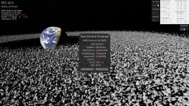
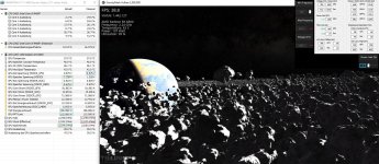
.... mein Sommersetting für die 6800 ist jetzt bei ca. 109W avg. (tgp) bei nem PL von 153W (tgp)
just for fun, komme jetzt auch ohne Taktbegrenzung im Gravity auf Wattspitzen nahe am PL=115W (tgp), ... durch PL=-8 !?Mit der RX6900XT und dem langsamsten Profil (Taktbegrenzung) bei rund 100-107Watt schaut es schon völlig anders aus.
... ist also jetzt net mehr so, das Gravity das PL net ausnutzen kann, warum auch immer, ... funzt auch in der UE5-Demo
das aktuelle Setting ist jetzt 6mV höher im MPT als das Alte, ... solange die Watt reichen, why not
(muss vermutlich dann nur in Games die Settings für Licht+Schatten etwas reduzieren, damits im Teilllastmodus bleibt, ... ansonsten
brauche ich für heavy Games dann nur das PL von -8 auf +15 erhöhen, quasi Spielraum mit 2 WM-Settings von 115W bis 144W, ... ohne
das MPT nochmal anfassen zu müssen)
edit: das PL-8 wird nach m.E. auch korrekt vom Treiber erkannt,... z.Vgl. kurzer Schnappschuss mit HW-Info in Bild3
Anhänge
-
 Gravitybench2273@893-816_2046FT_TDV768_fclk1500.jpg1,5 MB · Aufrufe : 10
 -
 [email protected]1,6 MB · Aufrufe : 11
 -
 Gravity2273@893-818_2046FT_TDV768_fclk1500.jpg444,5 KB · Aufrufe : 17
Zuletzt bearbeitet
:
Thanks, l've looked at it. Indeed, clock source is DFLL and prefered droop model is piecewise linear (correct offset for the GfxclkSource is 0x0680 ).Hex is just another way to look at binary data. 4 bits (binary digits) are one digit in hexadecimal.
To your question, i can't give you a complete answer. But i can give you some data here..
the offset of this byte is 0x67FCode :uint8_t GfxclkSource; // 0 = PLL, 1 = DFLL
this one would be at offset 0x734Code :uint8_t dBtcGbGfxDfllModelSelect; //0 -> fused piece-wise model, 1 -> piece-wise linear(PPTable), 2 -> quadratic model(PPTable)
Update:
Beide Bytes sind (noch) nicht im MPT inbegriffen, werde ich mal auf die Liste setzen. Wenn ihr schon damit experimentieren wollt, Hexeditor (ich kann HxD empfehlen) nutzen, .mpt-Datei laden und dort aufs Offset nochmal 0x100 dazu zählen. Speichern, ins MPT laden und in die Registry schreiben oder Registry-Datei erstellen. Alle nicht im MPT anwählbaren Daten bleiben selbstverständlich erhalten.
So back to the prev point, is there a chance we could edit Overdrive table in MPT? As far as I could see it is not part of the driver dedicated PP_Table.
Mostly interested in these values, especially VddGfxOffset (ain't it nice to have a completely "wattman-less" tuning tool?):
Code
:
typedef struct {
  uint16_t               GfxclkFmin;           // MHz
  uint16_t               GfxclkFmax;           // MHz
  QuadraticInt_t         CustomGfxVfCurve;     // a: mV/MHz^2, b: mv/MHz, c: mV
  uint16_t               CustomCurveFmin;      // MHz
  uint16_t               UclkFmin;             // MHz
  uint16_t               UclkFmax;             // MHz
  int16_t                OverDrivePct;         // %
...
  int16_t                VddGfxOffset;         // in mV
...
} OverDriveTable_t;
drivers/gpu/drm/amd/pm/swsmu/inc/pmfw_if/smu11_driver_if_sienna_cichlid.h · drm-next-5.19 · Alex Deucher / linux · GitLab
freedesktop.org GitLab login
 gitlab.freedesktop.org
Thanks, Alas! )Give it time and i'll put a more technical writeup out
If friend is not faster.
Is your friend Sam Naffziger by any chance?
Zuletzt bearbeitet
:
The structure used in the PowerPlay_Info Table (the name of the real Data Table) is not found in the driver_if :
So the PPTable_t is a structure inside the PowerPlay_Info Table. The overdrive_table is somehow the same structure, but there are two of them, for the maximum and minimum, for the actual overdrive settings. With Overdrive 8 you can set these values for the OverDriveTable_t structure for the SMU. So, you already can edit these values with MPT (Overdrive tab), which are the min/max from the PowerPlay_Info Table (=SPPT), and with MCU you can edit the actual settings for the driver, which would be the structure form your link.
RDNA1 has the OD8_GFXCLK_CURVE feature enabled, where the RDNA2 only has OD8_GFXCLK_FMAX / OD8_GFXCLK_FMIN to set. I don't know what the driver makes of it, but i guess the min/max is the way to go for RDNA2, i wouldn't want to force it back to RDNA1 methods.
smu_v11_0_7_pptable.h - drivers/gpu/drm/amd/pm/swsmu/inc/smu_v11_0_7_pptable.h - Linux source code (v5.19.1) - Bootlin
Elixir Cross Referencer - Explore source code in your browser - Particularly useful for the Linux kernel and other low-level projects in C/C++ (bootloaders, C libraries...)
elixir.bootlin.com
RDNA1 has the OD8_GFXCLK_CURVE feature enabled, where the RDNA2 only has OD8_GFXCLK_FMAX / OD8_GFXCLK_FMIN to set. I don't know what the driver makes of it, but i guess the min/max is the way to go for RDNA2, i wouldn't want to force it back to RDNA1 methods.
Damn, it took me a while to realize you're talking about ADL, and not amdgpu, lol.RDNA1 has the OD8_GFXCLK_CURVE feature enabled, where the RDNA2 only has OD8_GFXCLK_FMAX / OD8_GFXCLK_FMIN to set
OD gfx min/max is there in navi10 headers, I believe they're just ignored if related feature is disabled:I don't know what the driver makes of it, but i guess the min/max is the way to go for RDNA2, i wouldn't want to force it back to RDNA1 methods.
C++
:
static int navi10_od_edit_dpm_table(struct smu_context *smu, enum PP_OD_DPM_TABLE_COMMAND type, long input[], uint32_t size) {
...
    switch (type) {
    case PP_OD_EDIT_SCLK_VDDC_TABLE:
        if (!navi10_od_feature_is_supported(od_settings, SMU_11_0_ODCAP_GFXCLK_LIMITS)) {
            dev_warn(smu->adev->dev, "GFXCLK_LIMITS not supported!\n");
            return -ENOTSUPP;
        }
        if (!table_context->overdrive_table) {
            dev_err(smu->adev->dev, "Overdrive is not initialized\n");
            return -EINVAL;
        }
...Yeah, it works fine, and would definitely fit as the MPT upgrade.with MCU you can edit the actual settings for the driver
https://elixir.bootlin.com/linux/v5.19/source/drivers/gpu/drm/amd/pm/swsmu/smu11/navi10_ppt.c#L2578
Zuletzt bearbeitet
:
Veii
Veteran
- Mitglied seit
- Okt 24, 2021
- Beiträge
- 184
- Bewertungspunkte
- 212
- Punkte
- 43
Another friendThanks, Alas! )
Is your friend Sam Naffziger by any chance?
")
Got to know that piece-wise linear model is not exactly used & up to SKU
It works if defined, but by stock is not
I think curve told
Is Quadratic Model , or SpeedShift model ?f(x)=a·x²+b·x+c
Makes me wonder why AMD has to implement 4 DFLL models
Also it's fascinating to see that 6x50XT lineup actually got work put, to remake it
It's not just an LC REF to 6950XT change, with barely any chip & chip-bios defined changes
Other 6x50 lineups actually have fully remade curve and offsets. Nothing copy pasted or reused (started from scratch)
[PATCH 10/64] drm/amdgpu/gfx10: convert to IP version checking — Linux AMD GFX
AMD GFX: [PATCH 10/64] drm/amdgpu/gfx10: convert to IP version checking
www.spinics.net

I keep getting told MPT is outdated,
But my opinion is a bit different. It's lack of cooperative work, that's all
Everyone focuses on their projects. I'm borrowed somewhere else, all i can say is soon it's all fine and equal ground
My part is digging in bios & playing with toys/curve, friends part is researching curve and focusing on access
Hopefully my part, cheese cutting away RSA check, makes more progress
* borrowed with limited teaching, rather curve/clock experience used ~ but restricted information access
But at least with SOC curve focus, now mem till 2537 works ~ that makes me happy. Progress is made

Here reposted again, soo 6900XTXH users can copy SOC curve
As basic as it gets ~ ignore GFX, lack of LkgID access makes universal curves building more than troublesome
// it's a mess that only works on my card but needs more positive on B for other cards
SOC at least i can confirm is correct for 2448 strap (daily) ~ on 16gbps and 18gbps models
// nothing fancy on voltages or other freq changed, should be replicable
... i think also for 6800 users it could be fine, except for timings difference and clock restriction. Voltages should be fine

Anhänge
Zuletzt bearbeitet
:
I beleive other three is either legacy/backup or for the not yet released SKUs.Makes me wonder why AMD has to implement 4 DFLL models
If I get it right, current AVFS model actually don't need any fuses and their BTC correction with some quadratic transfer function for each voltage island, since DFLL together with the adaptable voltage margin approach solves most of the problems, such as VFT variation and AC noise dependency, and other timing issues.
Veii
Veteran
- Mitglied seit
- Okt 24, 2021
- Beiträge
- 184
- Bewertungspunkte
- 212
- Punkte
- 43
Can you tell me a bit more on the BTC topic. I struggle to understand 4 thingsI beleive other three is either legacy/backup or for the not yet released SKUs.
If I get it right, current AVFS model actually don't need any fuses and their BTC correction with some quadratic transfer function for each voltage island, since DFLL together with the adaptable voltage margin approach solves most of the problems, such as VFT variation and AC noise dependency, and other timing issues.
GFX DFF BTC
FLL BTC for L3
FLL itself for resume
& DC BTC as a functionality/sensor itself
It follows PSM Margins. Has a fixed range
And appears that many voltage values depend on it
DC BTC is odd,, i miss information
Too much bitcoin search results to figure out it's real usage)
EDIT:
Soo, DC-, tolerance & bus tie contactor
Both droops based on voltage islands of AVFS ~ withing margins allowed ?
Higher value, more constant supply?)
You surely know what a bus tie contactor does ?
Later/Default value is "per-sku based".I beleive other three is either legacy/backup or for the not yet released SKUs.
Idk what i can spoiler, but Piece-Wise Linear. droop is not working on 6700/6750 ~ but it might change
Zuletzt bearbeitet
:
Don't forget the DPM descriptors:
Code
:
DpmDescriptor_t DpmDescriptor[13];
typedef struct {
  uint8_t        VoltageMode;         // 0 - AVFS only, 1- min(AVFS,SS), 2-SS only
  uint8_t        SnapToDiscrete;      // 0 - Fine grained DPM, 1 - Discrete DPM
  uint8_t        NumDiscreteLevels;   // Set to 2 (Fmin, Fmax) when using fine grained DPM, otherwise set to # discrete levels used
  uint8_t        Padding;
  LinearInt_t    ConversionToAvfsClk; // Transfer function to AVFS Clock (GHz->GHz)
  typedef struct {
  uint32_t m;  // store in IEEE float format in this variable
  uint32_t b;  // store in IEEE float format in this variable
  } LinearInt_t;
  QuadraticInt_t SsCurve;             // Slow-slow curve (GHz->V)
  typedef struct {
  uint32_t a;  // store in IEEE float format in this variable
  uint32_t b;  // store in IEEE float format in this variable
  uint32_t c;  // store in IEEE float format in this variable
  } QuadraticInt_t
  uint16_t       SsFmin;              // Fmin for SS curve. If SS curve is selected, will use V@SSFmin for F <= Fmin
  uint16_t       Padding16;
} DpmDescriptor_t;Where did you see "GFX DFF BTC"? Have never seen that. FLL is common term, DFLL - is fully digital frequency locked loop.Can you tell me a bit more on the BTC topic. I struggle to understand 4 things
GFX DFF BTC
FLL BTC for L3
FLL itself for resume
& DC BTC as a functionality/sensor itself
It follows PSM Margins. Has a fixed range
And appears that many voltage values depend on it
DC BTC is odd,, i miss information
Too much bitcoin search results to figure out it's real usage)
EDIT:
Soo, DC-, tolerance & bus tie contactor
Both droops based on voltage islands of AVFS ~ withing margins allowed ?
Higher value, more constant supply?)
You surely know what a bus tie contactor does ?
BTC stands for Boot Time Calibration, it runs every boot to calibrate various fuses or previously stored values, for example used in interpolating three points VT model - VTmin, VTinversion, VTmax exploiting the temperature inversion.
All DcBTC values supposedly used by SMU to determine target voltage for a certain IP block according to previously established or fused guardbands (gb).
DC Tolerance may refer to additional gb gained relative to AC ones defined at ATE, but I'm not sure.
And they could well correlate with the corresponding PSM margins, which initially could be used to determine Vmin for the PSM input to update fused counts with the values it generated, and which are SMU takes into account later.
Never heard of "bus tie contactor", sorry ))
Don't know yet what exactly SS-model is, but SS usually referes to a process corner in FET design. I can assume that SS FETs (slow NFET and slow PFET) has higher switching capacitance and so lower work frequencies.
Zuletzt bearbeitet
:
Veii
Veteran
- Mitglied seit
- Okt 24, 2021
- Beiträge
- 184
- Bewertungspunkte
- 212
- Punkte
- 43
I thought it is SpeedStep or SmartShift"SS" means "Slow-slow curve (GHz->V)" in AMD language.
They indeed are not good with names
@PJVol Thank you for the explanation
PSM falls into it too, as it has upper boundries and is read as some kind of constant voltage value or margin
I'm not exactly confident on it, as all i find about DFLL and PLL ~ have to do with ext clock crystalsDC Tolerance may refer to additional gb gained relative to AC ones defined at ATE, but I'm not sure.
Take a look at this dump
Anhänge
Here you can learn about dfll on the example of "some embodiment"
() - FLL_V4-14fev.pdf
Though I beleive AMD uses slightly different approach, such as sensor (or frequency sampler in their terminology) implementation and etc
And the purpose of FLLs seem to me quite the opposite of what the external clock source is intended for.
() - FLL_V4-14fev.pdf
Though I beleive AMD uses slightly different approach, such as sensor (or frequency sampler in their terminology) implementation and etc
And the purpose of FLLs seem to me quite the opposite of what the external clock source is intended for.
Zuletzt bearbeitet
:
What does DfllModel 3 mean? Per part piecewise linear? The same as for the Navi 23.Take a look at this dump
Veii
Veteran
- Mitglied seit
- Okt 24, 2021
- Beiträge
- 184
- Bewertungspunkte
- 212
- Punkte
- 43
Model 3 is undocumented,What does DfllModel 3 mean? Per part piecewise linear? The same as for the Navi 23.
0 = fused on chip piece-wise
1 = ROM per chip & PP Table offset ~ piece-wise
2 = quadratic PP Table model converted to AVFS
3 = undocumented and dynamic
I'm sorry ~ give it 1-2 weeks more
Thank you for the document, i'll try to study it

Interesting is SS section looks to be per frequency with quadratic model
Mostly interesting from last days is:
~ not only VMAX per curve limits GFX VMAX & has F-MAX targets , which driver follows (PP Table)
~ Bioses for 6800, 6900, 6950 SKU come with same per-chip calibration offsets/limit, just with different post AVFS offsets
(same V/F, different higher range, soo different main offset ?)
~ MEM limit is a DPM strap limit , unclear if still timing issue on non 6X50 bioses sub 6800 SKU // annoyingly encrypted but not Bios RSA
~ SOC curve somehow is messy ?, UCLK issue ? , it is not IMC nor MVDD (mem) that limits back MCLK OC & translates perfectly between 16 & 18gbps models (not special binning)
It does look to be a driver peak voltage issue that limits higher voltage and higher limits in general
But i somehow refuse to believe. Actually it might make sense if it fails AVFS and falls back to 500MHz failsafe.
Also what is GamingClk
I don't think Navi 23 is allowed to use piece-wiseThe same as for the Navi 23.
Navi 22 is not unless something is bugged.
Also "guess" that Navi 22 is newer than 21 xx50, in the featurset.
All i can see is that curve changes from Bios + LkgID calibration (RTC?) & additive offsets
Soo Navi 21 on piece-wise #1 , if selected ... on KXTX , have a better SOC curve for example ~~ but should behave identical in GFX (where is VMAX limit really??)
(mostly the change between 6900 v071,6900REF v060, 6950 v071)
But 22 and very likely (sorry i have zero here) , Navi 23 ~ are different
They are not operating on #1 DFLL
Zuletzt bearbeitet
: