


Voltage transformer losses
This is a vexing and recurring theme, because analogous to the normal ATX power supply, the efficiency of these DC/DC converters is never 100% and is even significantly below the efficiency of a good 80-plus power supply when switching on the board. The reasons for this are manifold and are also due to the broader range of subjects in different phases. While the 12-volt strand of a normal ATX power supply with thick low-impedance capacitors and some like self-left solid capacitors can be used, voltages around 1 volt (and below) including the almost huge currents require complete other circuit layouts.
The voltage converters (low- and high-side) are either discreetly constructed as single or dual MOSFETs, or rely on so-called smart power stages. Depending on the circuit design, component selection, switching frequency and of course the cooling, the theoretical efficiency at this point is still approx. 90% or even something above. However, a larger number of phases also causes problems, as the losses spread more widely.
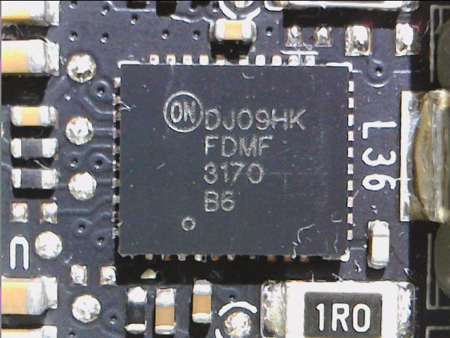
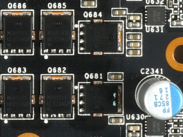
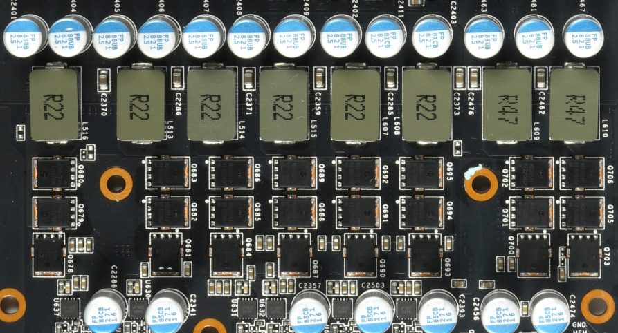
It is no coincidence that Nvidia has moved away from so-called phase doubling, where the up to eight real phases that such a PWM controller can provide have been virtually doubled by using so-called doubler chips by simply using the newly generated phase. phase-shifted. In the meantime, however, there are also PWM controllers that allow the parallel and thus phase-like operation of several voltage converter circuits. In the following image we see on the left a highly integrated Smart Power Stage (SPS) with integrated high- and low-side, as well as gate driver and Schottky diode. On the right we see two discretely constructed phases with one MOSFET each on the high-side (Q681 and Q684) and a pair working in parallel on the low-side (Q686+Q685 and Q683+Q682), as well as an external gate driver (U630 and U631) each
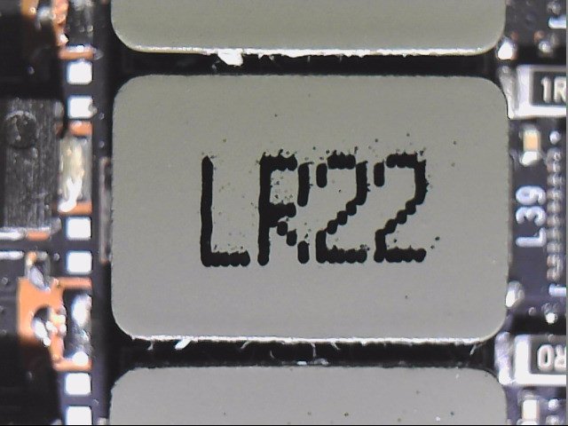
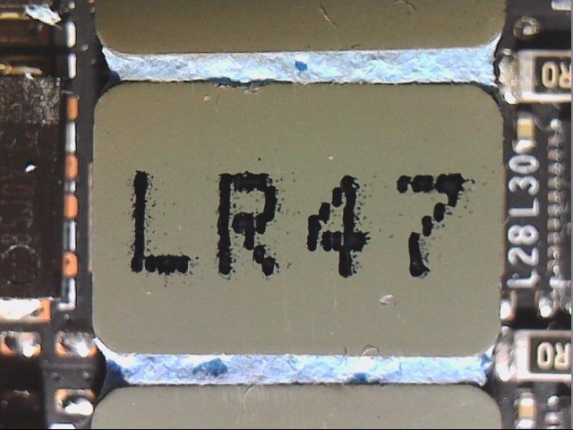
However, since you can no longer do with capacitors alone to get a high-quality and ripple-free voltage at the end of the PWM nodes, the smoothing of each voltage converter circuit is realized with an LC link (coil + capacitor). These coils have both an electrical and an inductive resistance, which pushes the efficiency down again significantly. Sounds insoluble, by the way, it is also, because you cannot increase the cross-sections of the windings endlessly. Especially since the inductance remains yes. In the image below, we see on the left a typical coil for the GPU phase and quite a one with higher memory inductance.
In addition, of course, there are also synchronisation and balancing problems, the more phases you get so messed up. In the meantime, however, the PWM controllers are able to intelligently control the utilization and utilization of the phases in the event of low and partial loads. Nevertheless, in the end, an average efficiency of 78 to 85% remains for the entire board and all voltage converters working on it (GPU, memory, SoC, partial voltages, peripherals, etc.), nothing more. The RTX 2080 Ti from our example absorbs a total of 275 watts of power, but can only do about approx. 228 watts. Here alone 47 watts of waste heat are lost in the power supply of the whole sources, no matter how the whole thing is divided afterwards!
The glass voltage converter – DCR
In order to secure the balance and to be able to control the individual control circuits, a special procedure is required. The keyword is DCR (Direct Current Resistance). In the end, each component has very specific characteristics in this respect. But to shorten it: DCR is the basis for calculating or measuring temperatures and currents. But how does the controller know exactly which currents flow in which control loop? Monitoring can be different, because there are – who wonders – different methods for doing so.
In my article "Nvidia GeForce RTX 2080 Ti – Internal details about power supply, deviating components and where the spikes have remained" I had praised Nvidia's reference design for the power supply, and rightly so. There you also read something about the Smart Power Stages (SPS) and IMON (power), but at that time I had given myself certain details. I'll add them now, because IMON is exactly what the so-called MOSFET DCR (DrMOS) provides!

The picture above shows the typical layout with the intelligent PLC, which provide the current value for each individual control circuit with IMON, which is so urgently needed for perfect balancing, i.e. the balance between the phases. How do the PLC determine this value? The drain currents of the MOSFETS are measured in real time and these values are also extremely accurate (in the example above 5 A/A signal).
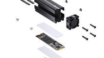
This very cost-intensive solution replaces the significantly cheaper Inductor DCR, i.e. a current measurement via the inductive resistance of the respective filter coils in the output range. For example, Nvidia uses such a solution for inexpensive maps (symbol image below), where it is a little more leisurely when it comes to the flow of electricity. However, the accuracy of this solution is significantly lower and is also strongly influenced by fluctuations in the component quality. Too big tolerances can quickly tip the complete balance!
The quality of the coils is always such a story in itself and it also explains why problems and inaccuracies occur again and again. AMD has relied on this Inductor DCR for years, but it is no more than a rough estimate and is becoming increasingly inaccurate, especially at higher temperatures. Only the Radeon VII uses (all the more expensive) PLC from International Rectifier and thus for the first time fully MOSFET DCR for the important voltage control circuits.
All this has only indirectly to do with the voltage converter losses, but it helps the controller with the optimal control and monitoring of the phases. This prevents or reduces overloads and hotspots, and in the end, of course, efficiency benefits. That's why I included this section. Let's get to the final bill on the next page, because it's going to be interesting!


Kommentieren