How do latencies actually arise?
In order to understand the meaning, one must of course first dive a little deeper into the system. Let’s therefore first look at the mouse and the tortuous path from the player’s actual click to the finished rendered pixel on the screen. In contrast to PS/2, current mice are mostly attached to the USB, with all the advantages but also the disadvantages of access and transfer rate. Since the USB is operated in so-called polling mode, there are no actual interrupts for a device, unlike PS/2.
However, a connected USB mouse can, if it wants to report an action, provide an interrupt packet that is returned to the host immediately after receiving an IN token. The host responds with an ACK and executes the interrupt. If no interrupt should be executed, the function provides a NAK. The problem now arises when there are a lot of such packages in a very short time, e.g. when a skilled player falls prey to extreme clickmatism.
Theoretically, the USB can also suffer from speed problems when many devices are connected at the same time. So if, for example. If keyboard, printer, scanner and webcam are connected to the same USB controller and want to transfer data at the same time, then it can get quite tight and the first waiting times will occur. Because these devices have to share the possible bandwidth. The connection (pipe) to a device knows four types of data transmission:
– The control transfers (error correction)
– Bulk transfers (large amounts of data during scanning, printing, file copying, bus load up to 100%)
– Interrupt transfers (e.g. Keyboard, mouse)
– Isochronous transfers (voice, video, multimedia, bus load maximum 80%)
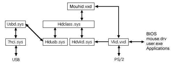
Technically it would be possible to guarantee exclusive bandwidth reserves and minimum latencies for the interrupt transfers on the bus, but unfortunately normal USB controllers do not offer this for individual ports or devices. A special solution would have to be developed here, which would certainly not be really cheap and would also be out of proportion to the effort involved. Since Win32, every keyboard information meanders through a jumble of layers and drivers, unfortunately:
But the USB with connected mouse (red) alone is not the whole process, as the following block diagram shows. This is because, in addition to the so-called “peripheral latency”, the own computer with the “PC latency” and the “display latency” also play an important role in this causal chain of delay, which could also be called “end-to-end system latency”. Again, for the rest, I would like to explain the most important areas for all those who do not immediately get along with the abbreviations and designations of the scheme.
Some of the areas in the scheme where latency occurs are more important than others. The render queue and the GPU form one of these areas, which is called “render latency”. While reducing the screen resolution and/or the game graphics settings can certainly reduce the render latency (not necessarily preferred), a faster GPU is probably the best choice. And if you’re looking at the upcoming launches for graphics cards and processors, you’ll know why I’m picking on them a bit.
Besides the GPU there are also important tasks for the CPU like game simulation processing, the render submit and the graphics driver, which runs on the CPU – all this is primarily influenced by the speed of the CPU. If you notice latencies in the game, which aren’t caused by the graphic card or the display, you’ll also need a faster CPU. But since we are not in the sales thread here, I better get back to the block diagram and the individual stations:
- Mouse HW – This is defined as the first electrical contact that the mouse detects. In the mouse, however, there are already some routines (e.g. Debounce), which can increase the latency until the reported pressing of the mouse button.
- Mouse USB HW – The mouse must wait for the next request to send the packets. This time is played back in USB HW.
- Mouse USB SW – Mouse USB SW is the time in which the operating system and the mouse driver process the USB packet (see also first schematic for the signal path through the software layer).
- Sampling – This section can grow or shrink depending on the CPU frame rate. Clicks can only be transmitted based on the operating system with a polling rate of max. 1000 Hz. This means that the click may have to wait until it can be captured and evaluated in the game. This waiting time is called sampling.
- Simulation (Sim) – Games must constantly update the state of the world. This update is called simulation. The simulation includes things like animations, game status and changes due to player input/interaction. During the simulation the mouse inputs are then also applied to the game status.
- Render Submission – Once the simulation finds out where and how to place things in the next frame, it starts sending render jobs to the graphics API runtime. The runtime environment then passes the actual rendering commands to the graphics driver.
- Graphics Driver – The driver is responsible for communicating with the GPU and sending command groupings to the GPU. Depending on the graphics API, the driver takes over this grouping (queue) for the engine or the engine itself is responsible for the grouping of rendering work.
- Render Queue – As soon as the driver detects the task, it is added to the render queue. The render queue is designed to keep the GPU constantly busy by keeping as much work as possible. However, this is always a bit at the expense of the latency, but also provides for a more even processing.
- Render – The time required by the GPU to render the entire task associated with a single frame.
- Composite – Depending on the display mode (full screen, borderless, windowed), the Desktop Windows Manager (DWM) may need to do some additional rendering work to composite the rest of the desktop for a given frame. This can also lead to additional latency. Therefore the (exclusive) full screen mode is always the first choice!
- Scanout – finally the flip takes place (the currently displayed frame buffer is moved to the newly completed frame buffer) and the actual scanout is planned. the scanout controls the display line by line, based on the frame rate of the display (monitor display)
- Display Processing – Display processing is the time taken by the display to process the incoming scan lines and initiate the pixel response.
- Pixel Response – This is the time that elapses from the time the pixel has received the new color value until the first noticeable change by LDAT (and the player as viewer).











Kommentieren