


The current now flows from the voltage converters to the GPU, whereby the additional inductance of the conductor tracks must be taken into account here. If you look at all the high frequencies (and the frequency mixtures that are created as a result), e.g. the remaining HF garbage of the voltage converters and the very fast changing loads (to which Boost reacts with voltage adjustments), then the supply voltage is anything but stable and smooth. Which brings us back to the beginning. In order to obtain the required voltage for a certain clock cycle, smoothing and buffering is required. And as close as possible to the GPU. That’s exactly why the capacitors, which are the subject of this article, are located directly on the back of the board under the BGA with the chip. And that’s where it gets interesting!
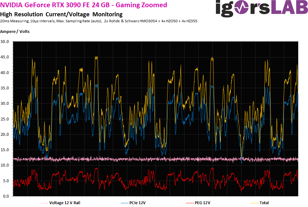
By the way it is wrong that the high clock rates of the GPU of e.g. 2 GHz or more below the GPU would still be detectable on the board. How many clock cycles a GPU runs through per second is only indirectly related to the problem. However, we already had the relationship between clock speed and voltage, as well as telemetry and control speeds. Here, control processes in the three-digit KHz range can be demonstrated, where e.g. voltages and frequencies are subject to changes. These changes, by the way, also work backwards again up to the voltage transformers and the 12-Volt supply rails.
For stable operation, the arbitrator naturally always requires that the appropriate voltage is applied for each boost clock that is enabled. However, if the load changes follow each other very quickly one after the other, there can be voltage drops below the GPU, if not buffered again appropriately. If this fails, one speaks of so-called voltage drops. If these occur only for a very short time, then the whole computer does not crash or the GPU freezes, but it starts with slight calculation or image errors up to the complete failure of whole cycles. Then only the respective program (game) crashes and you first land on the desktop again.
What is the difference between MLCC and SP-CAP or POS-CAP?
Many of the electrical data are rather unimportant for the following consideration. As long as the components are operated within the given specifications, not even the temperatures, resistances and other parameters are of primary interest. What really counts here is the speed of charging or discharging on the one hand, and the amount of what can be stored at all (capacity) on the other. The fact that engineers like to refer to all the polymer capacitors (regardless of their exact design) as POS-CAPs (and not just those from Panasonic) is simply due to the way these components are distributed and also because developers like to call them Piece-Of-Shit CAPs. What exactly was installed on the circuit boards as a polymer capacitor does not play a primary role in the mode of operation, because the principle is always the same for each variant.
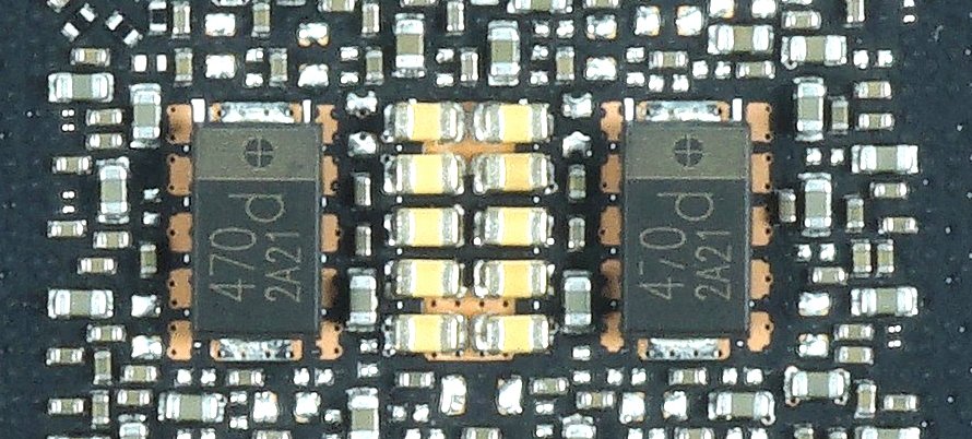
The following picture shows the mixed assembly of the Founders Edition for the supply of the core voltage (NVVDD). We see two polymer capacitors and a group of multilayer ceramic capacitors (MLCC). By the way, the difference between the types can be described quite nicely by using buckets. The polymer capacitor has the higher capacity. It is therefore the larger bucket, whose capacity is higher, but which also takes considerably longer to fill and empty. The group from MLCC is like many small buckets that can be filled and emptied more quickly. However, you need several groups that work simultaneously to store and release the same amount of water.
And what does this have to do with the GPU clock? Primarily nothing, because you don’t even notice it down here. That’s why I took the detour via telemetry when I explained it! But: the higher the clock frequency of the GPU and thus the required voltage, the sooner Boost will counteract and regulate. So the closer you get to the stored limit, the more frequent the corrections and also load changes become. The shorter the intervals become, the faster you have to be able to buffer. But that’s exactly where the small MLCC buckets come into play, which I already wrote that they are simply better in the high-frequency range because they are quicker.
The MLCCs are in fact the fine motorists and sprinters for buffering and filtering, the sluggish and rather cumbersome solids are the load carriers for the rough stuff. If the MLCC are missing, it becomes critical with very fast changes, because the supply voltage can drop below the required value for several cycles. However, the chip quality also comes into play here, since only standard values were stored in the firmware. Many GPUs are much better in terms of quality, so they actually need much less voltage to be stable.
By the way, you could do without solids as long as the capacity of the MLCC groups is sufficient for buffering. Here, of course, the quality of the upstream voltage transformers and coils or capacitors, as well as the routing of the conductor paths is also important. However, it is actually not possible to do without MLCC completely and only to a limited extent. Why is that? That’s where the quality of a GPU and binning come into play.
Conclusion and final remark
Owners of cards, which still run really stable despite six solids, owe everything to the very good chip quality. Owners of cards with MLCC, where errors still occur, may be annoyed about a GPU that does not even consistently cope with the stored voltage/frequency curve. This is exactly the point where the board partners couldn’t test anything at all with the first cards due to the lack of suitable drivers. There are certainly many cards in circulation here that would not have been suitable as OC cards.
The fact that NVIDIA has split the GPU’s power supply voltages between NVVDD and MSVDD also shows that they are well aware of the problem. I noticed that the MSVDD has much less changes and is generated independently from the NVVDD, so you should be able to get along with a well equipped MLCC group. So more MLCC does no harm if the rest of the layout allows this interpretation. Without it, however, becomes slow and sluggish.
I hope it wasn’t too complicated, even though some people will think that I simplified it too much again. But I am neither the Igorpedia, nor the high school for prospective layout and circuit board designers. It is all about the principle and understanding of what is happening here with these cards (if it is happening).


Kommentieren