Cooling Fans Reviews

It gets better and better – Scythe Kaze Flex 120 ARGB case fan up to 1800 RPM, lots of pressure, extreme thirst and surprisingly little noise

Fan measurement chamber and claim

And since there is currently no source that offers realistic and usable data, even in comparison, we have invested a lot of time and money and simply developed our own fan measuring station with the advice of a cooling unit manufacturer and then calibrated it. Here the colleague Pascal Mouchel has done a great job and the result as the model “Sarcophagus I” can be seen in the meantime. The heavy and solid body made of thick MDF boards is screwed, glued and sound-insulated. How it all works and what we can and cannot measure in the end, you will learn in this article.

By now most of it has materialized really nicely, also with a lot of good feedback from the community and technical help from some industry partners. Of course, what we can measure from now on only meets semi-professional requirements, even though all measuring instruments have been calibrated in an elaborate and cost-intensive way. But that’s enough for all areas of what concerns the PC self-construction and -conversion. Of course, we are not a standardization company or the TÜV, but we try to measure everything as accurately as possible, which still remains within a reasonably affordable range.


Measuring chamber with sound level control (measurement takes place separately)


A much simplified version with a long tube instead of the chamber would have been much cheaper, but it is so inaccurate due to the design that the values can only be considered as a rough estimate with many errors. The pressure drop is immense and a serious sound level measurement is simply impossible due to the resonance body thus created. Values below approx. 30 CFM can hardly be evaluated meaningfully and are then no longer particularly close to reality.

Tests as case fan and on radiators

Currently, there is always the question of what characteristics such a 120 or 140 mm fan really has. Not every model is suitable for all radiator thicknesses and many a supposed powerhouse loses so much pressure on radiators that it can hardly be called suitable. The data on volume flow (“throughput”) and static pressure in the data sheets are of no help if something works well on a slim radiator and fails completely on a 45 mm radiator.

In the picture we can see the middle partition between the two chambers, which supports the fan and also the radiator. Decoupling is of course very important, and we were fortunate to have expert help in calculating the volume for the chambers. Each of the chambers is also expediently lined with nubby foam and designed in terms of material technology so that there are hardly any disturbing influences.

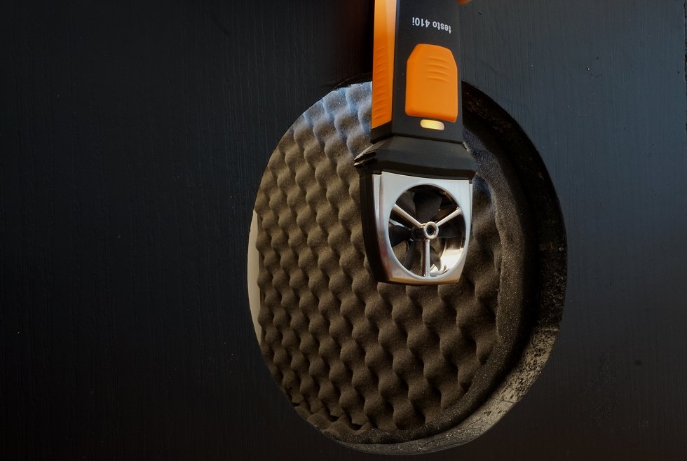
The “honeycomb” behind the fan was recommended to us by Black Noise and the cooling manufacturer. This means that all coolers are equally well integrated, because each has a different exit angle and this is exactly what can be compensated for. However, due to the honeycomb, there is no tear-off edge and the airflow is directed directly to the outlet.

Radiators and fans are decoupled and screwed down with their own clamping device. On the picture you can see very nicely the improvised clamp with thick washers and insulation material as a base. The control is done by an Aquaero from Aqua Computer, which we bought, so we can control and test the fans by voltage (DC) or by PWM. Both are needed, because many fans, some people don’t know, can’t be brought to the lower and upper limits of the speed range with pure voltage regulation and also show other anomalies, about which we will write something at the appropriate place.

Volume flow

We measure the volume flow at the outlet of the second chamber where the air is blown out. This range is covered relatively accurately by comparative measurements in the measurement set-up of the refrigeration partner, so that our testo 410i now delivers quite reliable results to the electronic measurement data acquisition, which correspond quite well with the reference data of the professional measurement. What is important here is not the price of the equipment, but the appropriate positioning and the exact calibration with series of comparative measurements.
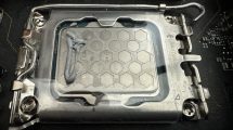
Static pressure

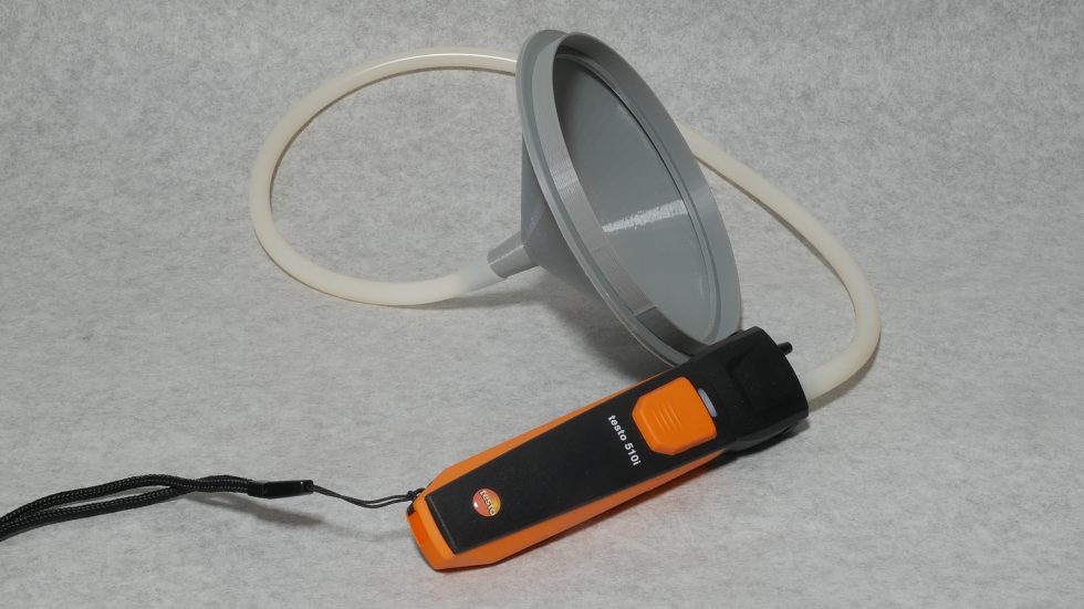
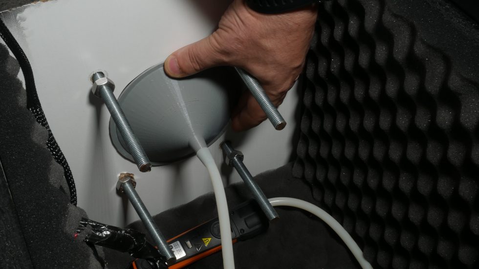
The measurement of the static pressure is carried out as usual as a differential pressure measurement. For this purpose, the special “bowl” is clamped on so that it closes airtight. Here too, of course, measurements were taken with borrowed, professional equipment and time-consuming calibrations were carried out. For this measurement we also use the 510i, a device we purchased ourselves from testo, and also collect the data wirelessly. Since many try to copy in the meantime, the angles in the 3D-graphics and also on the following two photos are of course not completely correct, because without knowledge of the exact dimensions of the funnel a copy is virtually senseless and it works also only in a quite small tolerance range really completely exactly. We have also made comparative measurement series for this once again. In practice, the whole thing looks like the two pictures below.

The installation is trouble-free and the pressure receptacle now also closes perfectly thanks to a special seal. The rest is just a matter of calibration, which we also did again. It’s unlikely to get much more accurate with semi-professional methods. However, especially in printing, mistakes are quickly possible, which above all are not immediately recognizable. Even if the deviations are small, we will still measure all previous fans again and prepare them for the database.


Noise emission

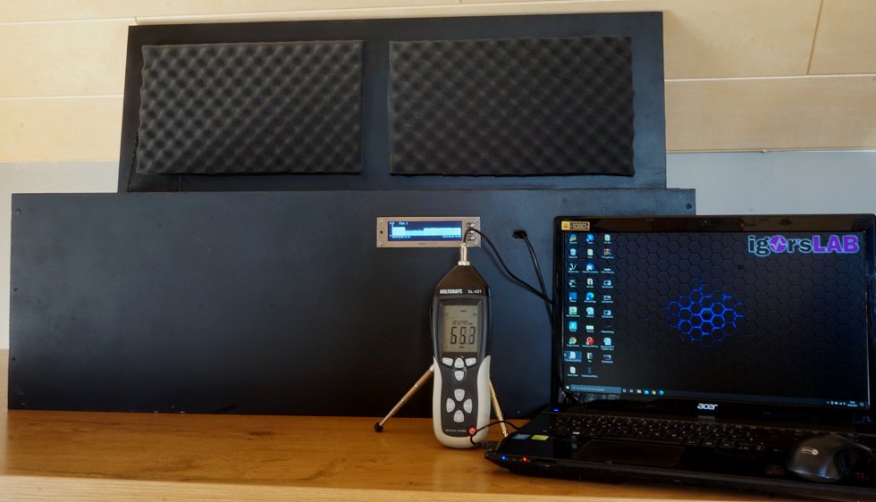
Measuring the noise level is a bit tricky, but works quite well in the evening hours at the measurement location. We decided to use dBA or dBC because values below one sone can hardly be measured reliably with still affordable and calibrated equipment and the software conversions of various software programs tend to confuse and become inaccurate in this low range. I’d rather use dBA then, especially since most people can do something with it. The measuring distance is 50 cm from the centre axis of the fan inlet.

We take two approaches to these measurements. For quick and plausibility tests we use a Voltcraft SL 451, which we calibrated according to ISO and whose microphone we placed decoupled from the body. The data acquisition takes place outside the measuring chamber. The Voltcraft SL 451 was kindly and uncomplicatedly provided to us by Conrad Elektronik. It is also the only component not acquired by ourselves. All other measuring instruments including accessories and electronics were purchased by us or provided from private stocks.

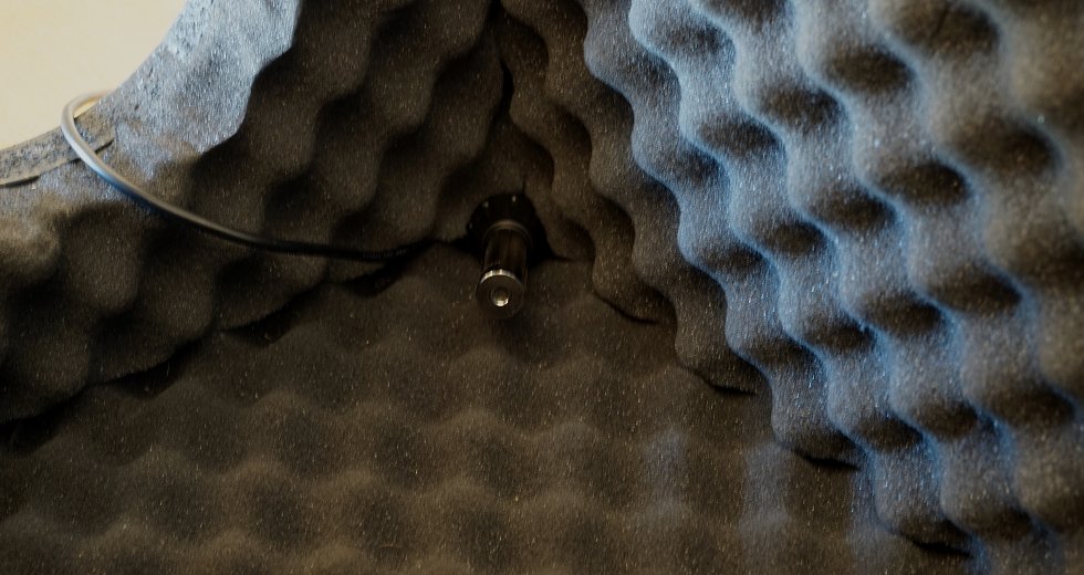
Our own purchases include a calibrated measurement microphone with XLR connector and low-noise USB interface. Measurements are taken in the evening and night hours in rural areas, so that one can already be quite satisfied with a basic level of below 26 dB(A). Since everything will be above this anyway during the measurement setup with a distance of 50 cm, this should not be a problem.

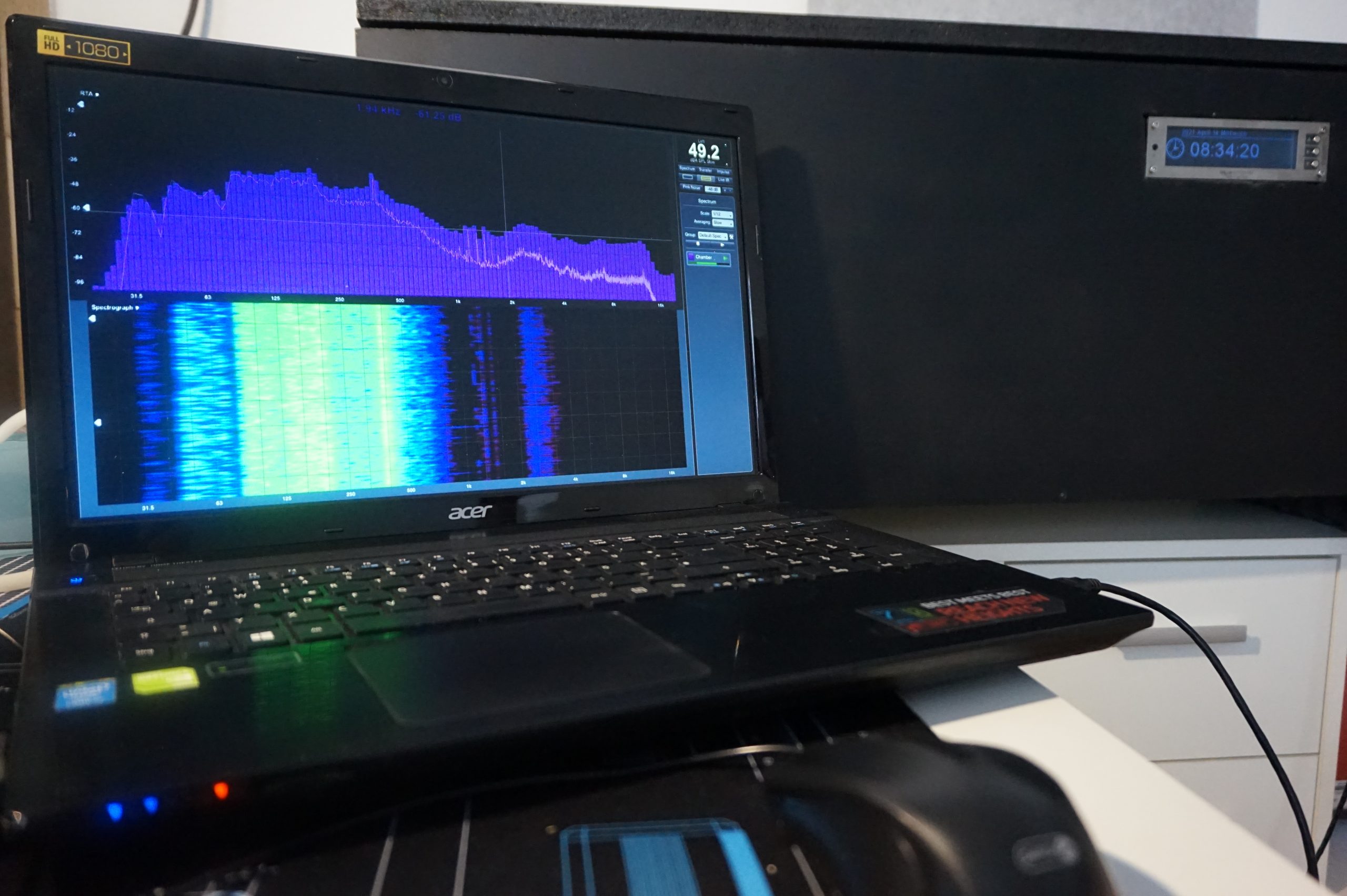
We also took the feedback from the community and evaluated the frequency band for each measurement, so you not only get the SPL values (sound pressure) in dB(A), but also a nice frequency analysis that helps to describe the sound character perfectly. Bearing or motor noise, vibrations or the tearing noise on the rotor – everything becomes mercilessly visible.

We will not go into certain details and approaches in this article, because there is still some foreign know-how in this structure and some things would probably be too far for the normal consumer. If you are interested and would like to build something like this, you are of course welcome to contact us. This also applies to all those who would like to contribute suggestions and tips, because we are still at the very beginning and can still correct or expand.

New metrics and graphics

Apart from the fact that we now also record the minimum and maximum values for the flowing currents and the power consumption, we have fulfilled two further wishes of the readers and extended the measurement series in this respect. In order to be able to assess the fans really objectively, we first graduated the resulting volume flow and measured the sound pressure level in many individual steps. The result for a fan then looks like this in comparison to the reference fan:

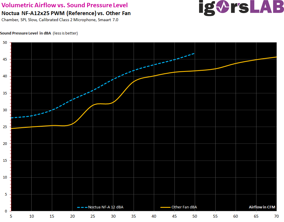
We see that the increase in the sound pressure level of our test fan is not as even compared to the reference, but the level is still lower at a comparable volume flow. In addition, the fan tested and compared here also delivers a significantly higher airflow due to a 50% higher maximum speed, which in the end is bought with a similar sound pressure level as the reference fan, but whose performance is significantly lower.

And because we just wrote about the rotational speeds, there are also new comparative graphics for this, at the express request of the reader, by showing which rotational speeds are necessary to achieve a certain volume flow. In practice, we can now also see where the dip in the upper graph comes from in terms of volume, because there is a speed range (rather a smaller window) where the fan doesn’t perform so perfectly and spins higher to reach the desired CFM than a more even rise in the curve would have led us to expect.


What we measure and how the result looks like, you can see on the next page by means of an exemplary selected fan, which however is anything but our reference. That’s exactly what we are still looking for 🙂

Test setup  
Housing / measuring chamber Two-chamber measuring set-up with sound insulation, fully air-conditioned room
Volume flow and flow velocity testo 410i (calibrated)
Differential pressure measurement testo 510i (calibrated)
Sound level measurement Measuring microphone Class 2 and USB interface, Smaart 7, Voltcraft SL 451 (Conrad, permanent rental, calibrated),
Speed control and fan control Aqua Computer Aquaero 6 Pro
Commissioning March / April 2021


Kommentar

Lade neue Kommentare

Zer0Strat

Veteran

162 Kommentare 138 Likes

Top, State of the Art Lüftertesting! Hast erstmal einen 10er per PayPal auf meinen Nacken gekriegt Igor. ^^

Antwort 2 Likes

Igor Wallossek

1

10,198 Kommentare 18,814 Likes

Danke! Da gibts mal wieder ein Kilo Barista von, das reicht dann wieder eine Woche für den Kaffeeautomaten :)

Antwort 2 Likes

Alexander Brose

Moderator

819 Kommentare 573 Likes

Sagenhaft!

Da sieht man, wer wirklich Spaß an seinem Job hat und ihn mit Leidenschaft ausübt (y)

#1 Adresse für professionelle Reviews.

Grüße!

Antwort 2 Likes

G
Guest

Interessant.
Aber die gemessenen 5 Watt+ pro Lüfter sind schon sehr arg, habt ihr ja auch geschrieben.
Bin trotzdem froh, dass ich mir die Noctuas gegönnt habe. Gerade im Mittelbereich, den man ja häufig ansteuert, ist mir das Klangbild auch gestürzt durch die Messwerte zu laut und brummig unruhig.
Abgesehen davon, dass ich froh bin kein RGB zu haben. Was natürlich interessant wäre, wäre ob die Lüfter ohne RBG-Firlefanz vielleicht nicht so die Schluckspechte sind? Naja so oder so. Das Brummige wäre nicht so meins, mein Rechner steht direkt rechts neben mir auf dem Schreibtisch... .
Aber das kommt natürlich immer auf den eigenen Anwendungsfall an. Supersilent sind sie ja anscheinend auch wieder sehr leise.

Antwort 1 Like

Pascal TM-Custom

Urgestein

1,122 Kommentare 1,361 Likes

sie sind etwas Brummig aber nicht dieses nervige Brummen es kommt immer drauf an wie die eingebaut werden. (Case, Radiator, Ansaugend/ Drückend, Filter) Leider ist Lüfter kauf immer Lotto Spielen. Ist ja nicht wie im Schuhladen wo man reingeht und ausprobieren kann. Aber dafür gibt´s ja uns.

Antwort 1 Like

Kabelbinder

Mitglied

34 Kommentare 17 Likes

Interessant, eure Ergebnisse. Bei Techpowerup hat das RGB-Modell, welches äußerlich identisch zu sein scheint, gar nicht mal so gut abgeschnitten. 🤔

Antwort Gefällt mir

Klicke zum Ausklappem
D
Deridex

Urgestein

2,213 Kommentare 846 Likes

Hm, habe ich es übersehen oder fehlt die Info womit die Spannung und der Strom gemessen wurden?

Antwort Gefällt mir

Igor Wallossek

1

10,198 Kommentare 18,814 Likes

Aquaero, steht auf seite 2

Antwort Gefällt mir

g
goch

Veteran

475 Kommentare 181 Likes

Finde ich nen guten Punkt! @Pascal Mouchel Vielleicht kannst du das ja nochmal schnell ohne messen?

Antwort Gefällt mir

Pascal TM-Custom

Urgestein

1,122 Kommentare 1,361 Likes

musst mal genau lesen der hat denn 1200 RPM genommen das steht ganz unten im Text.

Auch paar komische Äußerungen sind da drin. Die Kaze Flex ARGB sind erst seit heute im Handel daher geh ich davon aus das da schon massiv verbessert wurde. In unserem Aufbau sieht man schön das der Lüfter macht was er soll. Sound Files und die Frequenz Messung belegen auch was wir gemessen haben.

In dem Artikel erschließt sich mir nicht wie er gemessen hat, weder der Aufbau noch sonst etwas und in der Vergangenheit hat man ja gesehen das unsere Messungen absolut im Grünen ist. Natürlich haben wir auch Toleranzen die liegen aber in der Spezifikation.

Unser Test hat schon Chefs aus dem Urlaub geholt um nachzumessen und uns zu bestätigen hoppla Eure Messung ist wohl richtig.

Genau aus diesem Grund halten wir uns Bedeckt und verraten nicht alles :) bissel Geheimnis darf noch sein. Gibt ja schon Kollegen die uns auf Krampf Kopieren wollen es aber nicht hinbekommen.

Antwort Gefällt mir

Pascal TM-Custom

Urgestein

1,122 Kommentare 1,361 Likes

mmmh da kann ich gleich sagen das es nicht daran liegt. Man sieht ja das da ein separater 3Pin Stecker dran ist alle Lüfter werden von mir mit RGB Off getestet. Und selbst mit RGB On hat es keine Auswirkung auf die Leistungsaufnahme da die RGB mit dem 3 Pin befeuert werden.

Antwort 2 Likes

Kabelbinder

Mitglied

34 Kommentare 17 Likes

@Pascal Mouchel
Die spezifizierte max. RPM spielt ja erst mal keine Rolle, so lange das Design an sich identisch ist und Fixpunkte wie bspw. 1000 RPM zum Vergleich stehen.

Das Testprozedere ist gleich im ersten Absatz verlinkt:

Der Aufbau entspricht dem, was auch HWLXX von Corsair zur Verfügung gestellt wurde. 1 Meter Plexiglasröhre mit zwei dünnen Gittern als Gleichrichtelemente. Anemometer ist ein Omega HHF-308. Misst ab 0,4 m/s mit +/-3% (von Full Scale, also bis zu +/- 1 m/s, wenn ich das richtig interpretiere). Euer Testo arbeitet ebenfalls ab 0,4 m/s, aber mit +/- 0,2 m/s + 2% des Messwertes. Auf dem Papier also etwas besser. Wobei das bei so günstigen Handgeräten ja immer so eine Sache ist. Immerhin sind beide kalibriert.
Schalldruckmessung angeblich in einer 5" x 8" Box mit 19 dB-A.

Also insgesamt schon okay.

Rein praktisch werden die Werte neben den Toleranzen des Messgeräte denke ich vor allem wegen der Röhre und deren potenzieller Reibung auseinandergehen. Bin mir auch nicht sicher, ob der Einlass um den Rahmen herum abgedichtet wird oder nicht. Ansonsten kann auch der Abstand zwischen Messmikro und Geräuschquelle sowie der Winkel zum Objekt einen großen Unterschied machen.

Ob man deswegen die gesamte Validität der Reihe infragestellen muss, möchte ich nicht entscheiden.

Antwort 1 Like

Klicke zum Ausklappem
Pascal TM-Custom

Urgestein

1,122 Kommentare 1,361 Likes

Und hier verbirgt sich der Fehler. Im Aufbau des Kanals. Die Lüfter werden vor denn Kanal gespannt. Das bedeutet die Luft muss zum Ende hin 1m weg überbrücken durch die Reibung ist da schon verlust zu messen. Wir Pflanzen denn Lüfter genau in die Mitte. Das bedeutet der Lüfter kann 50cm ansaugen frei von Reibung und drückt zum Auslass 50cm ohne Reibung in einem Groß Vollumigen Körper der abgedichtet ist.

Dazu kommt daß son Rohr eine ganz ekelhafte Resonanz abgibt. Ich hab das getestet und es war furchtbar. Der Kollege von TH hat genau das mit dem Rohr auch gemacht und die Ergebnisse waren nicht korrekt.

Ich hab mir beim Aufbau Hilfe geholt bei einem Klimaanlagen Hersteller der mit mir das exakt berrechnet hat wie Groß und Volluminös das ganze sein muss. Und wo genau der Lüfter sitzen muss. Das war ein Morz Aufwand. Bis die richtige Position gepasst hat.

Das mit dem Gitter versteh ich nicht ganz unsere Waben sind für die Gleichrichtung gedacht um denn Luftstrom zu Lenken auf das Messgerät.

Was die Gitter dort machen erschließt sich mir noch nicht so ganz.

Antwort Gefällt mir

Klicke zum Ausklappem
Pascal TM-Custom

Urgestein

1,122 Kommentare 1,361 Likes

Das Lüfter tests eine Wissenschaft für sich ist ist glaub ich langsam bekannt. Anfänglich dachte ich das ist ein langweiliges Thema.

Aber dem ist nicht so. Dort draußen sind sicher unzählige Builds die Lüfter drin haben besonders auf Radiatoren die garnicht dafür gemacht sind.

Schlimmer noch durch PR und RGB in die Irre Geführt werden. Heute muss es doch um jeden Preis leuchten egal was es kostet.

Und am Ende ließt man in Foren meine Temp ist so schlecht. Viele denken nicht Mal dran das es am Lüfter liegen kann. Sondern denken ja der Lüfter dreht da kommt Luft raus das passt schon. 😁

Viele wissen gar nicht was sie sich da einbauen. Die dBa auf der Verpackung kann man eh komplett vergessen. Gerade weil sie in einem Schalltoten Raum frei in der Luft hängend und mit Federn entkoppelt gemessen werden.

Das spiegelt die Realität aber nicht im Geringsten.

Antwort Gefällt mir

Igor Wallossek

1

10,198 Kommentare 18,814 Likes

Nur mal am Rande:
Das mit einem Rohr muss immer schiefgehen und es ist auch nur in einem gewissen Rahmen praktikabel. Für akustische Messungen ist es komplett ungeeignet, da frage man man den Herrn Helmholtz. Und indirekt damit verbunden ist auch die Performance, weil Vibrationen und Resonanzen auch wieder rekursiv wirken.

Der Kollege von Tomshardware US hat das mit so einer Röhre nachgebaut und... nun ja. Nehmen wir mal den T30 von Phanteks.

View image at the forums

Tolle Kurven, aber wie viele Messpunkte? Vier? Mehr sieht man faktisch nicht, weil die Kurven geglättet wurden. Sieht gut aus, hat aber mit der Realität nichts zu tun.

View image at the forums

Was jedoch auffällt ist, dass hier im Minimum mit ca. 28 CFM viel zu grob gemessen wurde, bei uns gehen auch 5 CFM. Mit so einer Röhre wird das eher nichts. Dann sind auch die dBA mit 34 viel zu hoch. Wobei ich davon ausgehe, dass er gar nicht weniger messen kann. Beim Maximum sieht man hingegen, dass viel zu wenig Airflow gemessen wurde, auch wenn die dBA (eher zufällig) mit unseren übereinstimmen.

View image at the forums

Ich weiß aber vom Hersteller, dass unsere Kurven stimmen, weil sie selbst ein Gutachten machen ließen. Riesiger Aufwand in einer sauteuren, zertifizierten Kammer und kaum Abweichungen :D

View image at the forums

Da muss ich Pascal auch mal ein großes Lob aussprechen. Die ganzen Messungen erfolgen in echten 5-CFM-Schritten! Bei einem Umfang von 65 CFM sind das immerhin 13 Einzelmessungen, wo für jeden Schritt das volle Programm bis hin zur Frequenzanalyse laufen muss. Für die Radiatormessungen kommen dann noch für jede Stärke (25, 45 und 60 mm) jeweils 3 Messungen dazu, so dass beim T30 insgesamt 22 Messungen nötig waren. Setzt man das jetzt mal pro Messung auf sehr eilige 10 Minuten an, dann sind das 220 Minuten, also eigentlich 4 Stunden, wenn der Kollege mal noch zwischendurch einen Kaffee holen möchte. Praktisch sieht es eher so aus, dass da ein ganzer Tag nur fürs Messen draufgeht. Dann hat man noch Produktbilder, Kommunikation mit den Herstellern und schreiben muss ich es auch noch. Clickbaiter wie TH US können sich so einen Aufwand eigentlich gar nicht leisten, wenn die Artikel nicht mit den Herstellern gut monetarisiert werden. :D

Antwort 6 Likes

Klicke zum Ausklappem
Martin Gut

Urgestein

7,780 Kommentare 3,576 Likes

Der Unterschied bei verschiedenen RPM ist meist ein anders gewickelter Motor oder eine andere Anzahl Pole im Motor. Dadurch laufen ansonsten fast baugleiche Motoren bei vollen 12V unterschiedlich schnell.

Lager, Propeller und Rahmen dürften bei einer Baureihe meist die selben sein. Es kann aber natürlich auch sein, dass man unterschiedliche Motoren von verschiedenen Herstellern gekauft hat. Dann unterscheiden sich auch die Lager.

Antwort Gefällt mir

Igor Wallossek

1

10,198 Kommentare 18,814 Likes

Man braucht ja nur mal das Gewicht zu vergleichen, dann weiß man meist mehr. :)
Beim Kaze Flex 120 ARGB denke ich aber, dass man es hier einfach nur über die Limitierung auf der PWM-Platine löst.

BTW:
Ich habe mir mal das Test-Setup bei TPU angeschaut... So einfach sollte man es sich dann auch wieder nicht machen. :D

Antwort Gefällt mir

Pascal TM-Custom

Urgestein

1,122 Kommentare 1,361 Likes

Denkst du die könnten mehr Umdrehungen machen?

Antwort Gefällt mir

Igor Wallossek

1

10,198 Kommentare 18,814 Likes

Fragmentierung kostet Geld. Phanteks hats mit DIP-Schalter gelöst, aber das geht auch per Platine vorverdrahtet. Das ist in der Masse meist billiger, wenn nur das PCB differiert

Antwort 1 Like

Danke für die Spende


Du fandest, der Beitrag war interessant und möchtest uns unterstützen? Klasse!

Hier erfährst Du, wie: Hier spenden.

Hier kannst Du per PayPal spenden.

About the author

Review Team

Werbung

Werbung