


The Heatspreader
If you cut through a CPU once in the middle, you can see very clearly that the actual processor chip (which) is only a part of the total area and thus has only a part of the externally visible metal cover more or less contact. Therefore, it is the task of the heatspreader to distribute the waste heat of the chip as widely as possible, so that it can then be optimally passed on to the heat sink of the CPU cooler.

If you look at the scheme, two things stand out. On the one hand, you can see that a heat-conducting layer is already introduced between Die and Heatspreader at the manufacturer. While AMD, like Intel in the past, uses a kind of lot, Intel saves this effort and replaces soldering with a simple thermal paste (TIM). This greatly reduces the thermal conductivity of this intermediate layer, which ultimately also logically explains the difficulties in cooling overclocked CPUs.
Heatspreaders, hotspots and the consequences
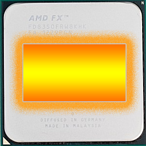
We can already see from the above scheme that the size difference between the heatspreader and the direct contact surface to the CPU on the surface creates areas that are cooler than the area directly above the Die on the surface. This hotter area is also called a hotspot, because most of the waste heat emits on the surface. The simplified representation used in the following pictures as the worst case should be enough for us at this point, although this area is e.g. could be further differentiated by different load behaviors and the positioning of processor cores, cache or even the integrated graphics. For our purposes, however, an overall area is also sufficient. There, by the way, it is like water, which always and constantly naturally searches for the shortest possible way of the least resistance to the outside. Let's look at the CPU from above:
 |
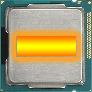 |
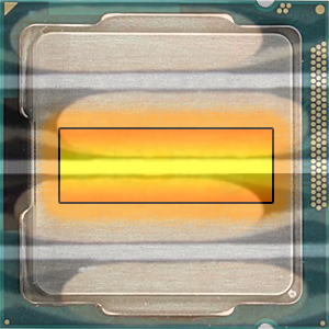
We can see that the Intel CPU has a much narrower hotspot from above due to the smaller structure width! Equipped with this knowledge, one should now also consider exactly how to hit this surface as optimally as possible with a suitable radiator floor (heatsink), then finally, most waste heat must be discharged at exactly this place.
Sense and nonsense of DHT coolers
 CPU coolers with cut heatpipes (DHT, Direct Heat Touch) are (unfortunately) very fashionable and they also save the manufacturer a lot of money in production – which the marketing then sells to the bona fide customer as a super cooling feature. However, this type of construction also poses a certain problem. In the case of a cooler with e.g. only 4 heatpipes can be seen very clearly that CPUs with a very narrow die (e.g. Intel from Ivy Bridge) also have a correspondingly narrower hotspot. However, the two middle heatpipes in the following graphic (Xigmatek Achilles) are not very optimal and can be turned such coolers even in the rarest cases.
And now? If you could turn the cooler by 90°, you could actually live with the problem quite well. AMD users often find it easier, as the coolers are usually facing upwards, so the heatpipes cross the narrow, elongated hotspot and are not aligned along it. For a more up-to-date Intel system or 90° rotated AMD systems, you should only shortlist DHT coolers that have 5 heatpipes and have no (larger) gaps between the cut heatpipes.
You can already lose more of the cooling performance by choosing an inappropriate radiator floor than you could do with the most expensive paste ever! But it's almost worse. Next, let's look at what exactly happens between heatspreader and heat sink.
Huckel pistes instead of smooth surfaces
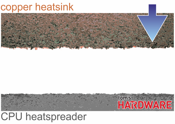
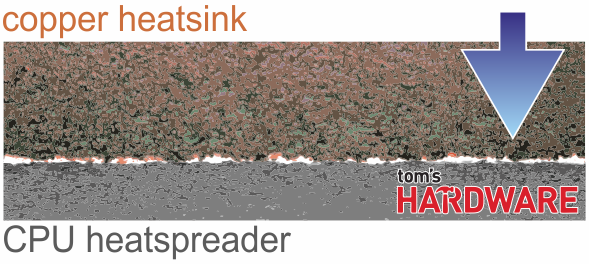
No, so the surfaces of the heat spreader and the heat sink are really not homogeneous. Under the microscope you can see very clearly that a surface that seems smooth to the human eye represents a true huckel piste (Fig. 1)
 |
 |
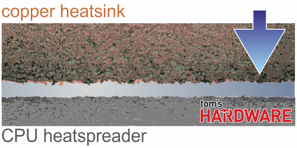
If you press both surfaces together (Fig. 2), it becomes clear that only a few molecules really touch directly and a lot of air is trapped in between. Air, however, is a very bad heat conductor, but rather an insulator. Thus, the entire construction effort fizzles out quite completely, because only where both metal bodies really touch each other directly, the waste heat can also be discharged into the cooler.
A heat-conducting medium must be produced! Paste or pad
This is precisely where the idea of creating an optimal connection between the two surfaces, which is liquid and/or flexible enough, is now the starting point to displace the air outwards and completely replace it. Since such media, whether as a paste, pad or "liquid metal," will never achieve the thermal conductivity of the other two surfaces, the layer must be thin enough to produce as little additional resistance as possible, but still thick enough to cause bumps and thus avoid possible air inclusions.
- 1 - Einführung und Übersicht
- 2 - Grundlagen: Heatspreader und Heatsink
- 3 - Wärmeleitpaste: Funktion und richtiges Auftragen
- 4 - Sonderfall Grafikkarte
- 5 - Sonderfall Wärmeitpads und mögliche Verbesserungen
- 6 - Flüssigmetall und die Grenzen
- 7 - Testsetup und Messmethoden
- 8 - Testergebnisse: Wasserkühlung
- 9 - Testergebisse: Lüftkühlung (großer Turmkühler)
- 10 - Testergebisse: Lüftkühlung (Boxed-Kühler)
- 11 - Testergebisse: Grafikkarten-Kühlung (GPU)
- 12 - Testergebnisse: Viskosität
- 13 - Testergebnisse: Verarbeitung und Anwendungssicherheit
- 14 - Zusammenfassung und Fazit


Kommentieren