


Nothing is better than even more pixels
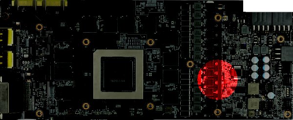
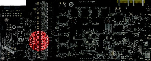
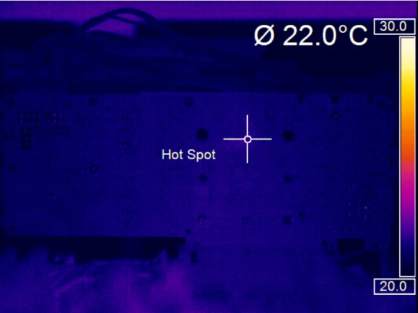
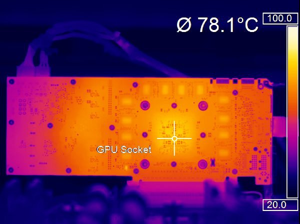
If you consider how high (or rather low) the resolution of conventional infrared cameras actually is and how large the area to be monitored is, including many, often very tiny details (e.g. pins), then you will very quickly understand that many measurements cannot be accurate at all – even if you believe in good faith that they are. Let’s therefore first take a look at the front and back of a graphics card board in different resolutions as an example:
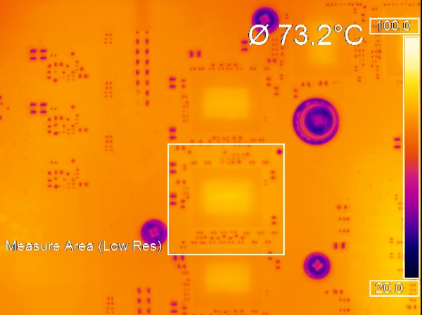
Unfortunately, with low-resolution cameras, you can’t get as close to the object you’re measuring as you’d like to in order to still capture certain details better. Here very hard physical limits are set by the respective optics. We use distances between 20 and 150 cm for our measurements, depending on the object to be measured, the level of detail and the lens. Even with cameras that only offer 320p resolution, you can still get reasonably accurate measurements as long as the optics and distance are right. The rectangle shows the captured area for which such a camera still calculates and outputs a useful average value.
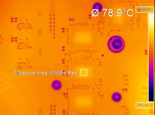
At much lower resolutions, however, it becomes critical. If you want to capture the entire board, you will unintentionally capture much colder areas (pins and lands with noticeably lower emissivity), so the average temperature output will always be significantly too low.
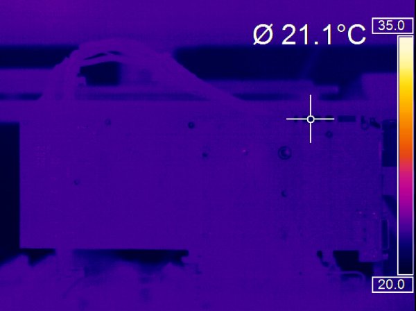
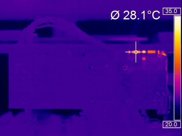
In a direct comparison between a handheld with an image the size of a postage stamp and the high-resolution camera, there can easily be a difference in measurement of up to 10°C, despite the emissivity specification for the VRM, if you don’t have a really sure hand. I have described often enough how such an infrared camera works and how the built-in matrix reacts to thermal radiation. So we’ll save that part at this point. However, we would like to remind you that even many of the better infrared thermometers are absolutely useless for our measurements due to the resolution (diameter of the measuring range), since only an average value for the entire surface is determined and so many details are simply lost:
s
We will come to the problems with the different emissivities of the various surfaces – and how we protect ourselves from errors in concrete cases – on the next page. First, however, we want to address general errors that can be seen again and again in measurements and that can lead to very inaccurate or unusable results.
We see ourselves: Mirroring
Handhelds are incredibly convenient, portable and easy to use – but there is always the user’s body behind the meter! Many surfaces “mirror”, i.e. reflect, the incident heat radiation – and thus we can virtually measure ourselves.
Certain surfaces – especially metals – are incredibly reflective, even if they have been coated with paint. As the thickness of the coating decreases, it quickly reaches a transmittance high enough to cause such distortions.
The room temperature: We first calibrate ourselves
Not only the camera has to be “looked over” from time to time, but also the daily environment has to be right! In order to achieve comparable results, we work with a fixed room temperature of 22°C. This means that, depending on the season and the benchmark process, we even have to keep this value as constant as possible by heating or cooling the room several times.
In addition to measuring the switched-off system at the start of our measurements, we also use a matt-black painted copper box as a second reference in the further course, which is located close to the test system.
From slant to slant brings muck
As tempting as it may be to quickly “shine a light” somewhere – the values obtained in this way are usually much too low! You will not be able to avoid unscrewing an object yourself or – if this is not feasible – it is better to do without this type of inaccurate evaluation altogether. The following example with two different angles (perpendicular at 90° and acute at approx. 30°) shows what we mean by this:
Despite painting with our special paint, which we will come back to in a moment, the values are simply no longer correct if the angles are too acute:
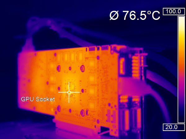
Apart from the fact that we cannot increase the “depth of field” with aperture tricks as we are used to from a normal camera, the abstraction of heat is not the same (strong) in all directions. At below 15° we then get only absolute binary decay. Now let’s move on to our “poison cabinet”, where we keep a few little secrets as well as a very expensive liquid that will help us rule out any further measurement inaccuracies.


Kommentieren