


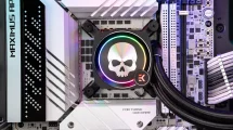
Just three days after these steps, the control board arrived and it was time to assemble it:
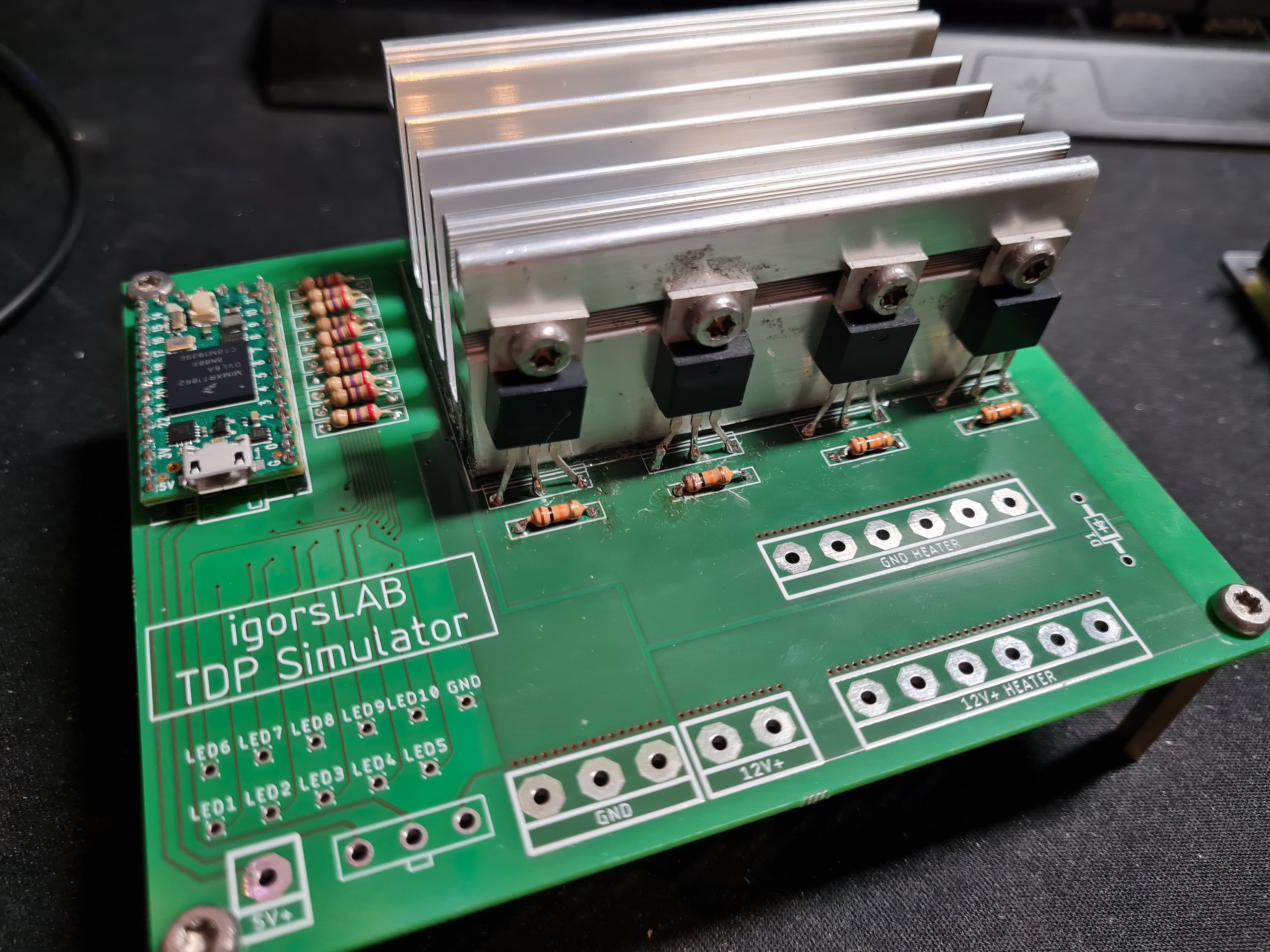
On the left rear side we see the microcontroller with the series resistors for the LED display of the power stage. Next to them are the four MOSFETs, which were mounted to the heatsink with thermal paste. In front of it the resistors for discharging the gates are enthroned. Not yet soldered and connected are the wires for the display LEDs, the supply and return lines for the heater core, and the connections to the potentiometer for power level selection.
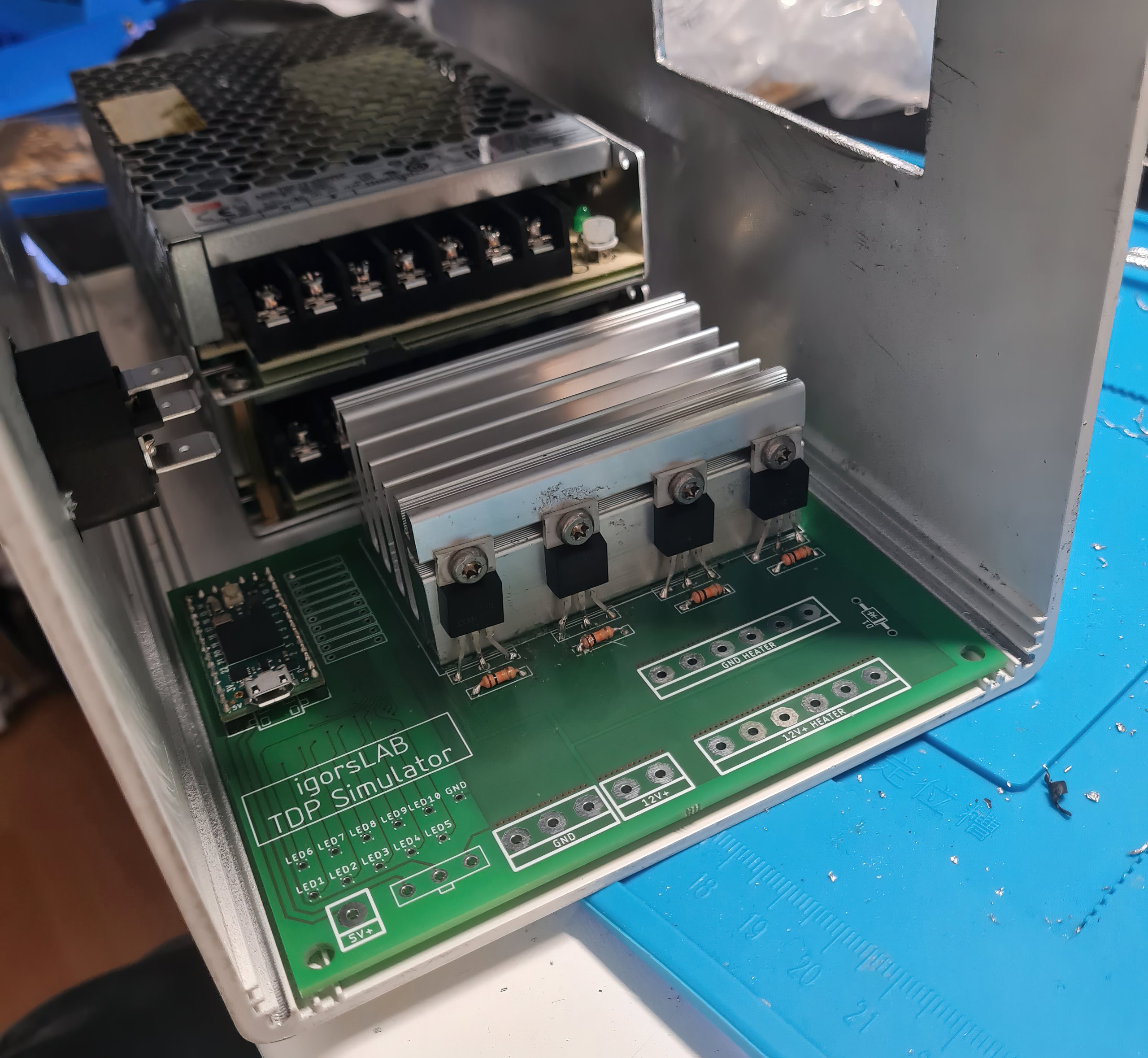
Installed in the housing it looks like this:
When everything was wired so far, it went to the creation of the heater core support. This should be made of copper or aluminum. Since it was difficult for me to get solid material in copper, I decided to use aluminium. The support was provided with a hole for the temperature sensor and cut so that it has the minimum height and fits exactly on the PCB of the heater core. The contact surfaces were then polished to ensure optimum heat transfer. From the hardware point of view, the last thing to do was to fit the measurement displays. A large display shows the set power level in voltage, current, power and time. A small display shows the temperatures in the power amplifier and in the heater core, so that all temperature-critical subsystems can be monitored at all times.


33 Antworten
Kommentar
Lade neue Kommentare
Urgestein
Urgestein
1
Urgestein
Urgestein
Urgestein
1
Veteran
1
Veteran
Urgestein
Mitglied
Mitglied
Mitglied
Urgestein
Urgestein
Urgestein
Mitglied
Alle Kommentare lesen unter igor´sLAB Community →