


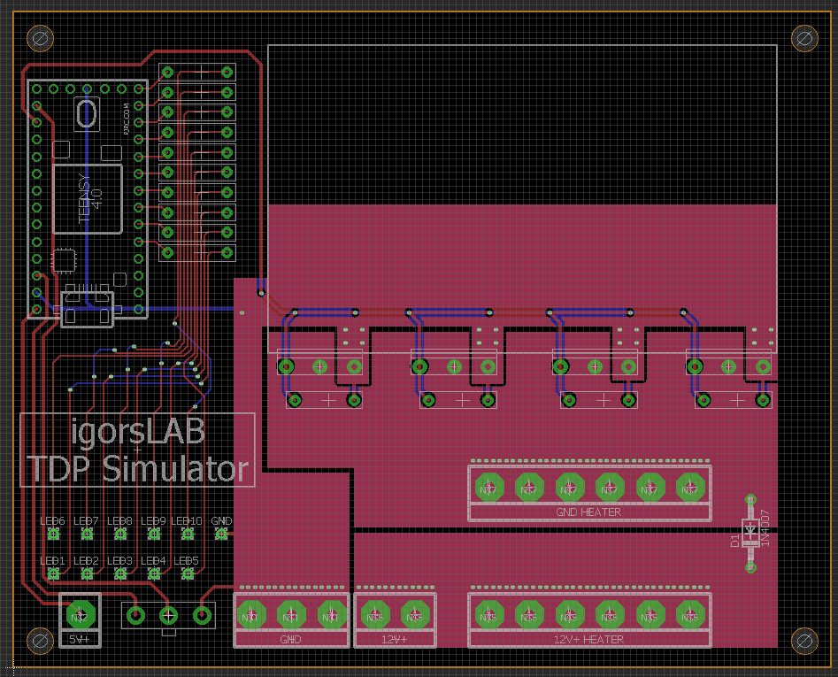
A microcontroller is to be used to control the heater core via PWM and to visualize the operating states via LEDs. My choice was an ARM Cortex M7. This microcontroller allows me to set the PWM frequency of each pin, an ATMEGA 328 can only do that via grouped timers, which would cut me down on calibration. So the brain was selected, what is missing is the construction of the output stage, which in the last consequence then separates the ground from the resistors in the duty cycle of the PWM signal and thus regulates the power.
I chose N-Channel Enrichment MOSFETs with Logic Level Gate, which in turn are mounted on a sufficiently large heat sink. Of course, MOSFETs don’t generate incredibly high heat when switching, especially if they are operated within the so-called saturation, but after all we should switch some amps and not just a small LED. In order for the MOSFETs to open the circuit, we still need a discharge resistor per MOSFET gate to discharge the gate charge to ground so that when the signal at the gate is low, it becomes non-conducting.
Since caution is the mother of china, I also provided a free-wheeling diode. We may need these as we are disconnecting the ground from the circuit rather than say 12V+. If the switched load behind the MOSFETs becomes more resistive than expected, this freewheeling diode provides a little thermal relaxation of the MOSFETs and in the best case even prevents destruction by feedback from the resistors. After this small but fine two-layer PCB was designed, it looked like this and could be manufactured:
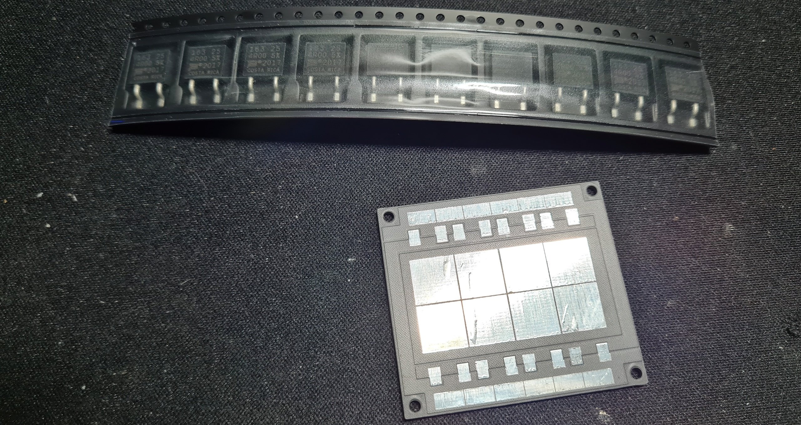
In the meantime the heater core PCB and the resistors arrived:
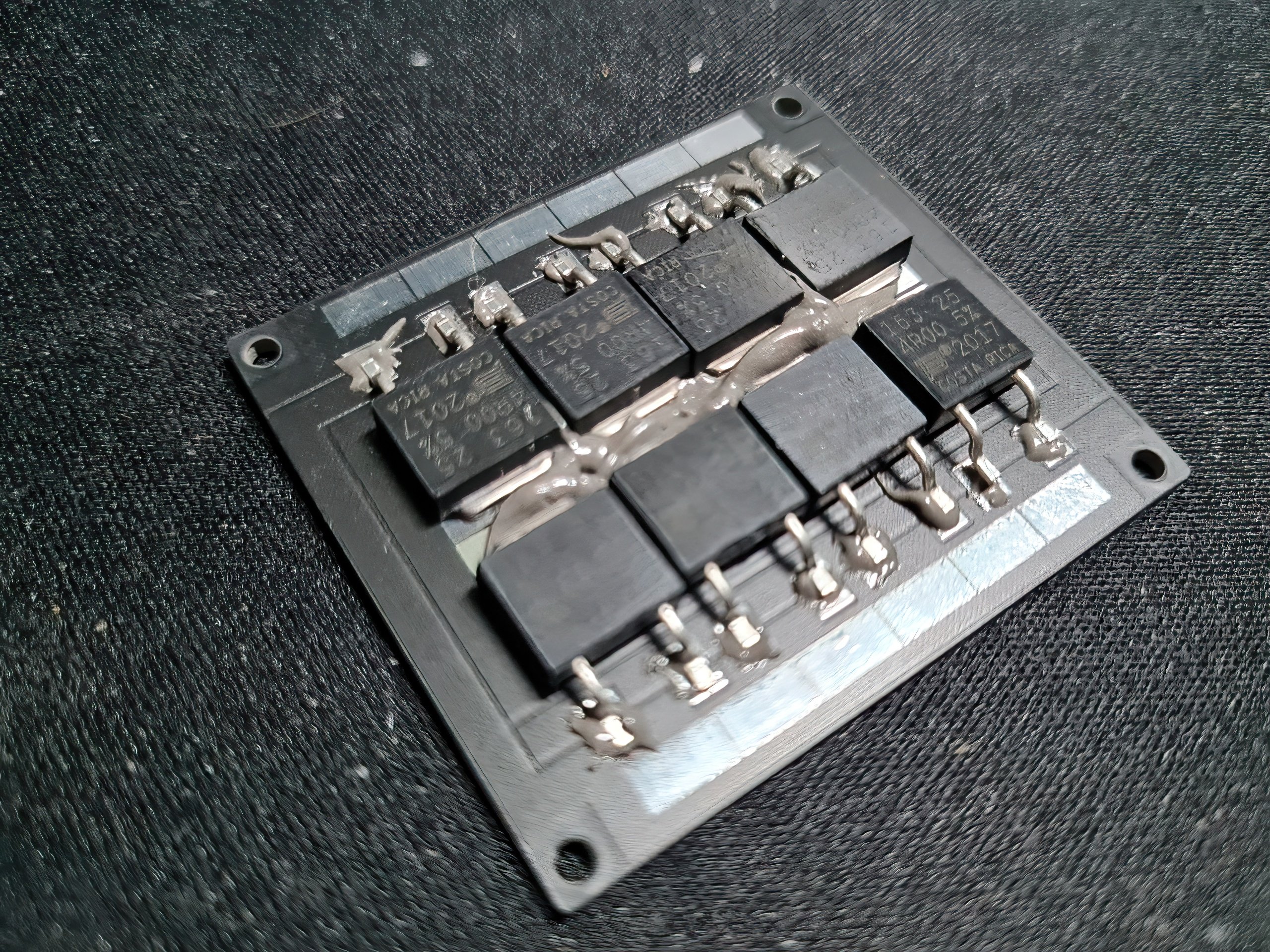
After applying the SMD solder paste it looked like this:
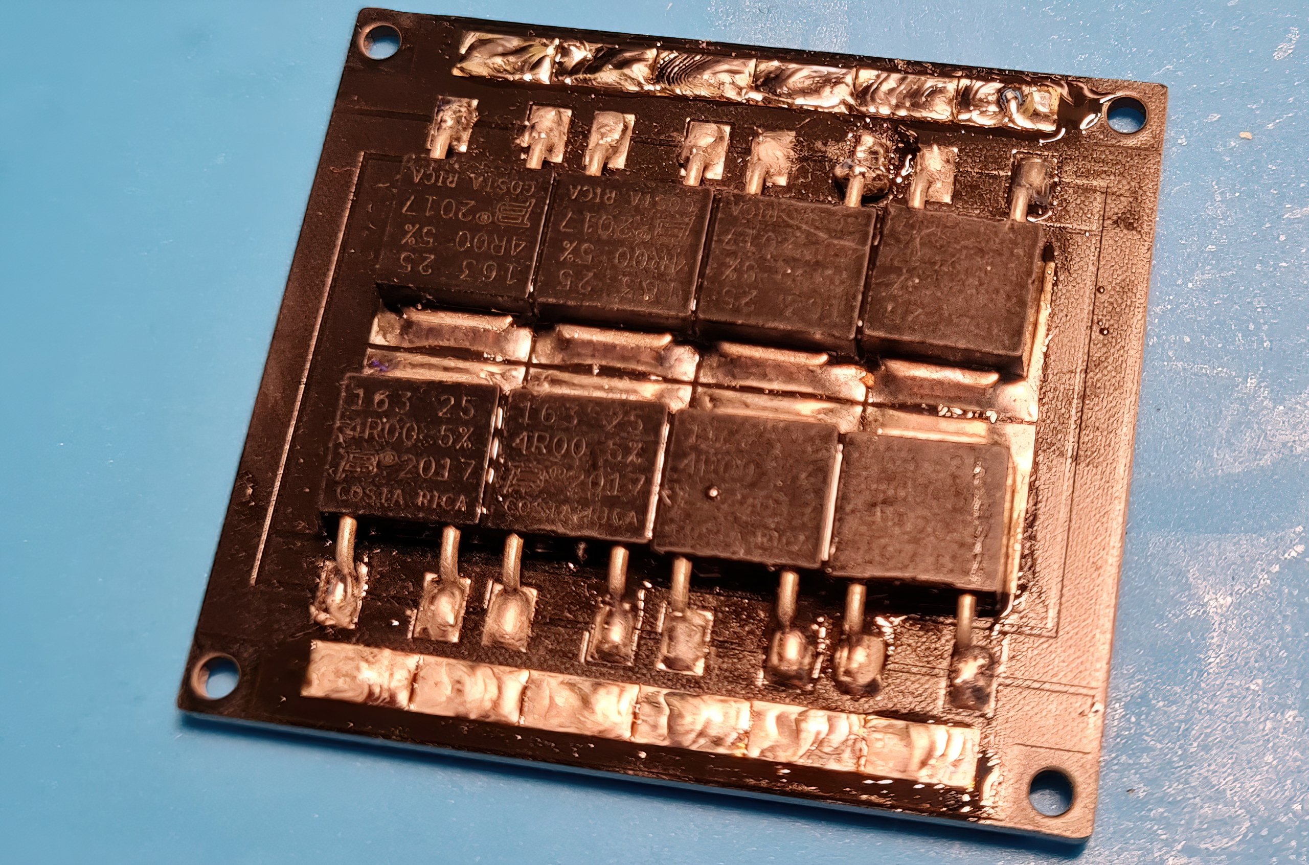
Finished soldered (but not yet reworked) the heater core showed up like this:


33 Antworten
Kommentar
Lade neue Kommentare
Urgestein
Urgestein
1
Urgestein
Urgestein
Urgestein
1
Veteran
1
Veteran
Urgestein
Mitglied
Mitglied
Mitglied
Urgestein
Urgestein
Urgestein
Mitglied
Alle Kommentare lesen unter igor´sLAB Community →