


Unfortunately, the case is completely different for AMD, so I have to elaborate a bit more. AMD only allows the evaluation of the so-called TGP (Total Graphics Power) via software. This value is the sum of GPU (VDDC_GFX), memory (MVDD), memory controller (VDDCI) and SoC (VDD_SOC). The memory controller is a bit tricky with AMD. AMD still had two sources on the Radeon VII, namely VDDRC for the HBM and VDDCI, and only MVDD and VDDCI on the Vega cards and Navi. VDDCI, by the way, is plenty special, but not a big item performance-wise, although important.
AMD uses this voltage for the GPU-internal level transition between the GPU and the memory signal, so it is something like the voltage between the memory and the GPU core on the I/O bus. And where does the memory controller hang on AMD then? On both! The controller gets the supply from both sources, which cannot be separated cleanly in this case. However, since the memory controller is considered part of the GPU, its inclusion in the TGP is only logical.
The scheme for the TGP-relevant areas shows that apart from the GPU and the memory, NOTHING else is really included. AMD’s specifications thus refer purely to the GPU and the memory, EXCLUDING all other losses, including those of the voltage converters! This is also reflected in the fact that the power consumption of hot AMD graphics cards can increase significantly without the performance dropping completely.
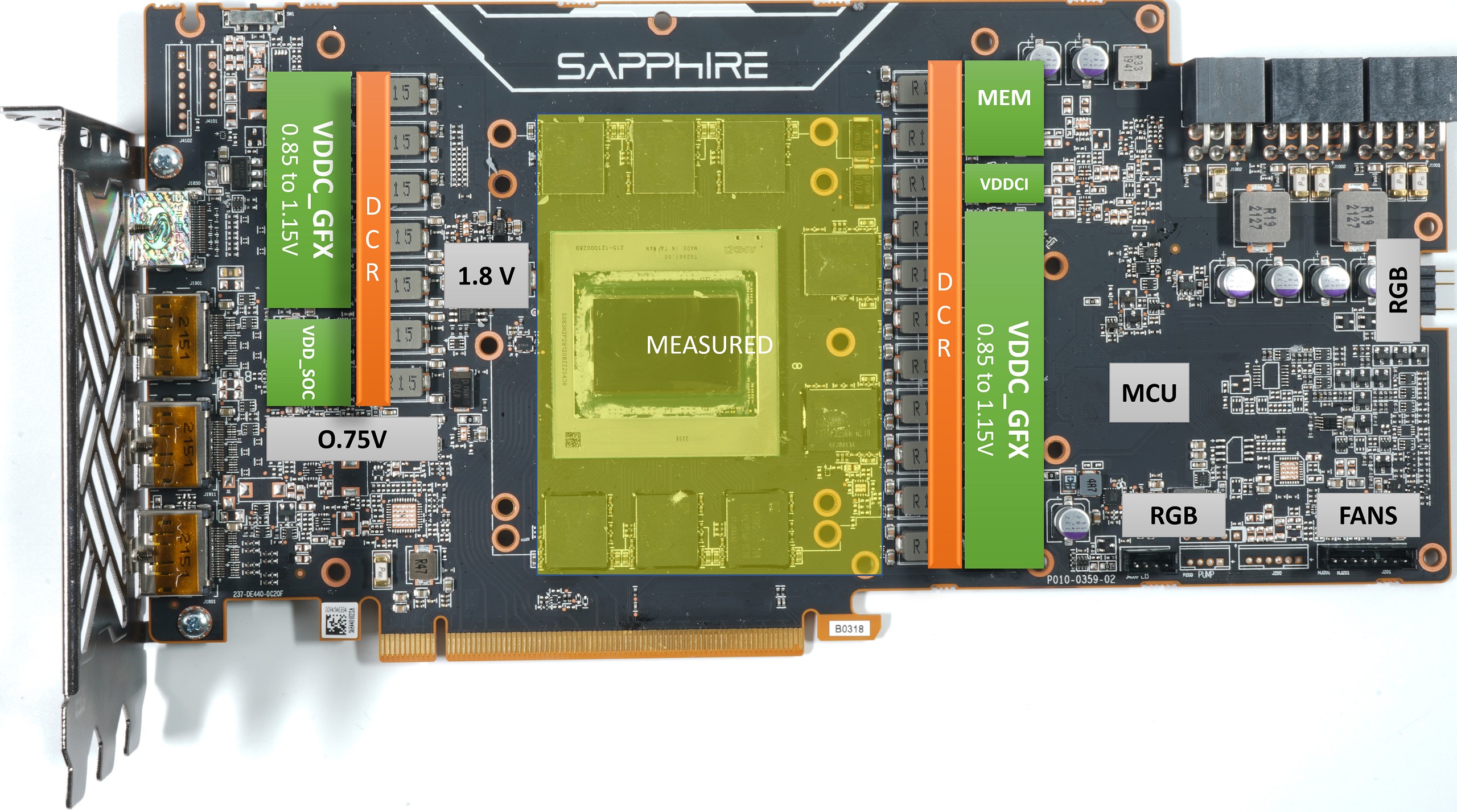
DCR – AMD’s replacement solution for true monitoring of rails
Since there are no shunts and monitoring chips on the AMD cards, the firmware has to get the data differently. For this, one uses data that all graphics cards have. Thus, one simply uses the values of the currents as a substitute, which all relevant voltage transformers supply anyway. This is done at the output of the phases, that is AFTER all the losses that occur. In order to ensure the balance of the phases and to be able to control the individual control loops, a special procedure is required. The buzzword is DCR (Direct Current Resistance). And now we also understand that this only locally collected data is incomplete, because it doesn’t even include the fans, let alone the other installed electronic consumers and board losses.
But how does that DCR work? Each component has very specific characteristics in this respect and to cut a long story short: The DCR is the basis for calculating or measuring temperatures and currents. But how exactly does the controller know which currents are flowing in which control loop? Monitoring can be different, because – what a surprise – there are different methods for it. So I often read something about Smart Power Stages (SPS) and IMON (power). IMON is, after all, exactly what the so-called MOSFET DCR delivers and what we so desperately need!

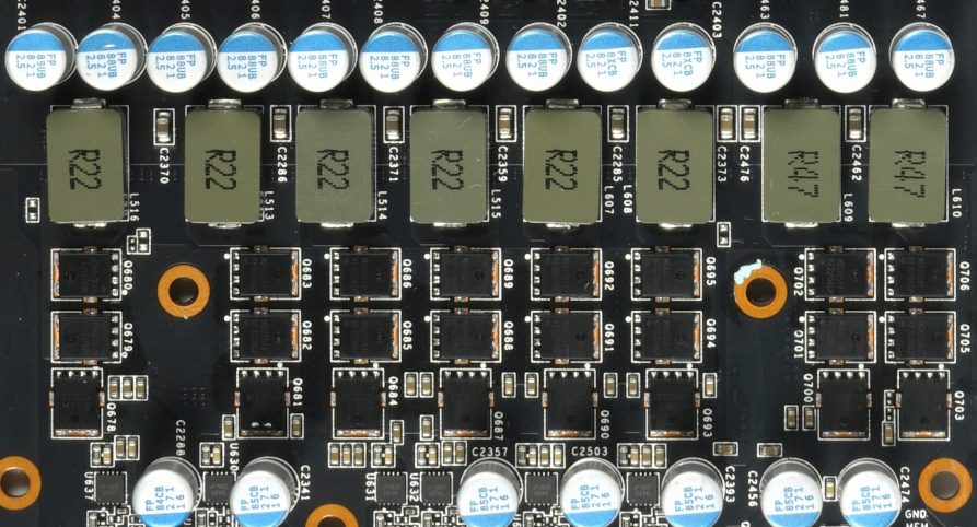
The picture above shows the typical layout with the intelligent PLCs that provide the value for the current for each individual control loop with IMON, which is so urgently needed for perfect balancing, i.e. the balance between the phases. How the PLC determine this value? The drain currents of the MOSFETS are measured in real time and these values are also extremely accurate (5 μA/A signal in the example above). Meanwhile, the more powerful AMD and especially NVIDIA cards use the MOSFET DCR.
This very cost-intensive solution replaces the much less expensive Inductor DCR, i.e. a current measurement via the inductive resistance of the respective filter coils in the output range. AMD and Nvidia, for example, use such a solution for inexpensive cards (symbol image below), where the current flow is a bit more leisurely. However, the accuracy of this solution is significantly lower and is also strongly influenced by variations in component quality. Too large tolerances can therefore quickly tip the entire balance!
The quality of the coils is always a story in itself and it also explains why there are always problems and inaccuracies. AMD has relied on this Inductor DCR for years, but it is no more than a rough estimate and becomes increasingly inaccurate especially at higher temperatures. Only the Radeon VII uses (therefore all the more expensive) PLCs from International Rectifier and thus also fully MOSFET DCR for the important voltage control circuits for the first time. Although all this is only indirectly related to the voltage transformer losses, it helps the controller to optimally control and monitor the phases. This helps to avoid or reduce overloads and hotspots, and in the end, of course, efficiency benefits as well. And, of course, the monitoring software is also pleased because the TGP can be recorded more accurately.
Reading via software is impossible and not plausible
The TGP is sometimes even more than 100 watts below the actual total power consumption of such a card in large graphics cards! Unfortunately, anyone who then takes this from the software at face value is deceiving themselves. Often without even knowing it. And when you read the discussions in the forums about how efficient the respective Radeon is, then I know why I wrote today’s article. I won’t owe you the proof for much longer, once more you have to scroll.


657 Antworten
Kommentar
Lade neue Kommentare
Urgestein
1
Urgestein
Veteran
Mitglied
Veteran
Urgestein
Urgestein
Urgestein
1
Urgestein
1
Urgestein
Urgestein
Urgestein
Urgestein
Veteran
Urgestein
Urgestein
Alle Kommentare lesen unter igor´sLAB Community →