


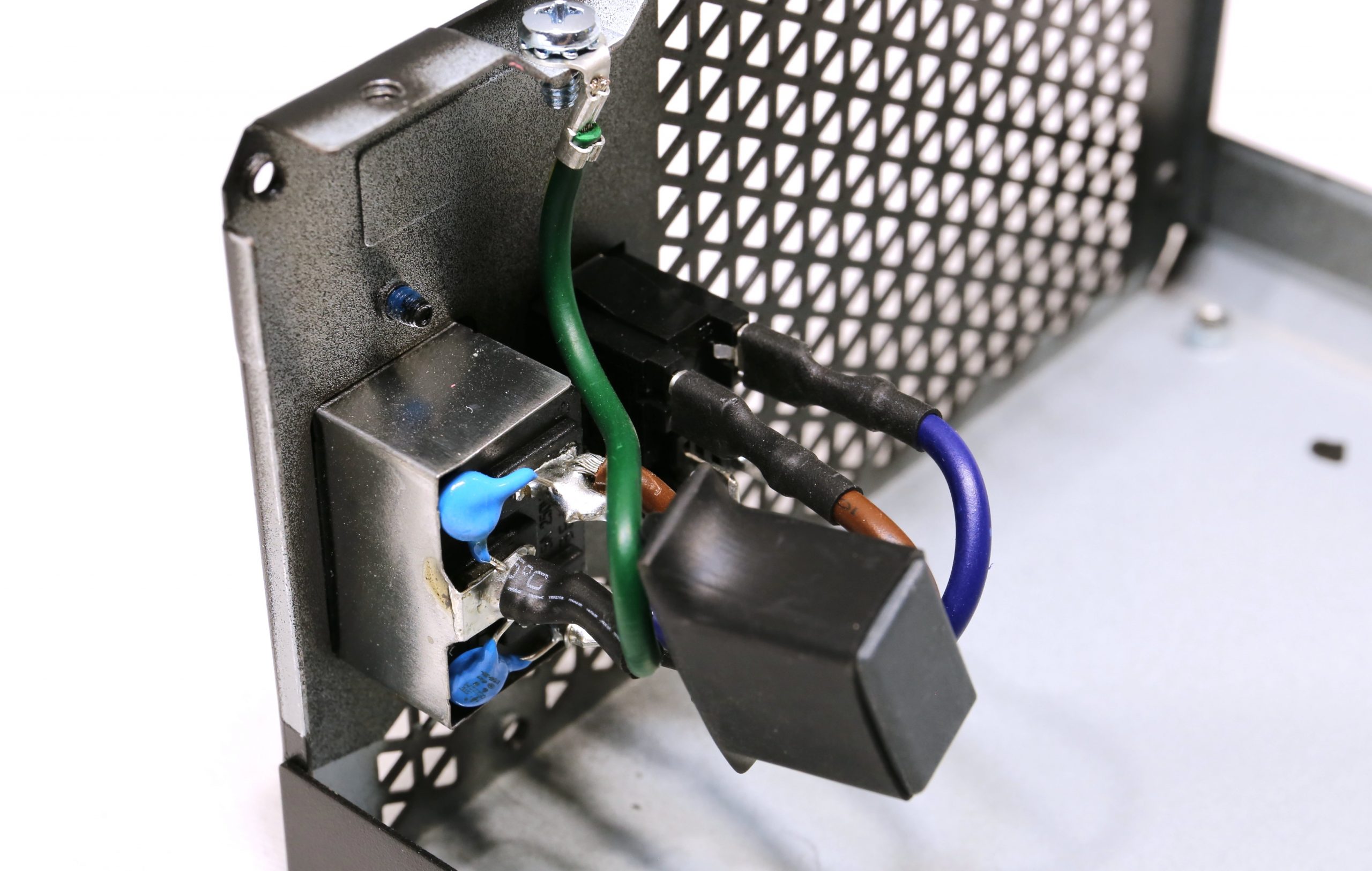
First, we just open the lid. The transient filter is complete and includes everything you need. EMC should therefore not be an issue here in either direction. The picture shows the part located at the rear panel directly at the IEC connector and the switch, the rest is located on the PCB (picture gallery below). All right, the lid’s off…

… so let’s first take a rotating look at the board from above:
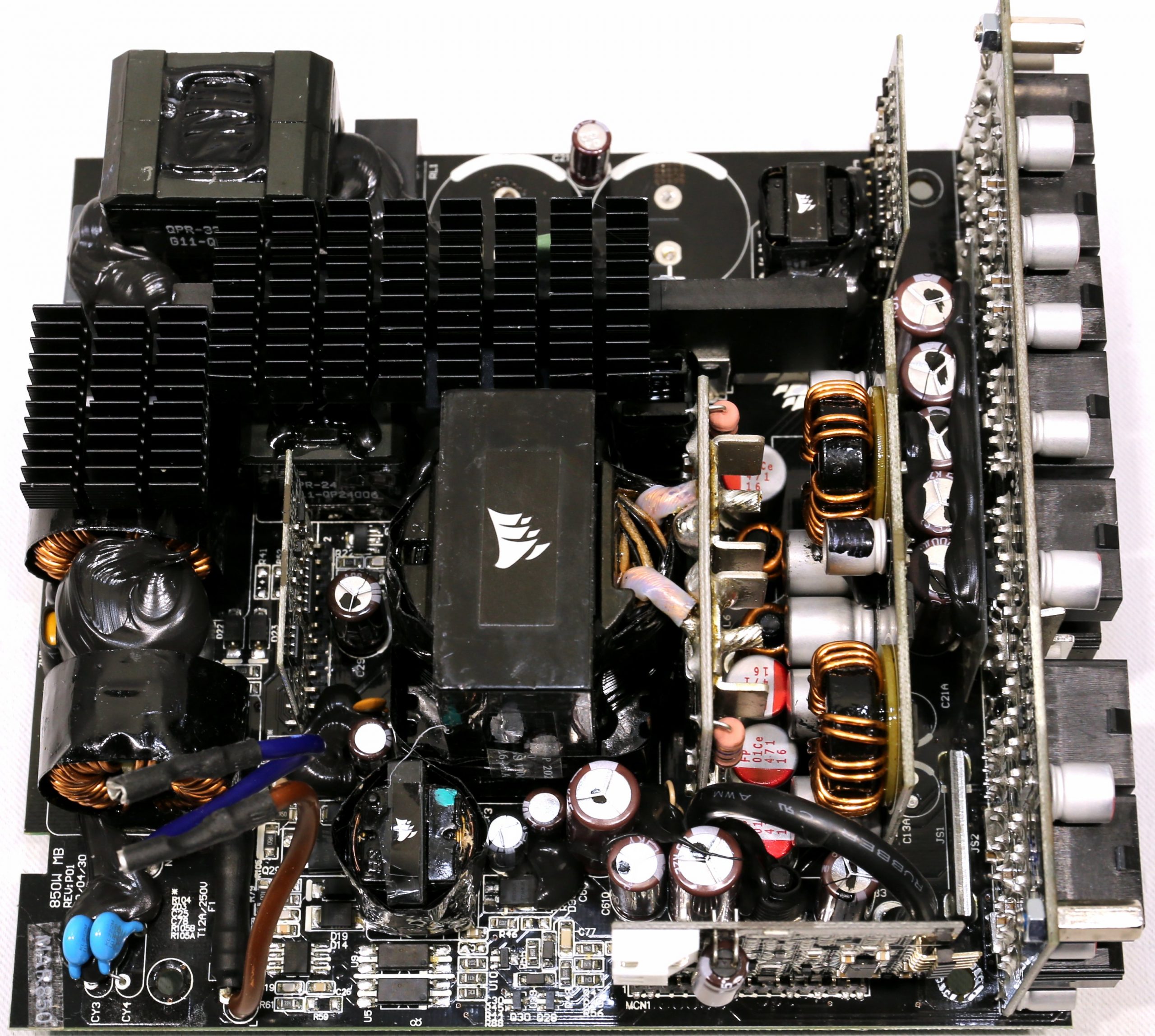
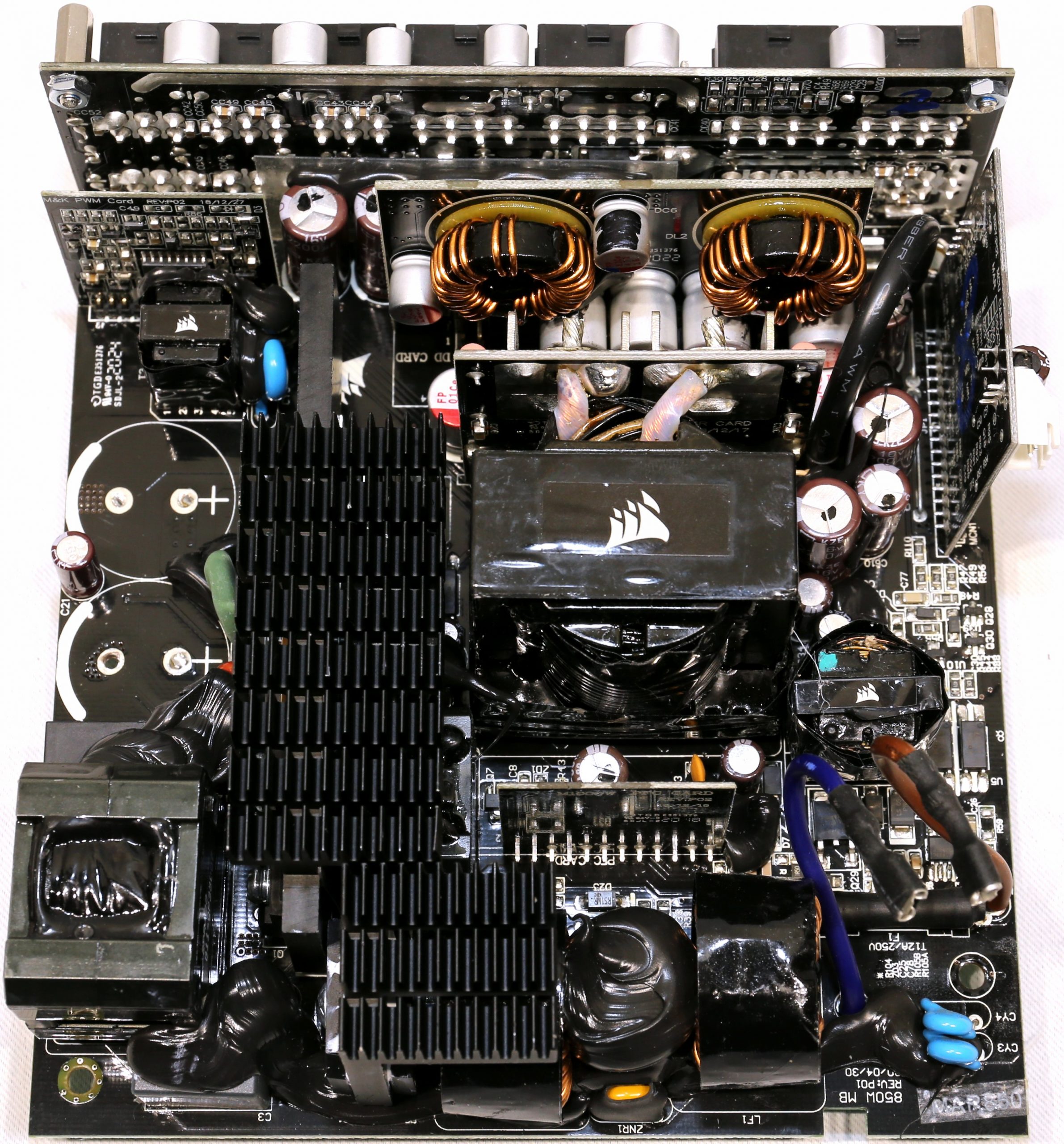
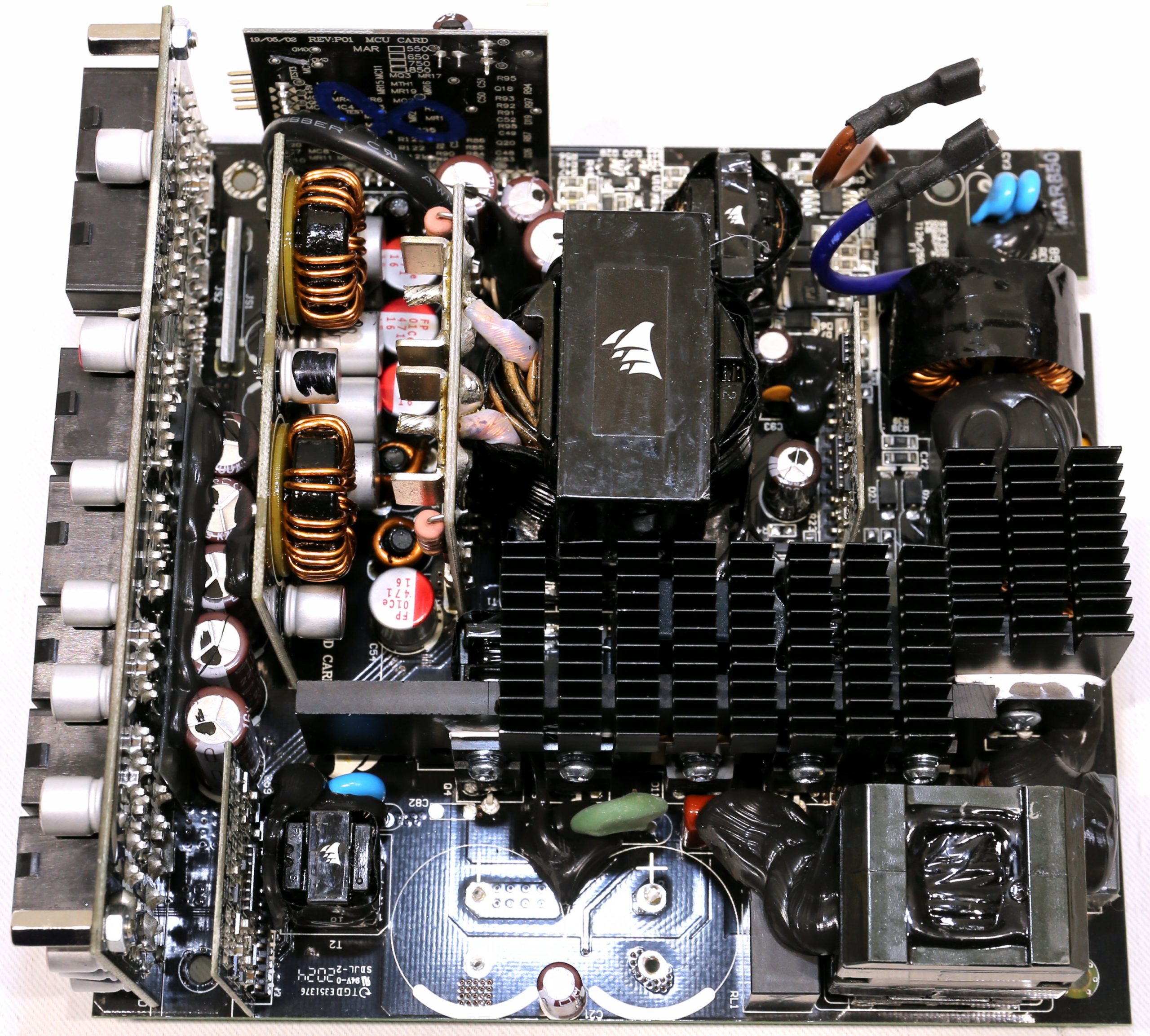
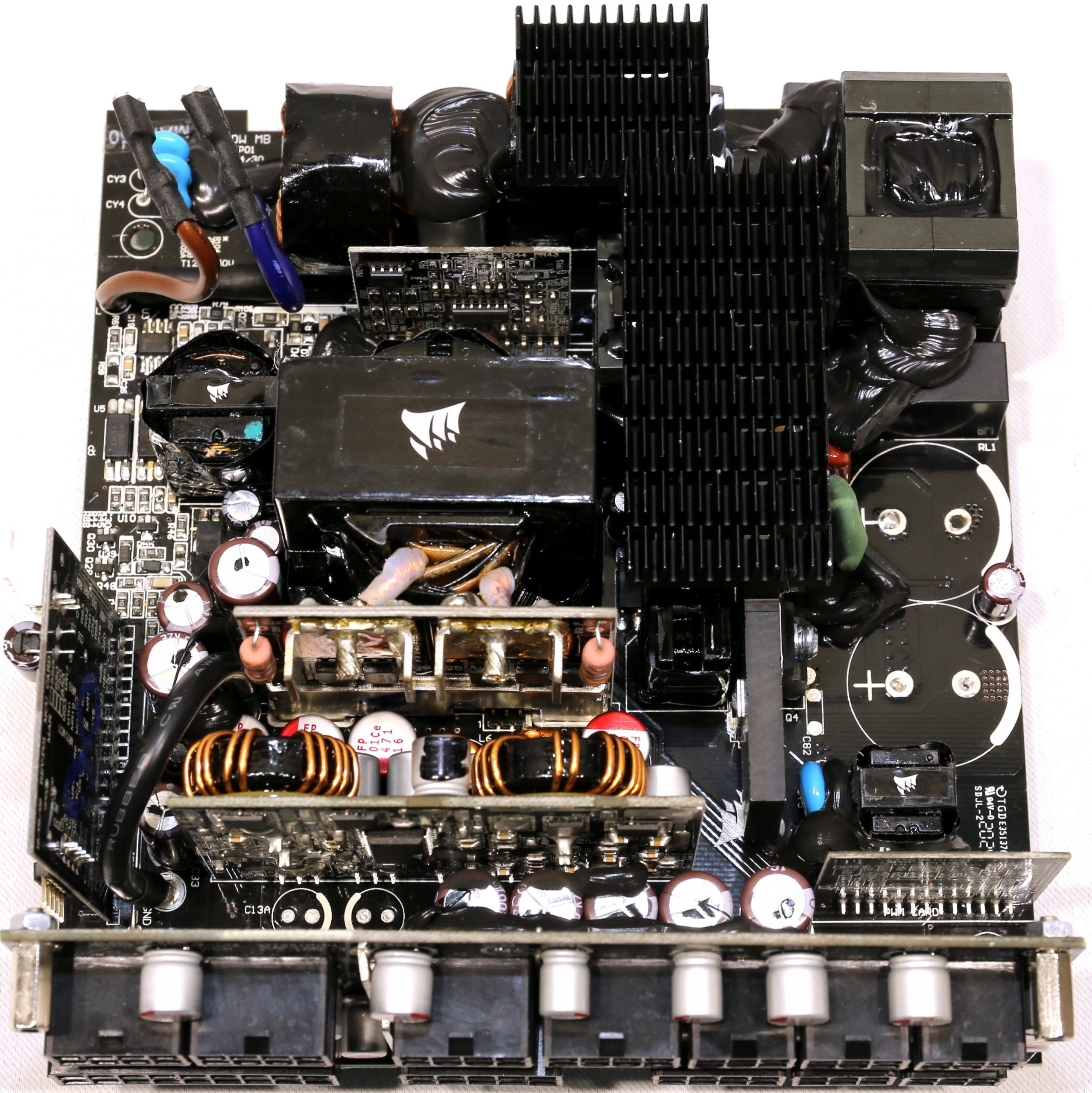
The platform comes from CWT and at first glance it looks just like the older RM850x platform, but there are definitely some interesting differences. The components used by CWT are of high quality. All capacitors are from Japanese manufacturers and a large number of polymer caps are also used. Since the PCB dimensions are regular, there is plenty of space between components so that airflow is not obstructed.
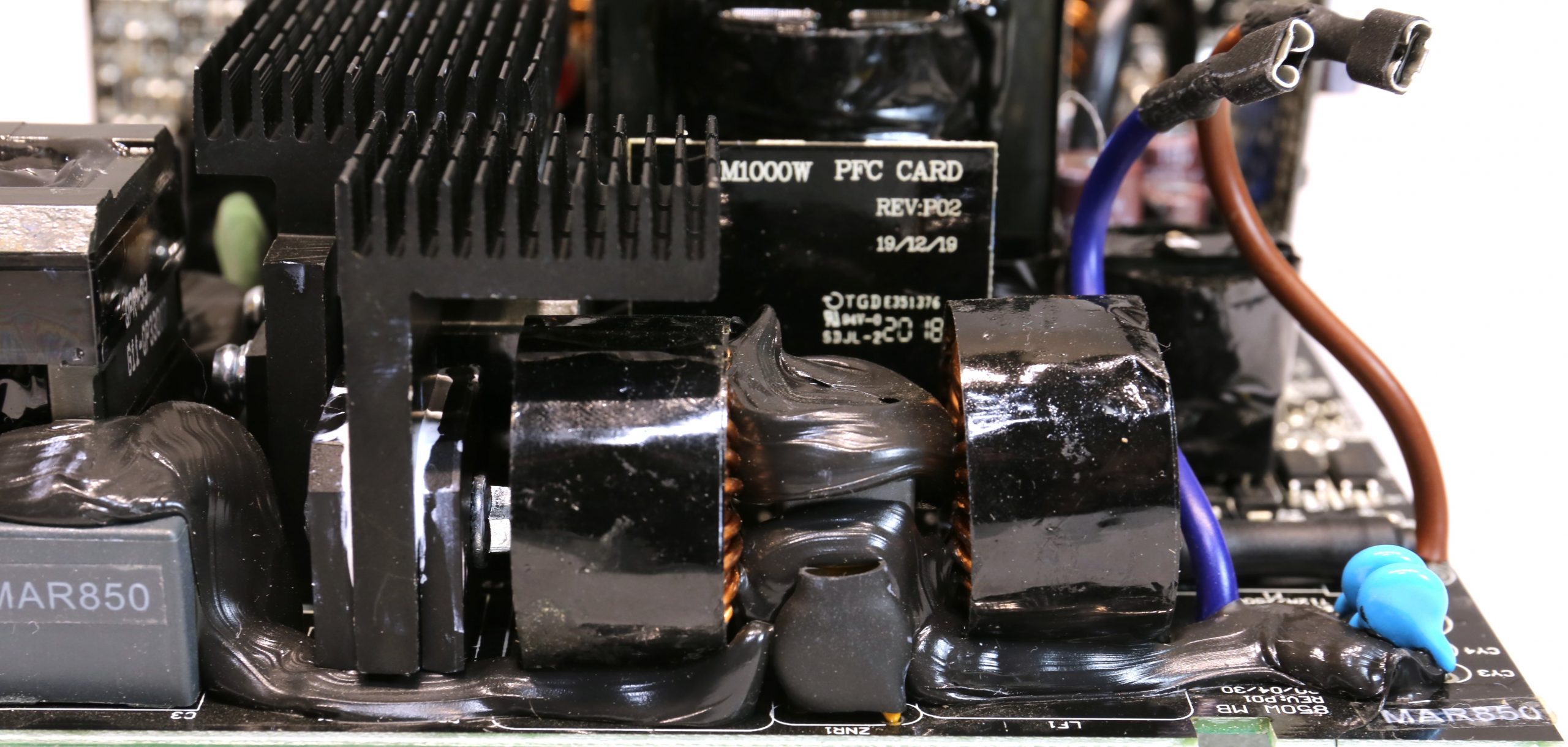
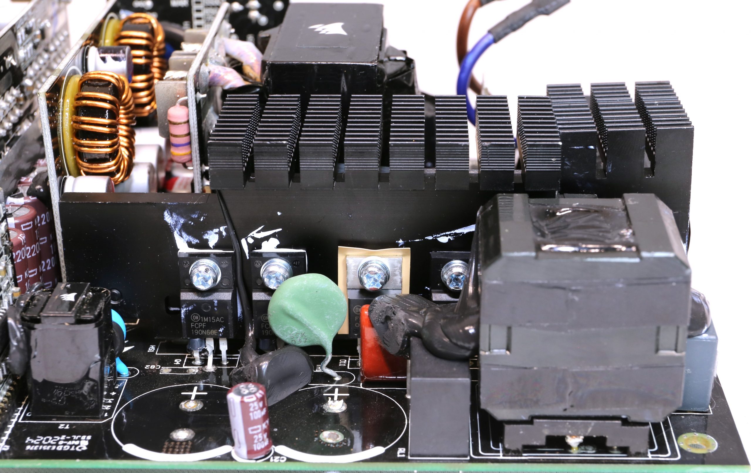
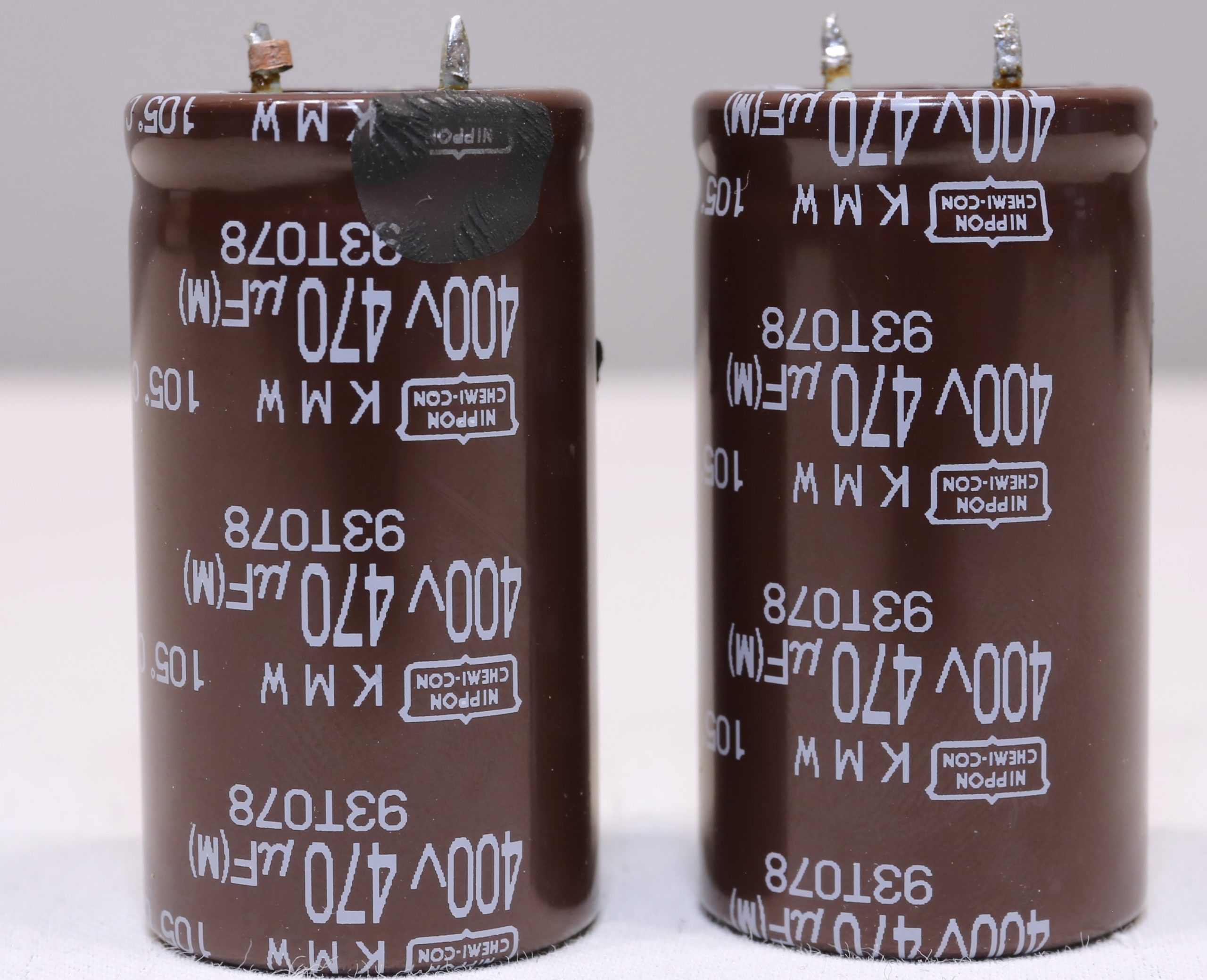
The transient filter has all the necessary components to handle voltage spikes and suppresses incoming and outgoing EMI emissions (we already covered some of the input filtering above). Large inrush currents are suppressed by a combination of the NTC thermistor and a bypass relay, which does a good job. The two well-equipped bridge rectifiers can handle a current of up to 30 A and the FETs of the APFC converter are from Vishay, so they are of best quality. The same goes for the boost diode, which is strong enough for the job. Finally, the bulk caps are from Chemi-Con and have enough capacitance to provide a holdup time of over 17 ms.
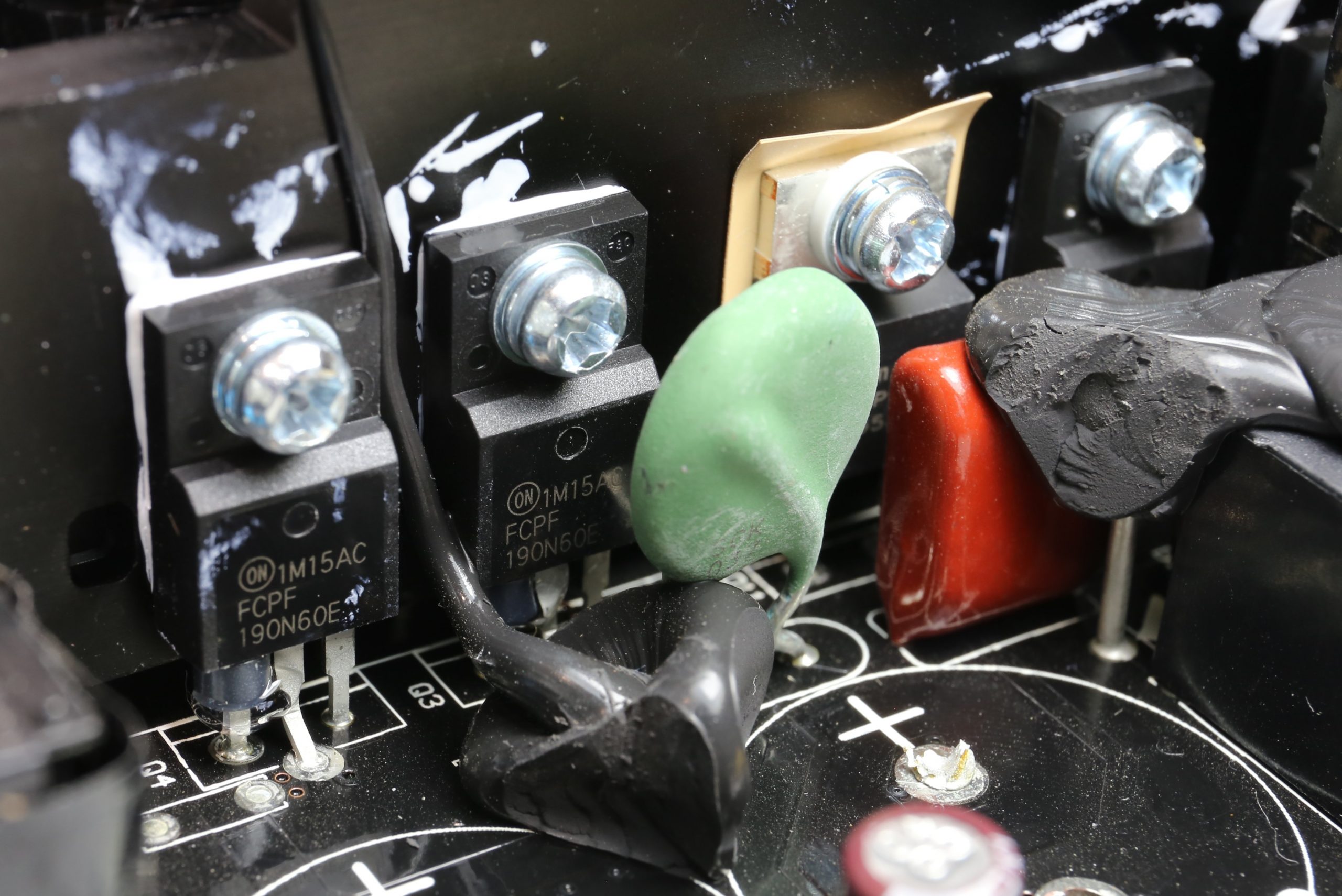
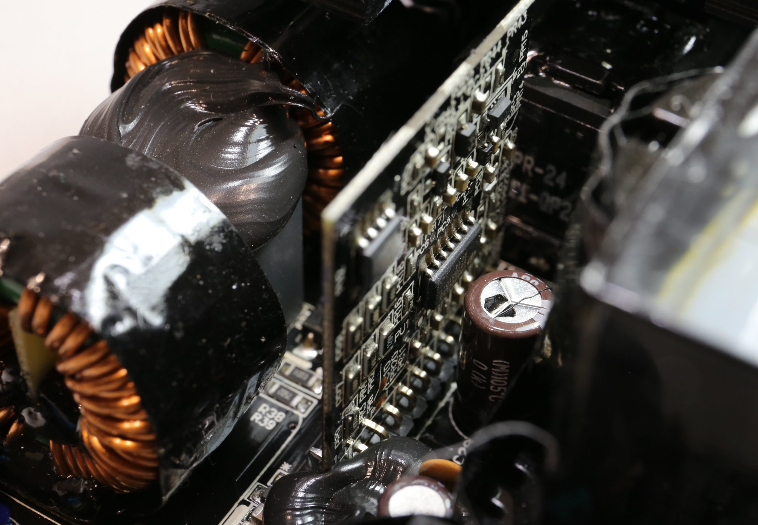
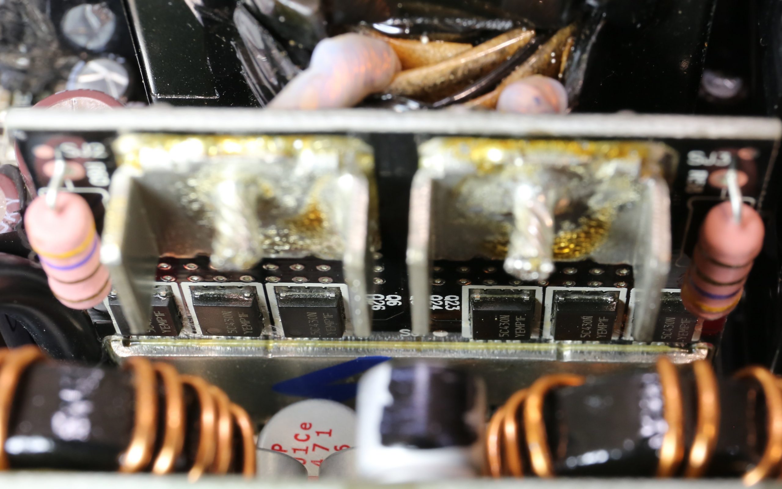
The main FETs are two on-semiconductor FETs installed in a half-bridge topology, the APFC controller is the Champion CM6500UNX and a CM03X IC supports it. The LLC resonant regulator is a Champion CU6901VAC. The FETs that regulate the +12 V rail are six On Semiconductor NTMFS5C430Ns. They are installed on a vertical board near the main transformer. Two DC-DC converters generate the shunts. They use four UBIQ FETs, and the common PWM controller is a UPI Semi uP3861P.
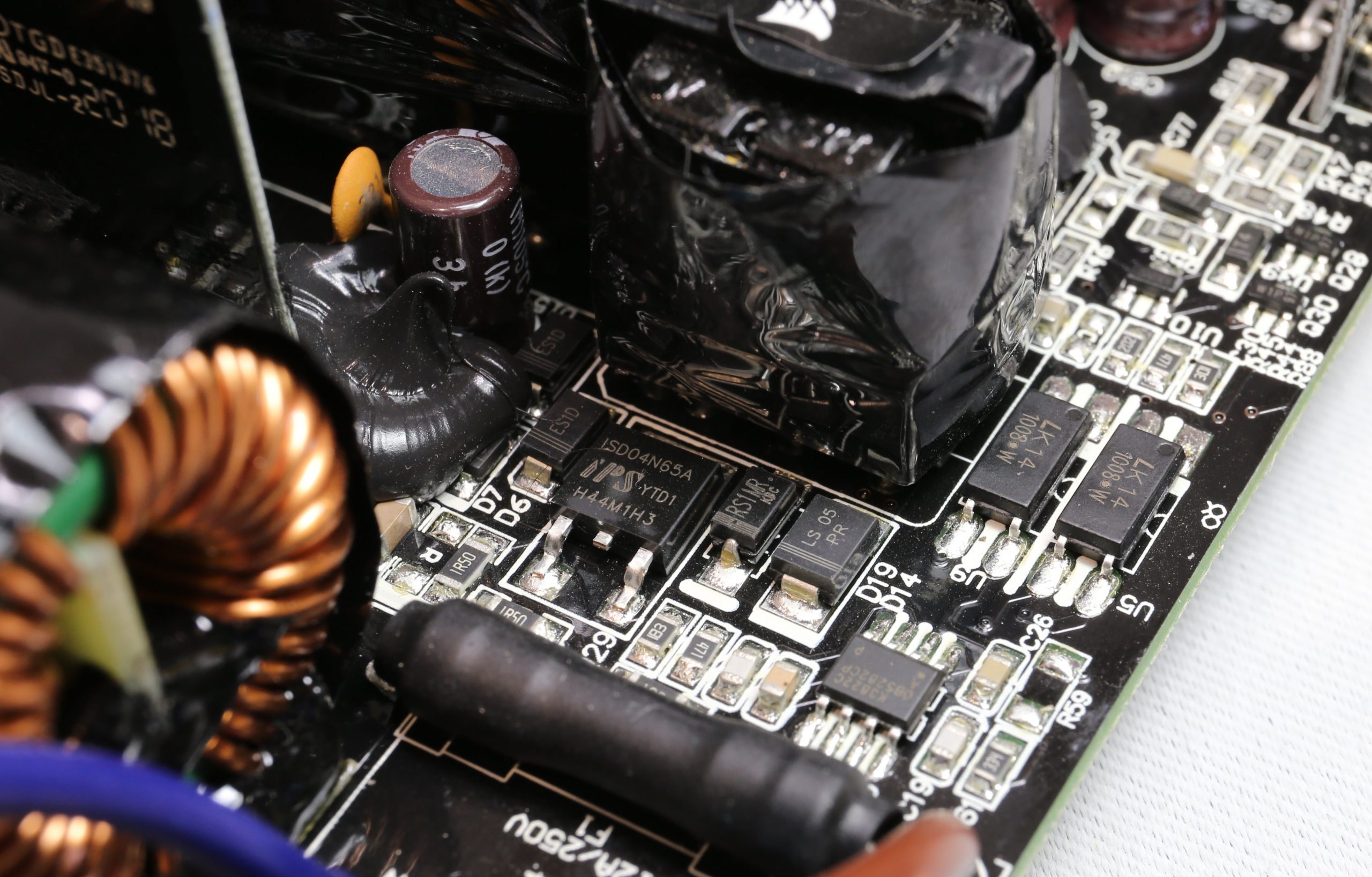
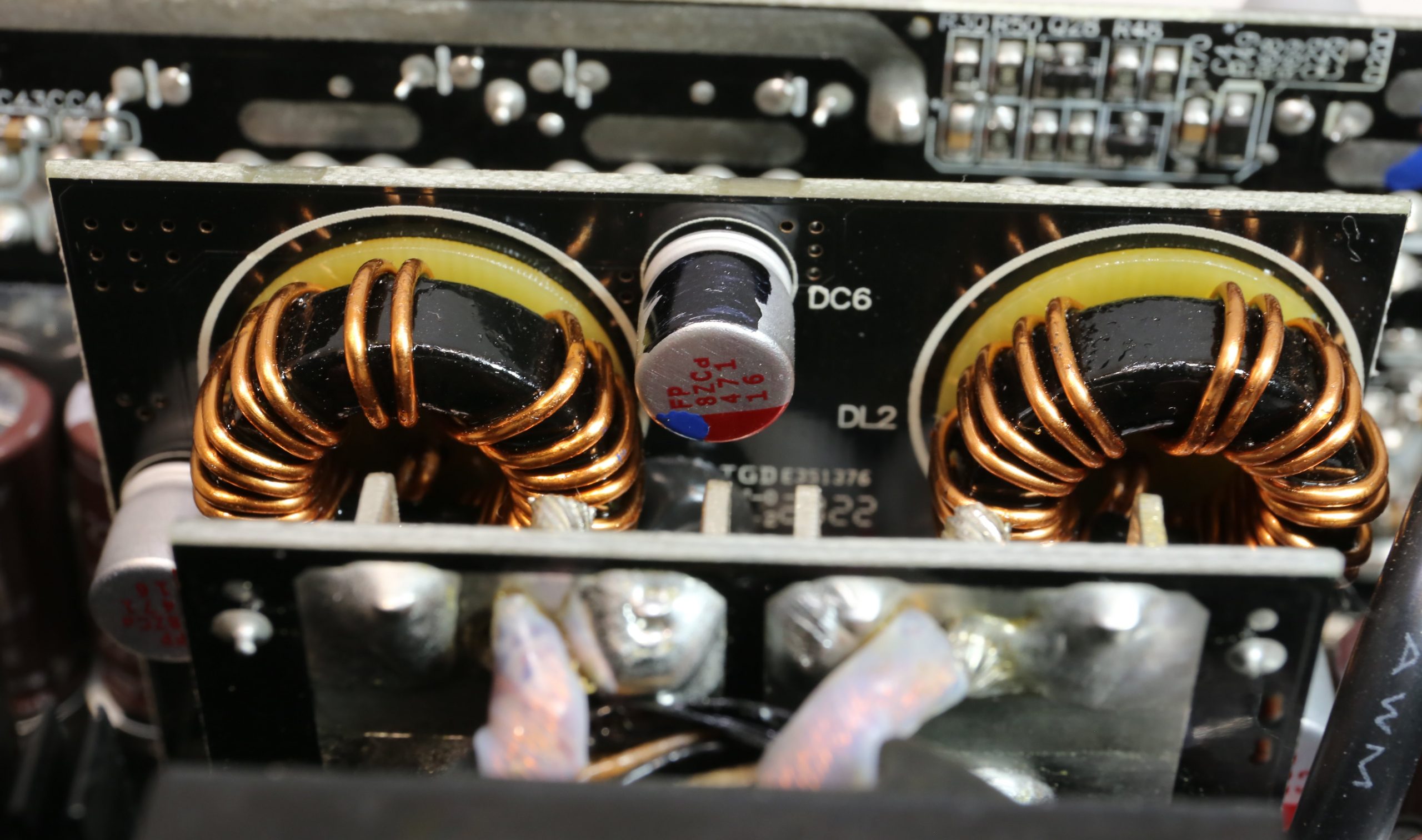
The electrolytic capacitors are from Chemi-Con and Rubycon, and there are plenty of polymer capacitors from FPCAP that are much more tolerant of high operating temperatures. The 5VSB circuit uses a PS1045L SBR on the secondary side, and the standby PWM controller is an on-bright OB5282 IC. As soon as the power supply starts, the 5VSB rail takes power from the 5 V rail. This is done via a changeover switch, a Sync Power SPN3006 FET.
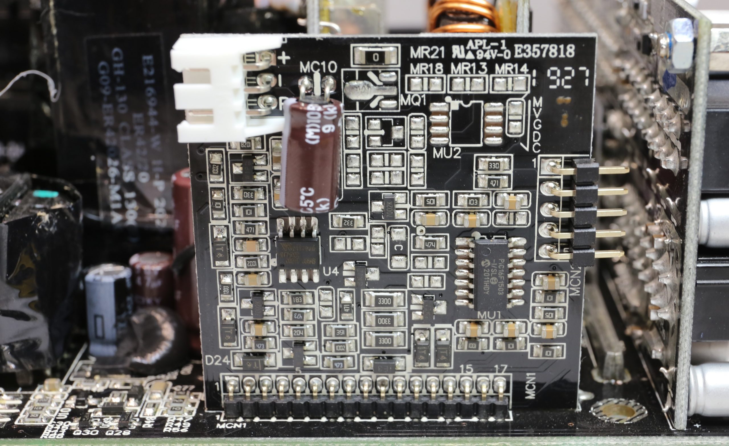
An additional board contains the supervisor IC and the fan controller with a PIC16F1503 IC, which enables precise speed control. The quality of the soldering is good, but the surface of the board could be better. The following gallery shows the just mentioned components and assemblies in detail:
Also at this point, of course, we have Aris’ table again with all the components and data:
| Manufacturer (OEM) | CWT |
|---|---|
| PCB Type | Double-sided |
| Primary side | |
| Transient Filter | 4x Y caps, 2x X caps, 2x CM chokes, 1x MOV |
| Bridge Rectifier(s) | 2x GBU1506 (600 V, 15 A @ 100 °C) |
| Inrush Current Protection | NTC Thermistor (SCK-037) (3 ohm) & Relay |
| APFC MOSFETs | 2x Vishay SiHF30N60E(650 V, 18 A @ 100 °C, Rds (on): 0.125 ohm) |
| APFC Boost Diode | 1x STMicroelectronics FFSP0865A (650 V, 8 A @ 155 °C) |
| Bulk Cap(s) | 2x Nippon Chemi-Con (400 V, 470 uF each or 940 uF combined, 2,000 h @ 105 °C KMW) |
| Main Switchers | 2x On Semiconductor FCPF190N60E (600 V, 13.1 A @ 100 °C, Rds (on): 0.19 ohm) |
| APFC Controller | Champion CM6500UNX & Champion CM03X |
| Switching Controller | Champion CU6901VAC |
| Topology | Primary side: APFC, half-bridge & LLC converte r Secondary side: synchronous rectification & DC-DC converters |
| Secondary side | |
| +12 V MOSFETs | 6x On Semiconductor NTMFS5C430N (40 V, 131 A @ 100 °C, Rds (on): 1.7 mOhm) |
| +5 V & +3.3 V | DC-DC Converters : 2x UBIQ QM3054M6 (30 V, 61 A @ 100 °C, Rds (on): 4.8 mOhm) 2x UBIQ QN3107M6N (30 V, 70 A @ 100 °C, Rds (on): 2.6 mOhm) PWM Controllers: UPI Semi uP3861P |
| Filtering Capacitors | Electrolytic : 7x Nippon Chemi-Con (1-5,000 h @ 105 °C, KZE) , 7x Nippon Chemi-Con (4-10,000 h @ 105 °C, KY), 1x Rubycon (4-10,000 h @ 105 °C, YXJ) Polymer:37x FPCAP |
| Change Over Switch | 1x Sync Power SPN3006 MOSFET (30 V, 57 A @ 100 °C, Rds (on): 5.5 mOhm) |
| Supervisor IC | World Trend WT7502R (OVP, UVP, SCP, PG) |
| Fan Controller | Microchip PIC16F1503 |
| Fan Model | Corsair NR140ML (140 mm, 12 V, 0.27 A, magnetic levitation bearing fan) |
| 5VSB Circuit | |
| Rectifier(s) | 1x PS1045L SBR (45 V, 10 A) & IPS ISD04N65A |
| Standby PWM Controller | On-Bright OB5282 |
- 1 - Unboxing, Vorstellung und technische Daten
- 2 - Anschluss-Kabel und Kabel-Management
- 3 - Innerer Aufbau und Komponenten
- 4 - Spannungsregulation und Restwelligkeit (Ripple)
- 5 - Effizienz
- 6 - Geräuschemission und Lüfterdrehzahlen
- 7 - Crossload im Detail
- 8 - Timing Tests
- 9 - Erweiterte Transienten-Tests
- 10 - Schutzfunktionen, Power Sequencing, EMV
- 11 - Zusammenfassung und Fazit


24 Antworten
Kommentar
Lade neue Kommentare
Mitglied
1
Veteran
Mitglied
Mitglied
Mitglied
Urgestein
Urgestein
Mitglied
Urgestein
Mitglied
Veteran
1
Veteran
Neuling
Urgestein
Veteran
Urgestein
1
Alle Kommentare lesen unter igor´sLAB Community →