


Dimensions, teardown and PCB analysis
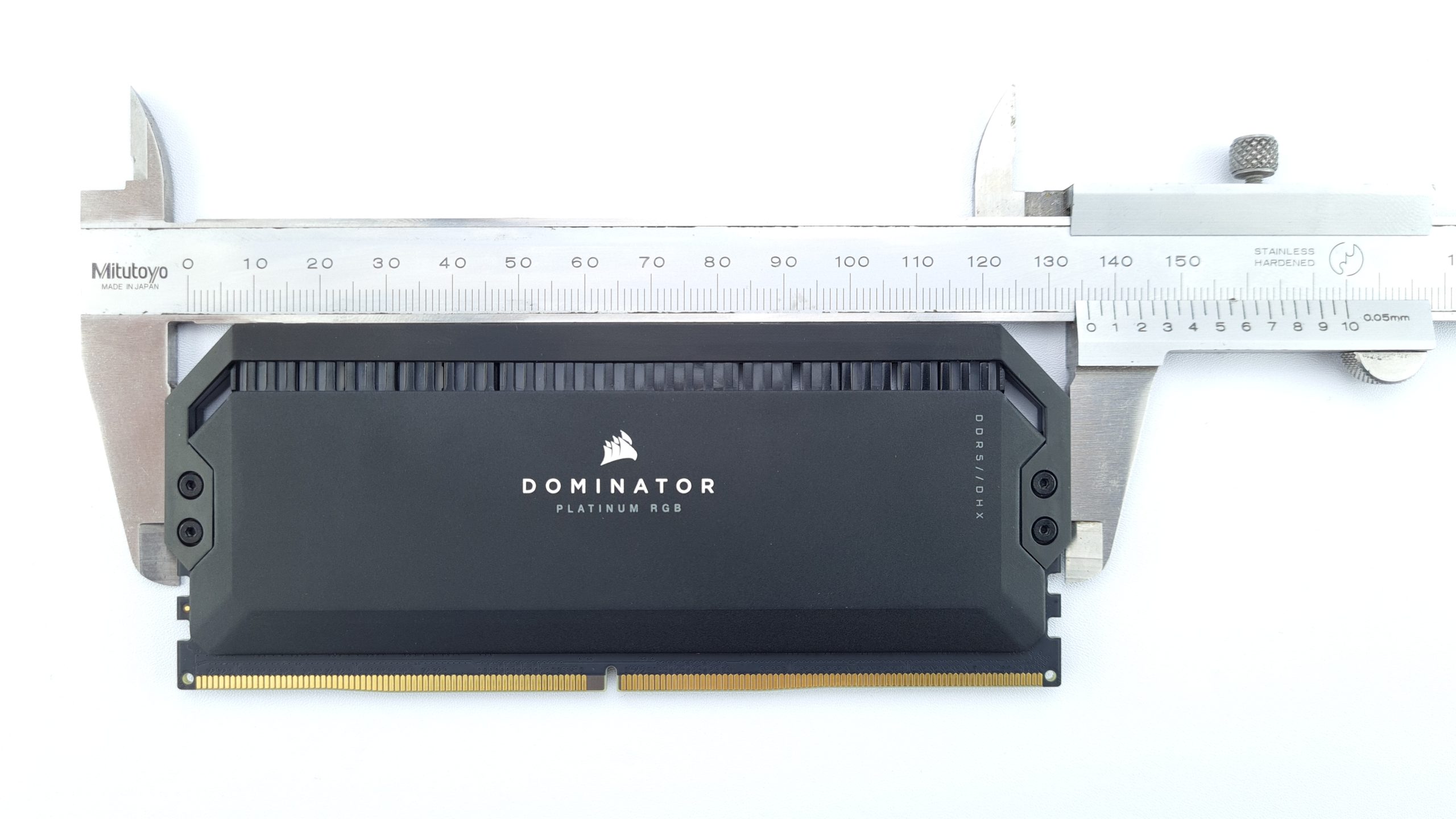
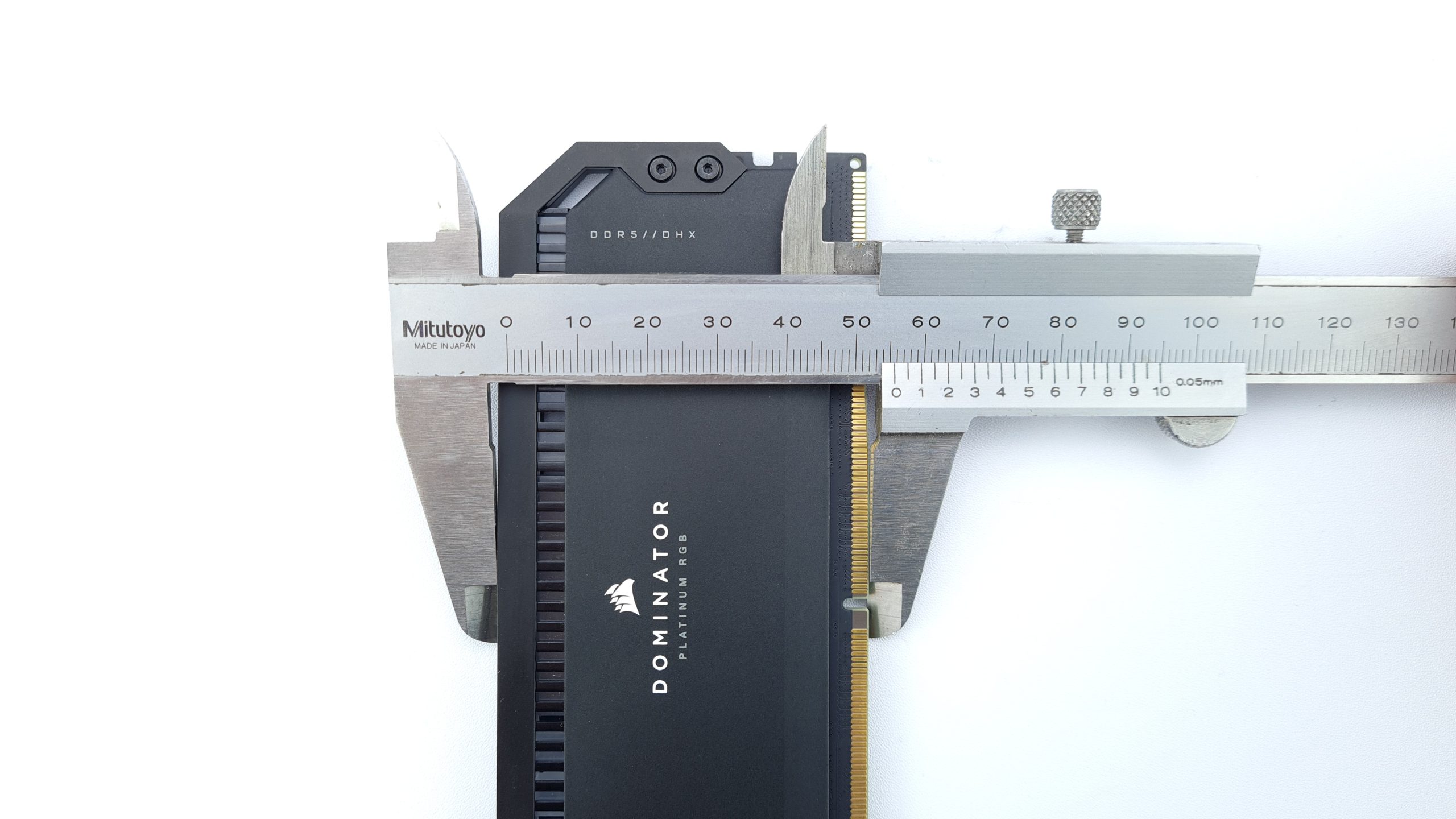
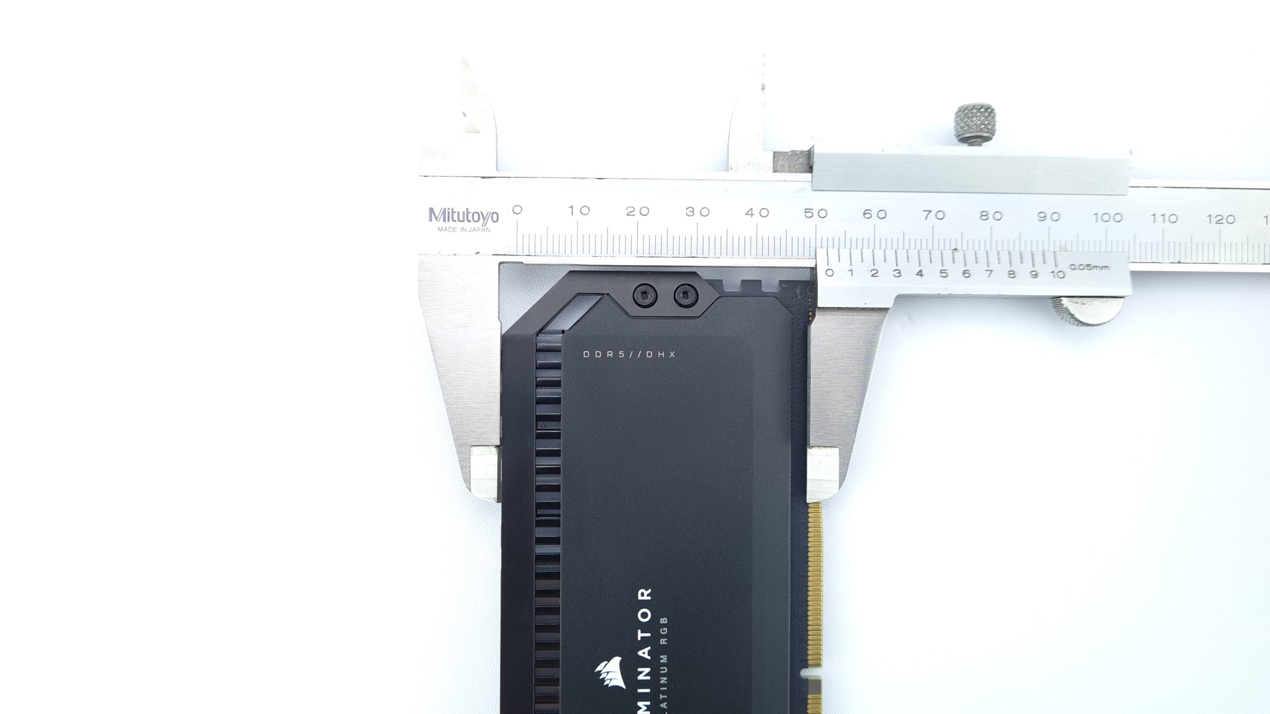
Since the heatsink with its attached frame protrudes a bit over the board at the sides, the total length is 136 mm, but the accessibility of the DIMM slot latches on the motherboard is not affected. The Corsair Dominator Platinum modules measure about 55 mm in height including the gold fingers, or 52 mm from the top edge of the DIMM slot when installed. So the modules are rather less compatible with air coolers that overhang the DIMM slots. On the other hand, you probably wouldn’t want to cover up your luminous RGB RAM modules anyway. Regarding weight, each module with their plentiful cooler shows 85 g on the scale.

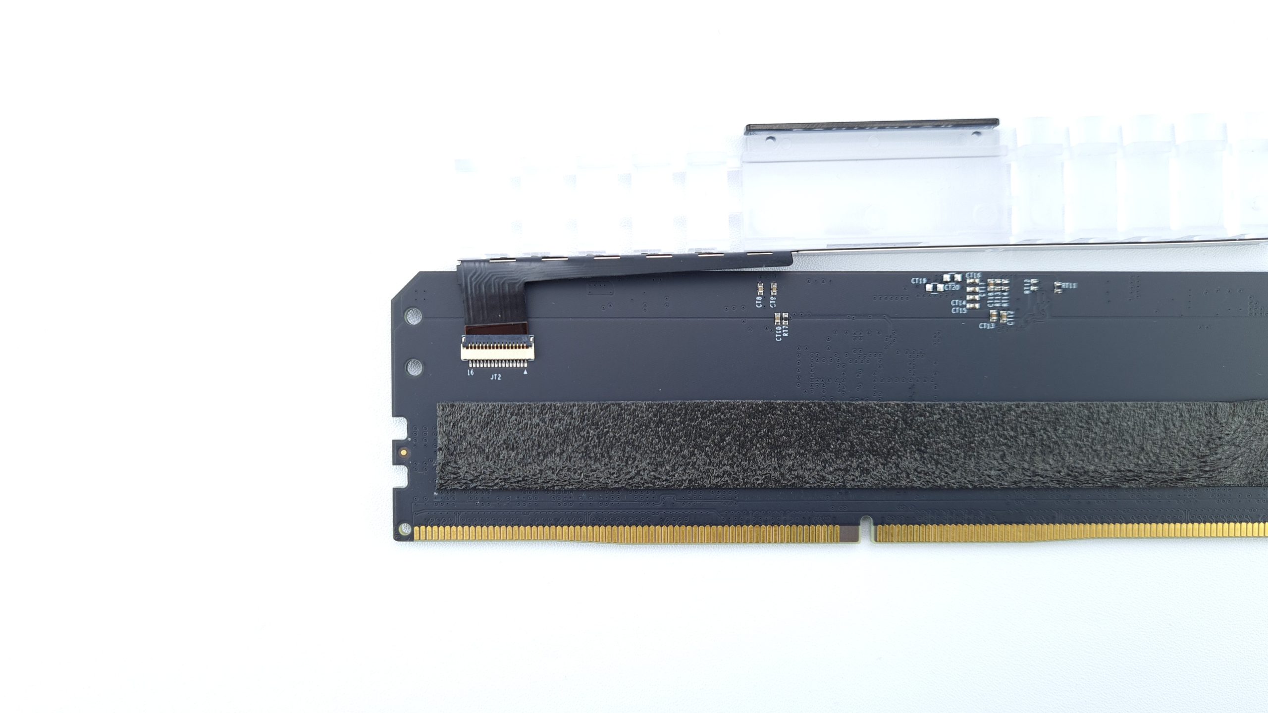
To dismantle the heatsink, simply remove the four 1.5 mm hexagon socket connecting screws from the frame. It is sufficient to press lightly on the back with a finger until the thread is completely loosened. Then the two halves of the cooler can be carefully levered off. The adhesive pads used are relatively easy to remove, but a short heating with a hairdryer is still recommended to avoid adhesive residues. The RGB light element above the PCB remains attached for now, as this can only be separated from the PCB after the cooler halves.
To do this, a clamp must first be released on the pcb side without memory ICs before the flexible ribbon cable that supplies power to the RGB light unit can be removed. Connectors of this type, more familiar from notebooks or game consoles, are relatively sensitive and should therefore be handled with particular care.
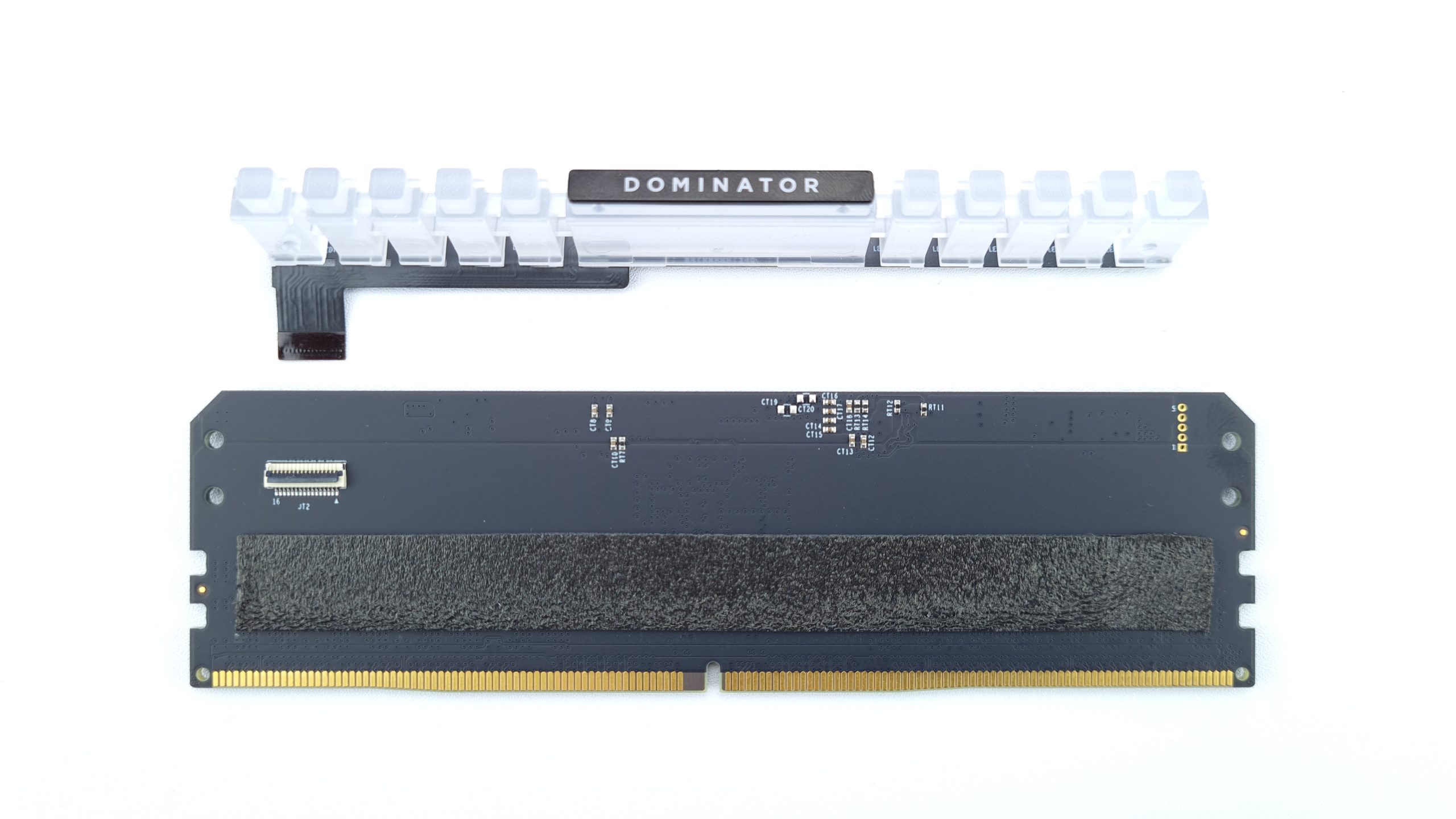
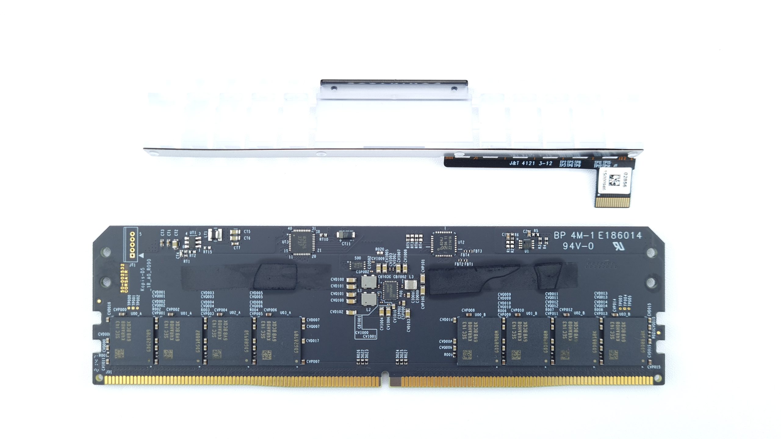
Now the actual RAM module is completely separated from its cooler and we can take a closer look at the construction. First of all, it is noticeable that the PMIC, i.e. the integrated voltage converter, itself is not directly cooled. Instead, Corsair uses about 40 mm wide thermal pads on both sides of the PMIC and above the memory IC’s to dissipate heat indirectly through the board to the heatsink. This should not be a problem for the PMIC itself, since these components can still be operated well above 100 °C, but this also indirectly heats the neighboring memory chips. After all, the thermal pads are installed on both sides of the module to make the best use of both halves of the heatsink.
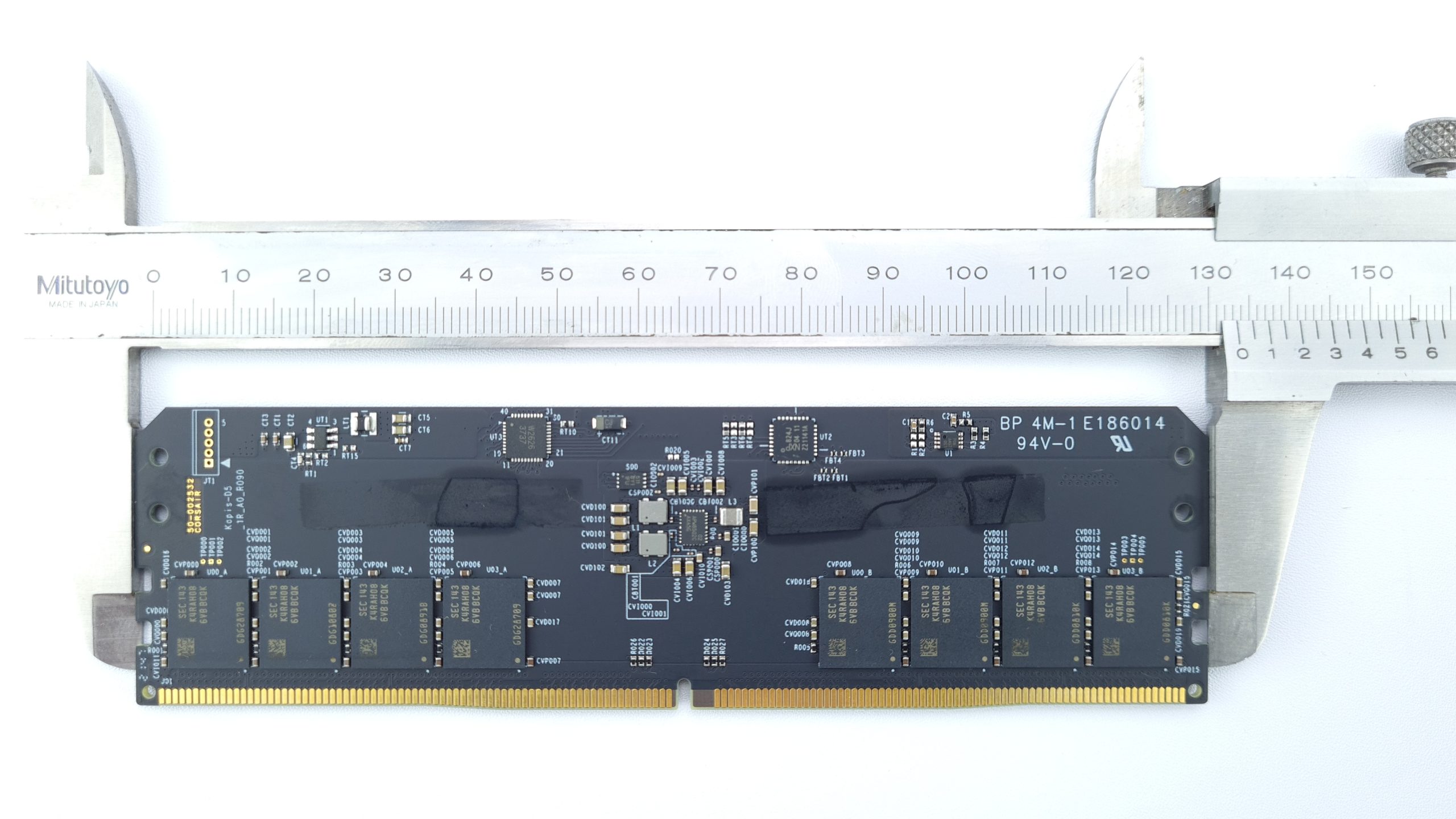
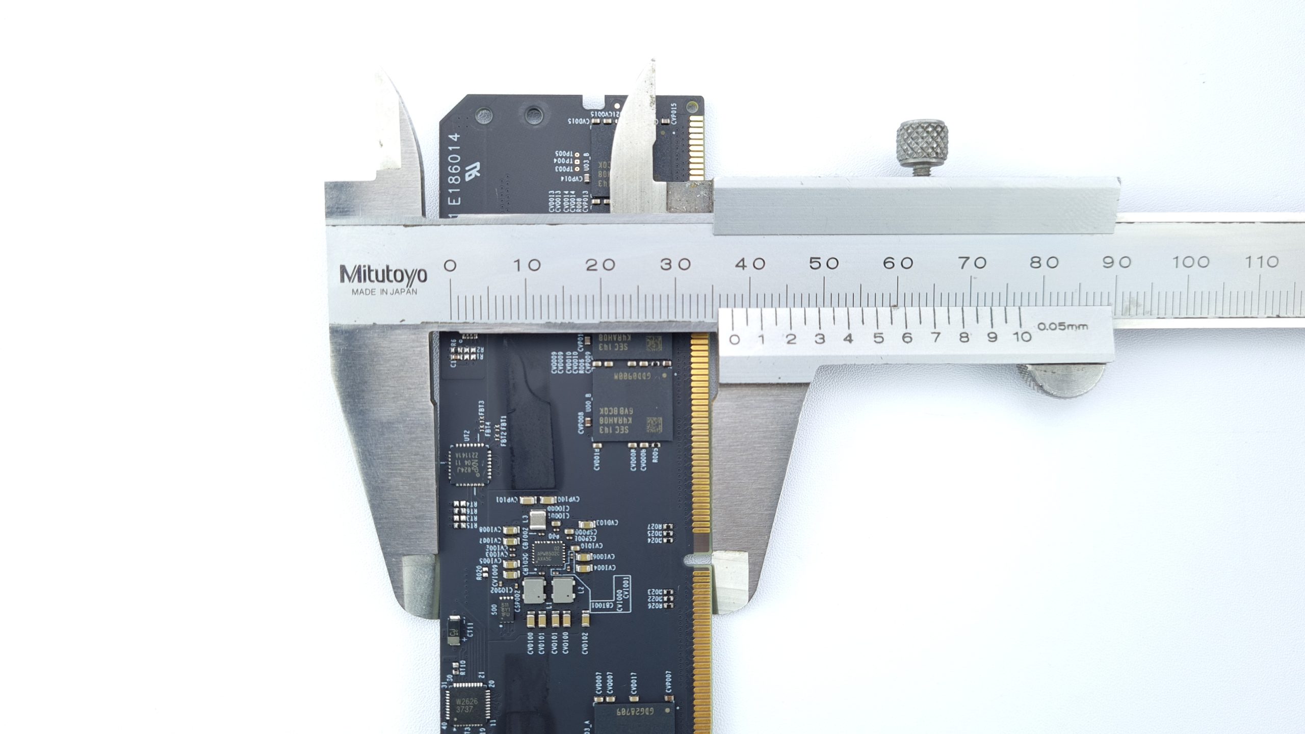
The board itself without heatsink now measures 133 mm in width, which is standard for DDR5, and about 37.5 mm in height, so about 34.5 mm from the upper edge of the DIMM slot. In cramped situations, this would save a little space if you were to provide the necessary cooling yourself. In addition, the modules look anything but ugly when completely exposed with their black circuit board, gold contacts and white labeling.

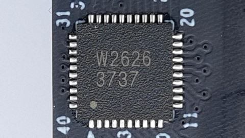
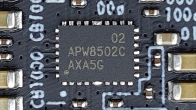
The RGB lighting is controlled by a NXP 824J controller together with a W2626 chip, which is probably responsible for the LED’s voltage supply. If you have any ideas on this, feel free to let me know in the forum thread. The PMIC integrated for the power supply is an ANPEC APW8502C, from which, among other things, the VDD, VDDQ and VPP voltages are generated.
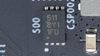
The SPD EEPROM chip, which holds the module information and also the XMP profile, is engraved 511 8Y1 1FU. Since we can read the temperature from the OS, it is at least certain that a temperature sensor must be integrated in the package.
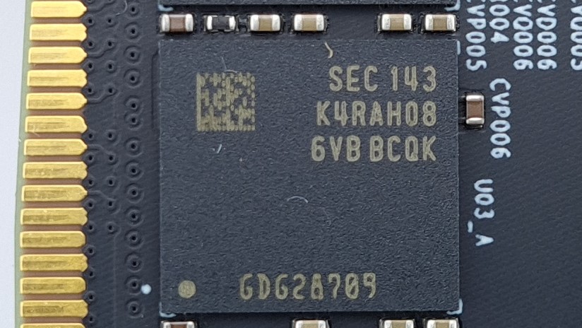
Now we come to the memory ICs, probably the most important component of a memory stick. Here Corsair uses Samsung 16 Gbit B-Die chips, recognizable by the engraving: SEC 143 K4RAH086VB-BCQK. Unfortunately there is no official documentation from Samsung on the nomenclature of DDR5 IC’s yet, but based on the DDR4 Product Guide I’ll go out on a limb and make the following assumptions:
- K: Samsung Memory
- 4: DRAM
- R: DRAM type – DDR5
- AH: Density – 16 Gbit
- 08: Bit Organization – x8
- 6: Number of benches – 32
- V: Interface – VDD, VDDQ 1.1 V
- B: Revision – 3. Generation, “B-The”
- B: Package type – FBGA
- C: Operating temperature – Commercial 85 °C
- QK: Binning – 4800 Mbps tCL 40, tRCD 40, tRAS 77
The current DDR4 Product Guide, from which I cribbed my assumptions, is available here: https://www.samsung.com/semiconductor/global.semi/file/resource/2018/06/DDR4_Product_guide_May.18.pdf

According to the markings, the PCB of the modules is manufactured by Brain Power (Qingyuan) Co.,Ltd from Taiwan with part number 4M1-E186014 and it is a 6 layer design.
- 1 - Introduction and unboxing
- 2 - Design and lighting
- 3 - Dimensions, teardown and PCB analysis
- 4 - SPD infos and heatsink performance
- 5 - Test systems and methodology
- 6 - XMP compatibility and overclocking
- 7 - Synthetic benchmarks – AIDA64, GB3, LinpackXtreme, SPI 32M
- 8 - Gaming 1440p – Cyberpunk 2077, SoTR, CSGO
- 9 - Gaming 1080p – Cyberpunk 2077, SoTR, CSGO
- 10 - Summary and conclusion


8 Antworten
Kommentar
Lade neue Kommentare
Urgestein
Mitglied
Urgestein
Urgestein
Veteran
Urgestein
Mitglied
Mitglied
Alle Kommentare lesen unter igor´sLAB Community →