


What should the ideal test setup look like?
Of course you can make it easy and use a benchtable. But in the end it’s free of any added value. What the customer needs are reliable statements, what happens to the motherboards in a closed case with built-in AiO compact water cooling and normal airflow including a quite potent and air-cooled graphics card if you let the CPU run freely up to 130 watts of power consumption? Then it’s about 400 watts of waste heat inside – in the worst case. And that’s exactly what interests me most!
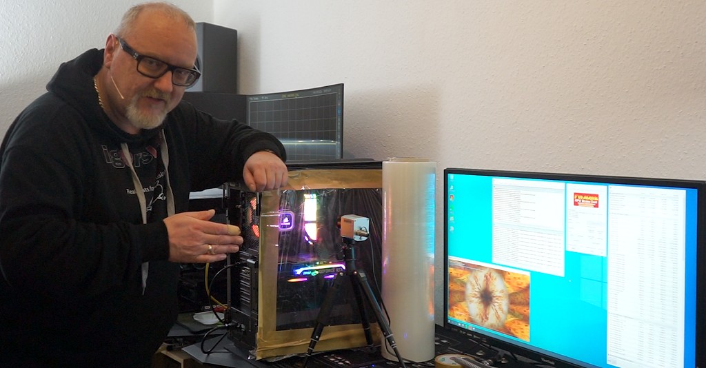
By the way, all three motherboards only allow about 90 watts to the CPU by default setting, no matter if Prime95 with AVX or not. So I measured twice, once with the 90 watts from the standard setting and once with 130 watts, which is also sufficient for Prime95 with AVX and up to 4.1 GHz Allcore. What distinguishes my test from many others is the special measurement in a closed case, which I would like to show you for the first time in the picture. The side walls on both sides are removed and the openings are glued airtight again with a special, wafer-thin foil. The transmittance of the foil is known and will be considered by me in the analysis software.
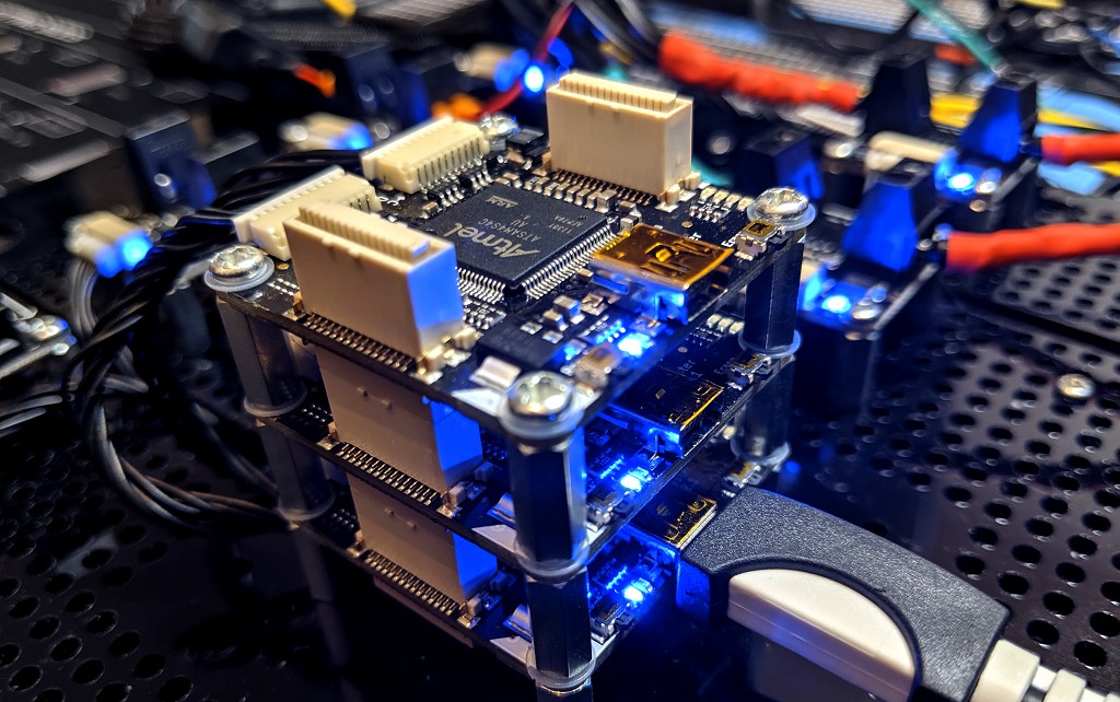
The maximum load of 90 or 130 watts for the CPU can be set very precisely by limiting the number of watts and the maximum currents in the motherboard and can of course be measured externally on the EPS. The monitoring is done via my new microcontroller-controlled measuring equipment for all rails between the power supply and the motherboard (test report will follow of course) as well as via HWInfo64, a software solution for the motherboard sensors.
The fan speed of the AiO was deliberately not designed for airflow, but as a silent setup in which the CPU stays in the green even after 30 minutes. This also applies to the rear fan, which also appears rather quiet with less than 1200 rpm. This of course increases the thermal load on the motherboard once again, but that’s the intention behind it to provoke the worst case at home. The room temperature is tester-friendly 22°C. I record all temperature changes as a radiometric video and can later read off the temperatures at any point. With the IR images one should also note that a real bolometer from Optris with 640 x 480 measuring pixels is used here and that the output graphics are not black/white VGA camera images with interpolated content from a tiny 80 x 60 pixel bolometer, as is the case with almost all handheld devices, but that they are real radiometric thermal images.
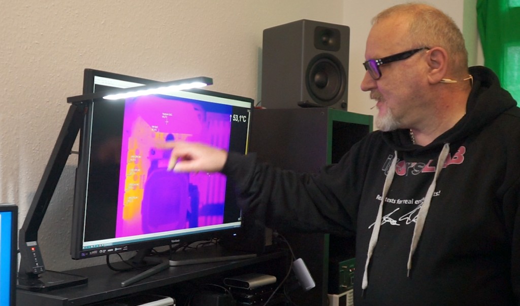
I test all motherboards consciously for a better clarity only with four (meaningful and representative) measuring points for the CPU and further for the SoC and other sources. The list shown on the IR images (#1 – #4) has nothing to do with the number of actually installed voltage transformer circuits, but refers to the relevant points and hotspots! The measurement is done from the front side, whereby I do not remove the coolers, but measure the free spots on the circuit boards next to the coils. The temperature difference between PCB and VRM is minimal, as I already found out with removed coolers. With VR coolers on, the temperatures in the MOSFETs are with a little luck even lower than on the coils with heated PCB! The second control measurement then records the matching areas on the back.
It is important that the VRM temperatures on all boards cannot be read out directly from the VRM by a sensor, but that the so-called Inductor DCR, i.e. a current measurement via the inductive resistance of the respective filter coils in the output area, is used again. Interestingly, the temperature of the MOSFETs can also be calculated approximately, even if only as an average value of all phases. This is important to know to be able to correctly classify the values from HWInfo64 and other tools that do not (can) represent hotspot values.
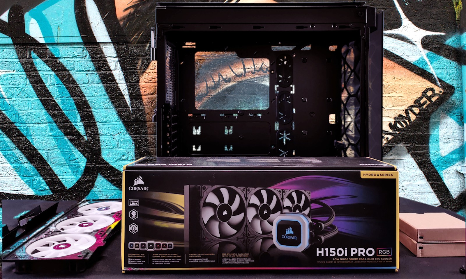
Corsair H150i Pro and the Ryzen 7 3700X
The H150i Pro RGB from Corsair does exactly what it’s supposed to do. At 2000 rpm, it’s not too lively to fall into your ears. The LL120 also does what you expect it to do. At the speeds of well below 1000 rpm used here, they are even quite mannerly and quietly. Well, and they can shine too. That doesn’t help with cooling, but it looks better. The cooling surface doesn’t match the hotspot of the Ryzen 7, so the cooling performance of a real CPU water block can’t be achieved.
But at least the 80 °C at 130 watts on the package can be seen after half an hour with such low fan speeds. Note: it’s also going much worse with other coolers. For higher wattage you would need a bit more wind from the fans. But the user wants it to be as quiet as possible, therefore I used this realistic setting.


Kommentieren