


The title already says everything we will find in the article today. Having recently presented in the article “Aqua Computer Flow Meter “High-Flow” in the laboratory test – What can a flow meter for 40 euros?”, two more sensors have to run today to determine a first winner. And since the “High Flow” is also available with USB connection and free software, I simply compared the already tested High Flow with two new candidates, who can even come up with a digital display and various read-out values. Then this comes back to some extent with the price. At least I thought.
But if you now think that I would first come up with the data sheets of the anonymously acquired test objects, all of which work with a paddle wheel according to the turbine principle, I have to disappoint. Because there is no real information about the measuring range, i.e. a lower and upper limit of the flow, including a tolerance limit. Yes, why not?
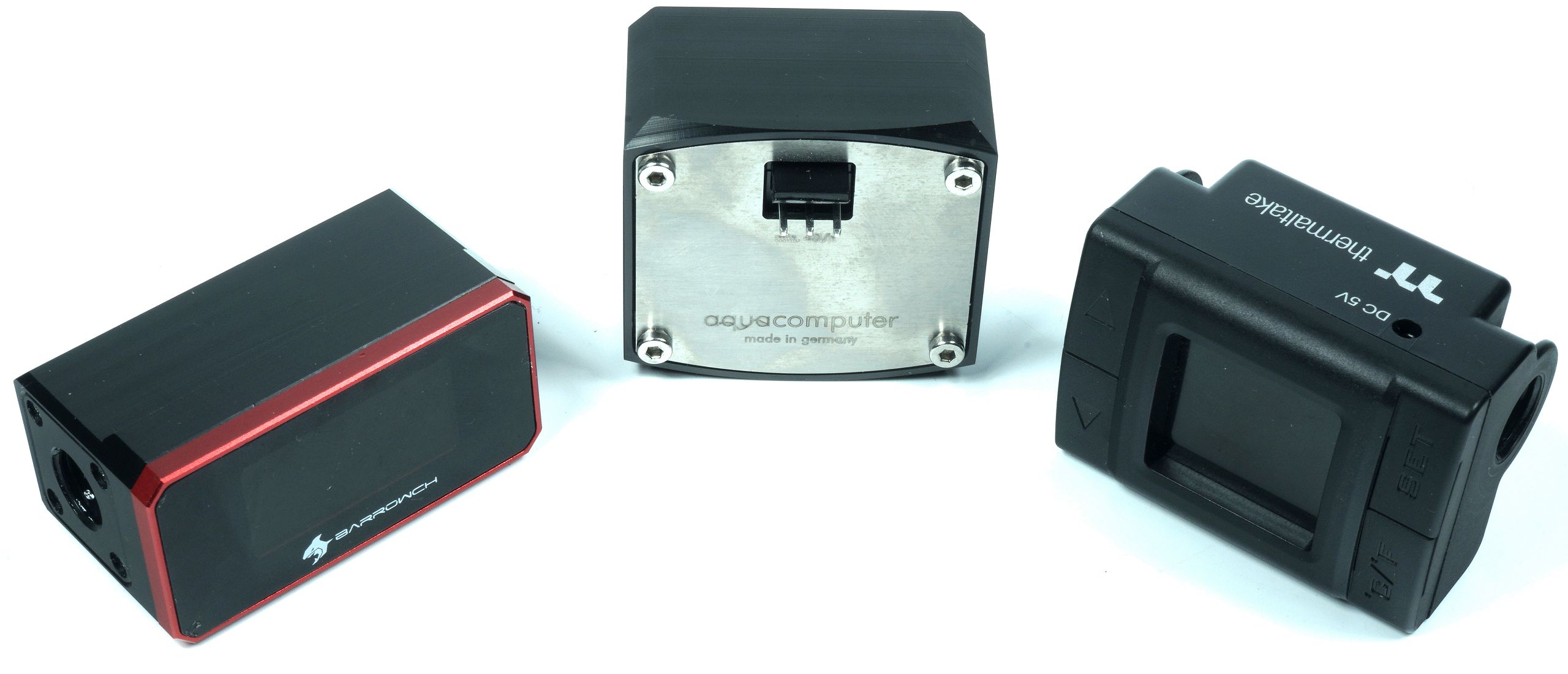
And there is no further information on the sensor technology used. The power supply connections are different. The sensor from Barrowch obtains the 12 volts via a 3-pin fan socket, the one from Thermaltaltake has a normal, round plug for 5 volts with adapter cable on SATA and the high flow as USB version obtains the 5 volts from the USB, the “normal” high flow shown here also hangs on 12 volts (pump or motherboard) or 12 volts. at the Aquaero.
The sensor from Thermaltake also measures the water temperature, which would also be true with the USB version and accessories on the high flow and if I can spoil something in advance: it is really the only valuable information that this display sensor offers. The Pacific TF1 still has a programmable monitoring function with beeps, which in the end annoyed me something that I would have preferred to have stepped on the sensor. With up to 150 liters per hour flow, of course, a very absurd idea.

So again: you get for approx. 50 Euro in the Asia shop of his choice (in Germany at the moment not even Amazon has such a thing at the moment) these various flow sensors with digital display. We already had that the Aqua Computer High Flow was a recommendation for its price. But today I really have to do something that I try to avoid strictly: to type a non-purchase recommendation into the CMS. And no, it’s not going to be a superficial crack, it’s going to be a real buying warning. Because if you really believe in what these parts indicate, you can immediately drain your water and turn back to air. That would at least be safer. But I’ll get to that in a while.
Test system and test conditions
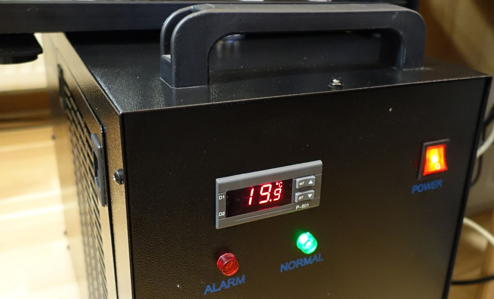
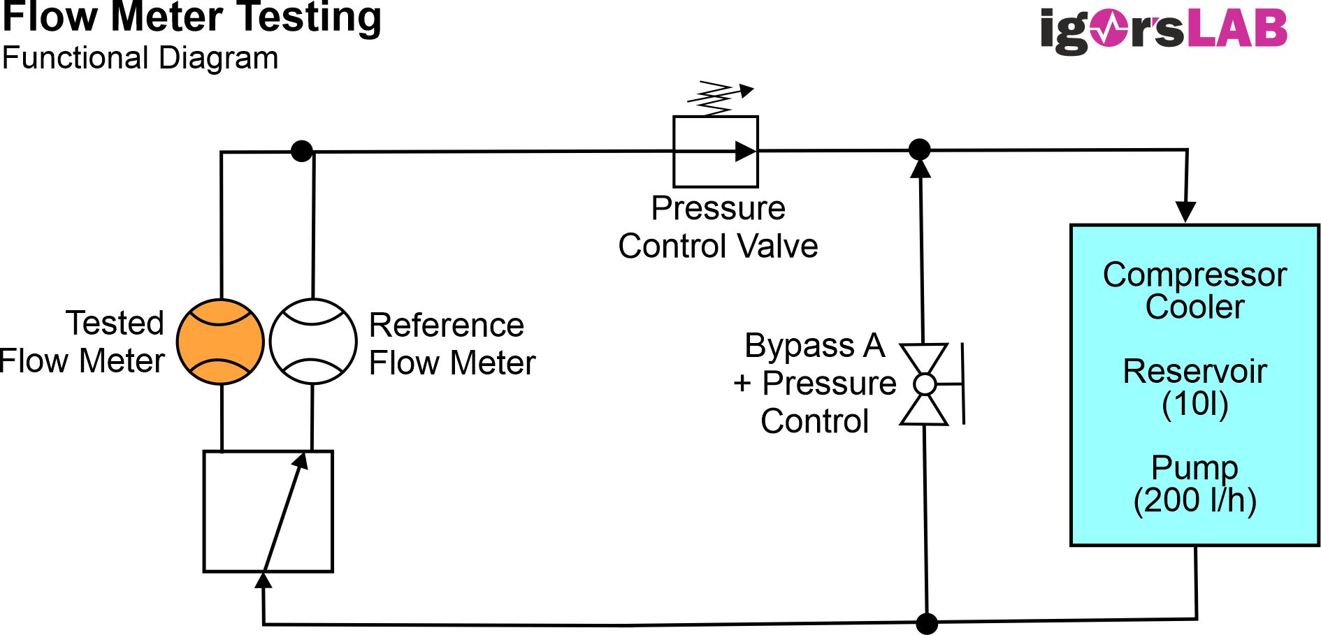
The core of the measuring setup is again a potent pump, which can deliver up to 200 l/h, a large compensating tank in the compressor cooler and an external one with a combined volume of almost 10 liters (here I have reduced the amount of water again somewhat), as well as the compressor cooler itself, whose hysteresis has been adjusted so that the temperature can be kept in advance up to 1000 watts of waste heat supplied between 19.5 and 20.5 °C. Smaller deviations are not feasible, however, the temperature can be measured in the lead-up and thus also a possible delta can be used to correct the collected measured values via a uniform time stamp. Clean distilled water is used, nothing more. Any suspended particles would only distort the measurement.
In order to avoid fluctuations in the volume flow (“flow rate”) in the area of the pump, I let them run unregulated at maximum power and redirect the volume flow with the help of bypass A instead. There, a fairly well dosed ball valve is used, which already helps to lower the volume flow in the large circuit through the “short circuit” via the bypass A. As a result, the volume flows are divided between the large and small circuit, so that the pump itself does not get a significant back pressure, which in turn could then push down the speed.
In order to be able to make an initial reference measurement here, the reference measuring device is first activated via the 2-way switch. With the fairly precise pressure control valve in the return of the large circuit, which relies on a large reduction by a screw thread, I can now adjust its volume flow relatively precisely and above all constantly and without large fluctuations. Even with larger volume flows around 3 l/m (i.e. 180 l/h), the measured fluctuation is only a maximum of 0.01 l/m.
If you are wondering why I did not position the valve in the lead-up, you can give a relatively simple answer. For the volume flow as such, the position in the circuit is rather unimportant, however, turbolenzen are created at the valve, which one wants to avoid as much as possible before an eneflow. In addition, the accumulation of air bubbles in front of the components to be tested can be almost completely excluded. By the way, the whole structure is flat and apart from the components, the hose is largely symmetrical.
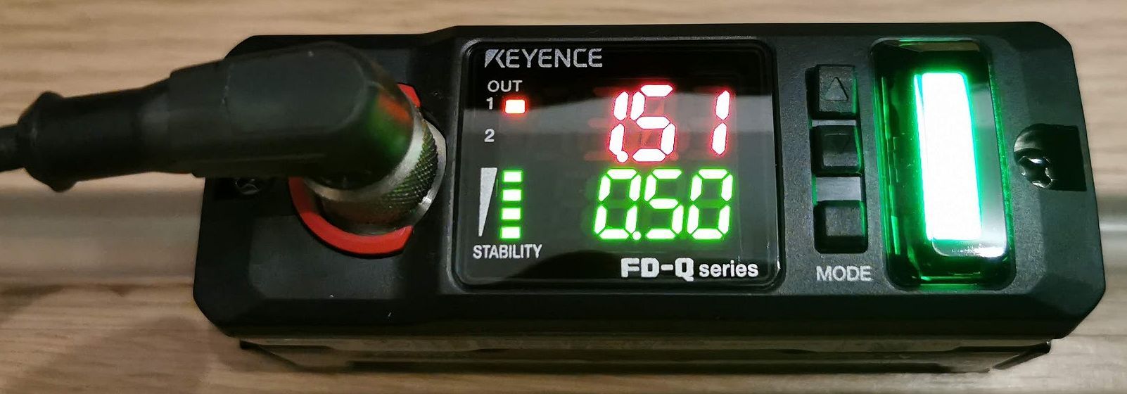
In order to determine the volume flow, I therefore rely on a well-defined measuring structure, which is not “picked apart” in the meantime. The centerpiece is a special, high-precision ultrasonic flow meter in the form of the Keyence FD-Q10C. This clampable flow meter works completely non-contact and does not affect the flow in the circuit. The accuracy far exceeds that of the mechanical solutions, so that here after calibration one gets a real reference value for the current volume flow.
The whole thing is fed via a special 4-pin M12 cable from an external power supply. In order to meet the pipe section used under the terminal exactly, I had the assembled components matched once again in a friendly laboratory in series connection to a calibrated device (M 1). The current volume flow is generally measured in litres per minute (l/m), not per hour. In addition to the limit value determination, the device also offers differential measurements and a freely definable zero point.
Equipped in this way, you can now also evaluate flow-sensures in the measuring circuit and always have the possibility to switch between this test object and the reeference sensor in real time for multiple valuations in order to detect a possible drift of the volume flow and, if necessary, to adjust something. The measurement results on the second page show how the whole thing can then be applied in practice and what can be gained from it in terms of knowledge.
[table id=4 /]


Kommentieren